manuals.online logo
Brands
  1. Home
  2. •
  3. Brands
  4. •
  5. PDK
  6. •
  7. Toy
  8. •
  9. PDK 42 Series User manual

PDK 42 Series User manual

42xx/72xx Instructions Raised running plate.
Note that these instructions cover the 72xx. Construction of the 42xx is identical apart from the
position of the rear body – chassis fixing point and the shorter bunker. The rear pony truck is
not in the 42xx.
Fig. 1.
Chassis Assembly
The chassis can be built rigid or compensated so decide now which one you are going to
make. If building a compensated chassis remove the sections from the axle holes.
Fold the main chassis frames (1) up and solder the rear frame spacer (2), centre spacer (3)
and front spacer/pony mount (4) in place making sure everything is square. Solder a 10BA
screw (8) into the hole in the pony truck mount and another into the hole in the rear stretcher
from underneath.
Compensated Chassis - Solder the axle
bearings (9) into the compensating beams
(7). Fit the compensating beams by passing
brass wire through the frames, through one
of the beams, then one of the springs, then
the next beam and finally out the other side
of the chassis. Hold the beams away from
the chassis side while soldering the wire in
place to prevent them being soldered to the
frames. Repeat for the second set of beams
and then trim the excess wire flush with the
chassis side. Fit the wheels so you can test
the compensating mechanism and when
satisfied that it works O.K. remove the wheels and put them to one side.
Rigid Chassis - Solder the axle bearings (9) into the axle holes in the chassis (1).
Take the cylinders (5) and curve the bottom of the cylinder sides to match the shape of the
cylinder front/rear. Fold down the front and rear and the sides and solder around the seams.
Fit the cylinders into the recess at the front of the frames.
Solder four lengths of the brass wire (10) into the holes in the chassis to form the brake
mountings. Take the brake hangers (11) and the brake blocks (12) and solder the blocks to the
hangers, making four L/H and four R/H. Solder the assembled brakes to the wire 2mm from
the frames. Pass more brass wire through the bottom of the brakes and then through the pull
rods (13). Solder all the joints. Refer to the inset drawing and assemble the brake actuating
rods and levers (14 & 15).
Solder the cylinder drain cocks (21) under the cylinders. Assemble the front pony truck (17 &
18) and the rear pony truck (22 & 23). Solder or glue the sandboxes (24) into their holes at the
rear of the chassis. Make up the sandpipes with brass wire and fit into the bottom of the
sandboxes. The chassis and pony trucks can now be painted, taking care not to gum up
moving parts.
Fit the wheels and motor to the chassis before fitting the slidebars. If you fit the slidebars first
you won’t be able to fit the front wheels!
Fold up the slidebars (19) as shown and solder the two sides together. Cut the end off of the
prongs that go into the cylinders. Solder together the three parts of the motion brackets (20)
and solder these into the notches on the slidebars. Now remove the stretcher at the rear of the
slidebars.
Coupling Rods and Valve Gear
With the chassis painted and the
wheels fitted permanently. Fit the
crank pins and assemble the
coupling rods (25) as shown.
Take care in this as the rods
need to move freely, both for side
play and compensation.
The connecting rods (26) can
also be assembled and
crossheads/slidebars attached to
the rods with the 16BA nuts and
screws. Check that the
crossheads move ok in the
slidebars before permanently fitting them.
Fig. 2.
Cut out the main running plate section (1), the valances (2 & 3) [leave the frames in place] and
the rear bufferbeam (6). Curve the front ends of the running plate round a 2mm bar. Solder the
rear bufferbeam into its recess in the running plate. Check the fit of the valances under the
running plate and then solder in place starting from the rear. Take the front running plate (4)
and fold down the front section. Form the front curve round a 3mm bar. Check this fits onto the
valances and then solder in place. Solder the front bufferbeam (5) in place. Solder two 8BA
screws (16) into the two holes in the running plate unit. Fold the splasher sides up.
Take the two main body sides (7 & 8), curve the front ends round a 2mm bar. Check that the
front curves match the curved mark on the running plate and tack them in place. Fit the cab
front (9) and rear (10) between the sides and tack in place. Tack the tank tops (13 & 14) into
the recesses in the sides. Once sure everything is square solder around all the seams. Shape
the bunker rear (11) to match the rear profile of the sides and solder in place. Fold down the
sides of the cab floor (12) and solder into the cab.
Curve the splasher tops (15) and solder to the splasher sides. Solder the smokebox saddle
front and rear (18) into their slots. Fold the saddle sides (17) to match the front, note that the
top section needs to be curved slightly. Solder these in place.
Before fitting the cab roof, move to figure 3.
Fig. 3.
Cut out the side overlays (23 & 24) carefully. Clean off all the tabs and curve the front end to
match the main sides. When a good fit is achieved cut out the support piece in the cab door
opening very carefully. Tack the overlays in position making sure they stay flat. When satisfied
that all is ok solder around the edges. Form the bunker rear overlay (27) and solder in place.
Use a fine file to put a radius on the edge where the sides and rear meet. Solder the rear door
(34) and rear window guards (35) in place.
Refer back to figure 2. [Fit the backhead (68) and reversing lever (69) before fitting the roof]
Curve the cab roof (19) and tack in position. When satisfied that it is positioned centrally solder
around the seams. Fit the front and rear strips (20), the two rainstrips (22) and the cab roof
shutter (21).
Solder the front and rear bufferbeam overlays (29) in place.
Check which type of motion bracket is required for your model and follow A or B below.
A. Punch through the rivets on the back of the large bracket overlay (31) and solder it to the
bracket back (30).
B. Solder together the two halves of the smaller bracket (32) and shape, and then solder the
bracket tops (33) around the edge.
Low melt solder will be needed for the whitemetal parts in the following section.
Now turn to the boiler (38). Solder along the bottom seam and then solder the smokebox
overlay (39) to the boiler. Take the firebox top casting (36) and the tapered boiler top (37) and
clean off any mould lines. Position the firebox top, tapered boiler and front boiler/smokebox to
check that they all line up correctly, make any alterations and line up again. Tack the firebox in
place, check the positioning again and then tack the tapered boiler section in place. Once
again check the position. Now tack the boiler/smokebox to the saddle and to the tapered
boiler. When you are happy all is lined up correctly solder all three firmly in place. Solder the
boiler band (44) around the boiler on the join between the parallel and tapered boiler sections.
Fold up the step on the smokebox front (40). Solder this to the smokebox.
Remove the valance frames and file the tabs off. Check the fit of the valance overlays (25 &
26) and solder in position.
Cut out the front running plate steps (41), cab steps and overlays (42) and bunker side steps
(43) and form the bottom steps on each one. Solder the cab step overlays to the steps. Fold up
the centre steps for the cab steps and the bunker steps and solder them in their slots. Now
solder all the steps in position.
Solder the rivet strips (44) around the bottom of the tanks and bunker.
Fit the buffer shanks (45) [leave the heads
until after painting].
Solder the bunker rear steps (46) into their
slots.
Solder the vac pipe (47) to the
bufferbeam.
Glue or solder the tank balance pipes (48)
behind the cab steps.
Drill two holes for the whistles (49) and glue them in place.
Fit the tank vents (50) into their holes.
Select either the tall safety valve bonnet
(51) or the short safety valve bonnet (52).
Make up the pipework from copper wire.
Solder the (53) chimney in place.
Glue the oil breathers (54) and tank fillers
(55) in place.
Drill the holes for the washout plugs (56)
and glue in place.
Solder the tank front steps (57) into their
slots.
Glue the superheater cover (58) to the
Smokebox.
Solder the motion bracket steps (59) into
the motion bracket.
Fit the lubricators (60) on top of the
splashers.
Glue or solder the steam pipes (61) in position. Drill a small hole and fit the lancecock (62).
Glue the bogie spring housing (63) into its hole. Glue the smokebox door handle (64) base
into the door and glue the handles to it. (The rear handle always points down).
Drill two holes in the smokebox for the front running plate support bars. Fashion the bars from
some thicker brass wire and glue in position.
Check photos for the position of the mudhole covers (65) on the firebox and fit these in
position.
Fit all the handrails and all the lamp brackets.
Chassis Parts List
1. Main Frames.
2. Rear Frame Spacer.
3. Centre Spacer.
4. Front Spacer/Pony Truck Mount.
5. Cylinders.
6. Cylinder End Covers.
7. Compensating Beams.
8. 10BA Screws & Nuts.
9. 1/8
th
Chassis Bearings.
10. Brass Wire.
11. Brake hangers.
12. Brake Blocks.
13. Brake Rodding.
14. Thicker Brass Wire.
15. Brake Actuating Lever.
16. 2mm Bearings (Pony Pivots).
17. Front Pony Truck.
18. Wheel Keeper & Guard irons.
19. Slidebars.
20. Motion Brackets.
21. Cylinder Drain Cocks.
22. Rear Pony Truck. (72xx only).
23. Wheel Keeper. (72xx only).
24. Sandboxes.
25. Coupling Rods.
26. Connecting Rods.
27. 16BA Nuts & Screws.
28. Springs.
Superstructure Parts List
1. Main Running Plate.
2. L/H Valance.
3. R/H Valance.
4. Front Running Plate.
5. Front Bufferbeam.
6. Rear Bufferbeam.
7. L/H Body Side.
8. R/H Body Side.
9. Cab Front.
10. Cab Rear.
11. Bunker Rear.
12. Cab Floor.
13. L/H Tank Top.
14. R/H Tank Top.
15. Splasher Tops.
16. 8BA Screws & Nuts.
17. Smokebox Saddle Sides.
18. Smokebox Front & Rear.
19. Cab Roof.
20. Front & Rear Detail Strips.
21. Cab Roof Shutter.
22. Rainstrips.
23. L/H Side Overlay.
24. R/H Side Overlay.
25. L/H Valance Overlay.
26. R/H Valance Overlay.
27. Bunker Rear Overlay.
28. Front Bufferbeam Overlay.
29. Rear Bufferbeam Overlay.
30. Large Motion Bracket Back.
31. Large Motion Bracket
Overlay.
32. Smaller Motion Bracket &
Overlay.
33. Bracket Tops.
34. Cab rear Door.
35. Rear Window Guards.
36. Firebox Top casting.
37. Boiler Top.
38. Smokebox/Boiler.
39. Smokebox Overlay.
40. Smokebox Front.
41. Front Running Plate Steps.
42. Cab Steps & Overlays.
43. Bunker Side Steps.
44. Rivet Strips.
45. Buffers.
46. Bunker Rear Steps.
47. Vacuum Pipes.
48. Tank Balance pipes.
49. Whistles.
50. Tank vents.
51. Tall Safety Valve Bonnet.
52. Short Safety Valve Bonnet.
53. Chimney.
54. Oil Breathers?
55. Tank Fillers.
56. Washout Plugs.
57. Tank Front Steps.
58. Superheater Cover.
59. Motion Bracket Steps.
60. Lubricators.
61. Steam pipes.
62. Lancecock.
63. Bogie Spring Housing.
64. Smokebox Door Handle.
65. Mudhole Covers.
66. Lamp Brackets.
67. Handrail Knobs.
68. Backhead.
69. Reversing Lever.
PDK MODELS. 8 RAME TERRACE. RAME CROSS. PENRYN, TR10 9DZ. CORNWALL.
Tel. 01209 861130
www.pdkmodels.co.uk - E-Mail: [email protected]

This manual suits for next models

1

Other PDK Toy manuals

PDK THE MORPETH LNER/BR D49/4 THOMPSON REBUILD User manual

PDK

PDK THE MORPETH LNER/BR D49/4 THOMPSON REBUILD User manual

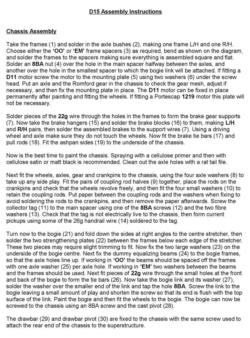
PDK D15 User manual

PDK

PDK D15 User manual

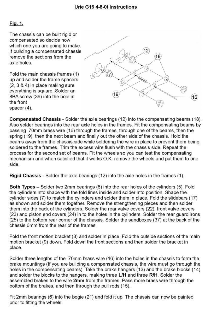
PDK Urie G16 4-8-0t User manual

PDK

PDK Urie G16 4-8-0t User manual

Popular Toy manuals by other brands

Fisher-Price Power Wheels N3089 owner's manual

Fisher-Price

Fisher-Price Power Wheels N3089 owner's manual

Fisher-Price GEO TRAX M2100 user manual

Fisher-Price

Fisher-Price GEO TRAX M2100 user manual

Fisher-Price COLOR PIXTER G6512 owner's manual

Fisher-Price

Fisher-Price COLOR PIXTER G6512 owner's manual

POLA G 333154 quick start guide

POLA G

POLA G 333154 quick start guide

Fisher-Price My First Dollhouse J0236 instruction sheet

Fisher-Price

Fisher-Price My First Dollhouse J0236 instruction sheet

Freewing REBEL FJ20311 user manual

Freewing

Freewing REBEL FJ20311 user manual

POLA G 330927 quick start guide

POLA G

POLA G 330927 quick start guide

Schmidt 51275 manual

Schmidt

Schmidt 51275 manual

Mattel Barbie X7945 instructions

Mattel

Mattel Barbie X7945 instructions

Educational Insights The Design & Drill Bolt-It Bucket manual

Educational Insights

Educational Insights The Design & Drill Bolt-It Bucket manual

Playskool Crawl n' Flutter Bee 06549 instruction manual

Playskool

Playskool Crawl n' Flutter Bee 06549 instruction manual

Roc Hobby swift operating manual

Roc Hobby

Roc Hobby swift operating manual

MTHTrains Proto-Sound 2.0 Digital Command System installation manual

MTHTrains

MTHTrains Proto-Sound 2.0 Digital Command System installation manual

Eduard DUKW with 105mm Howitzer quick start guide

Eduard

Eduard DUKW with 105mm Howitzer quick start guide

Fisher-Price Sit & Play manual

Fisher-Price

Fisher-Price Sit & Play manual

Fisher-Price L3479 instruction sheet

Fisher-Price

Fisher-Price L3479 instruction sheet

LEGO 75052 Star Wars Assembly guide

LEGO

LEGO 75052 Star Wars Assembly guide

Tamiya F-2 March 782 BMW instruction manual

Tamiya

Tamiya F-2 March 782 BMW instruction manual

manuals.online logo
manuals.online logoBrands
  • About & Mission
  • Contact us
  • Privacy Policy
  • Terms and Conditions

Copyright 2025 Manuals.Online. All Rights Reserved.