PDK Urie G16 4-8-0t User manual

Urie G16 4-8-0t Instructions
Fig. 1.
The chassis can be built rigid or
compensated so decide now
which one you are going to make.
If building a compensated chassis
remove the sections from the
axle holes.
Fold the main chassis frames (1)
up and solder the frame spacers
( , 3 & 4) in place making sure
everything is square. Solder an
8BA screw (36) into the hole in
the front
spacer (4).
Compensated Chassis - Solder the axle bearings (1 ) into the compensating beams (18).
Also solder bearings into the rear axle holes in the frames. Fit the compensating beams by
passing .70mm brass wire (16) through the frames, through one of the beams, then the
spring (19), then the next beam and finally out the other side of the chassis. Hold the
beams away from the chassis side while soldering the wire in place to prevent them being
soldered to the frames. Trim the excess wire flush with the chassis side. Repeat the
process for the second set of beams. Fit the wheels so you can test the compensating
mechanism and when satisfied that it works O.K. remove the wheels and put them to one
side.
Rigid Chassis - Solder the axle bearings (1 ) into the axle holes in the frames (1).
Both T pes – Solder two mm bearings (6) into the rear holes of the cylinders (5). Fold
the cylinders into shape with the fold lines inside and solder into position. Shape the
cylinder sides (7) to match the cylinders and solder them in place. Fold the slidebars (17)
as shown and solder them together. Remove the strengthening pieces and then solder
them into the back of the cylinders. Solder the rear valve covers ( ), front valve covers
( 3) and piston end covers ( 4) in to the holes in the cylinders. Solder the rear guard irons
( 5) to the bottom rear corner of the chassis. Solder the sandboxes (37) at the back of the
chassis 6mm from the rear of the frames.
Fold the front motion bracket (8) and solder in place. Fold the outside sections of the main
motion bracket (9) down. Fold down the front sections and then solder the bracket in
place.
Solder three lengths of the .70mm brass wire (16) into the holes in the chassis to form the
brake mountings (If you are building a compensated chassis, the wire must go through the
holes in the compensating beams). Take the brake hangers (13) and the brake blocks (14)
and solder the blocks to the hangers, making three L/H and three R/H. Solder the
assembled brakes to the wire 2mm from the frames. Pass more brass wire through the
bottom of the brakes, and then through the pull rods (15).
Fit mm bearings (6) into the bogie ( 1) and fold it up. The chassis can now be painted
prior to fitting the wheels.
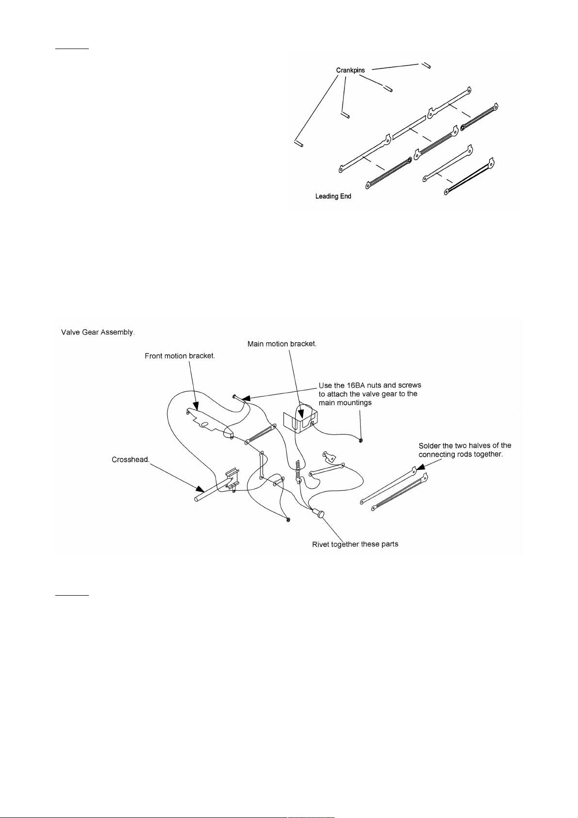
Fig. 2.
The driving wheels can now be fitted
permanently. (We recommend Markits
specific G16 wheels which include crank
pins). Assemble the coupling rods ( 6) as
shown in the diagram. Take care in this
operation as they must move freely for the
compensation to work. The connecting rods
( 7) can also be assembled.
Remove the crossheads ( 0) from their
sprues. Drill out the lower link on the
crossheads with 0.9mm drill. Check that the crossheads run freely in the slidebars and
adjust as necessary.
Fit the coupling rods to the wheels. Attach the connecting rods to the crossheads with the
14BA screws and nuts ( 8). Rivet together parts 9, 30, 31, 3 and 33. Note that there is a
specific order to work to. When this is done all the valve gear can be fitted to the relevant
brackets using the 16BA screws and nuts (35).
Fig. 3.
Cut out parts 1 to 9 from the fret. Remove all tabs. Take the running plate (1) and, using
the valances and their support frame ( & 3) as a template, form the running plate curves
and then fold the front section 90°. Line the valances up with the running plate and mark
the position of the kink in the valances. When a reasonable fit is obtained solder the
valance in place starting at the fold down points. Solder around the curves gradually
holding firmly in place as you go. This way the curves will be formed exactly with the
minimum of messing around. DO NOT remove the valance support frame yet!
Solder the rear buffer beam (4) into its recess, making sure that it is at 90° to the running
plate. Solder two 8BA screws into the holes in the running plate (Alternatively you can
solder 8BA nuts over the holes, if you prefer).

Solder the cab rear (5) into its slots (Fit the rear doors (38) now, or open the recess to
have the doors appear open). Take the cab sides (6 & 7) and the cab floor (8). Tack the
cab floor into the slots in the cab sides. Fit this unit into the slots for the cab sides. Make
sure it sits square and then solder in place and around all the seams. The cab front (9) can
now soldered into the slots in the floor.
Take the boiler (10) and solder the seam together. A piece of scrap brass soldered over the
seam on the inside will give added strength. Solder the smokebox front (11) onto the tabs
at the front of the boiler. Fit the inner smokebox wrapper [THICKER ONE] (1 ) around the
boiler and against the smokebox front. Do the same with the outer wrapper [THINNER
ONE] (13). Refer to the boilerband (79) dimension drawing and solder them in place now.
Use a small piece of tube/bar, roughly 15mm in diameter to curve the bands.
Check the fit of the boiler unit into the slots in the cab front and onto the tabs at the front of
the running plate. Check all sits square and when happy with the fit, tack it in place. Check
the alignment again and then solder in place permanently.
Take the front running plate (14) and form the curves. Use the front running plate valances
(16 & 17) as a guide. Solder the front buffer beam (15) into its recess, checking that it sits
square. Carefully form the kink in the valances, this needs to be done a bit at a time and
checked for fit as you go along. Solder them in place when you have a good fit. Offer up
the front running plate unit to the main running plate. The flat area between the curves
locates onto the tabs at the bottom of the smokebox front and the curves locate onto the
front of the main valances. Some fettling will be needed where the front and main valances
join together. When you have a good fit tack in place and check that it sits square, solder
around the seams when happy with the fit. Solder the front frames (18) in place against the
smokebox front and the running plate curves. Fit the bogie wheel arch sections (19) under
the running plate and in line with the front frames.
Fig. 4.
Take the tank sides ( 0 & 1) and fold the tank front in at 90°. The fold lines should be on
the inside. Shape the tank tops ( & 3) to match the angles of the tank sides. Fold the
tank ends down as shown on the drawing. Solder the tank tops into the recesses in the
tank sides and then solder the tank ends making sure the folds are all at 90°. Trim the
bottom of the tank ends level with the sides. Solder the tank inner sides ( 4) to the under
edge of the tank tops. Fit the assembled tanks into their slots and when happy with the fit
solder them in place. Make a solder join between the tank inners and the boiler for added
strength.
Take the bunker sides ( 5 & 6) and the bunker fronts ( 8). Fold the bunker fronts and form
the curve to match the recesses on the bunker sides. Trim as necessary and solder them
into the recesses. Fit them into their slots and solder in place. Take the bunker rear ( 7)
and, with the half etched lines facing inwards, shape the top to match the bunker sides.
Solder it in place.
Form the bottom edge of the riveted smokebox overlay ( 9) to match the smokebox front.
Solder it in place when you have a good fit. Solder the riveted smokebox front overlay (30)
in place, followed by the smokebox step (31). Solder the front and rear bufferbeam
overlays (3 & 33) in place.
Fit the cab backhead (78) into the cab using low melt solder. You can glue it if you prefer,
but solder is better.

Form the cab roof (34) to match the cab front and rear. Solder it in position so that there is
even overhang at the sides and the front and rear. Solder a piece of .7mm wire along the
side edges and then form the strengthening ribs (35 & 36). If using the later roof shutter
don't fit the rear of the two middle ribs (refer to fig. 5). if not, solder them all in place.
Solder the running plate curve steps (37) in place.
Fig. 5, 6, 7, 8 & 9.
Take the early roof shutter base (39) and the shutter top (40). Solder the base centrally to
the front roof section. Chamfer the edges of the shutter top and solder onto the base.
If using the later roof shutter, solder the base
(41) in position. Now fit the remaining rib,
cutting it to go either side of the shutter base.
Solder the shutter top (4 ) onto the base. You
can make it an open shutter if you want, by
cutting out the inside the shutter base.
Using .7mm wire, make up the cab handrails.
Solder the wire into the holes in the running
plate and then to the brackets on the tank and
bunker sides.
Solder or glue the following parts: washout plugs (43), Firebox valves (44), Safety valve
cover (45). Cut the bottom of the safety valves (81) off before fitting them.
Fold the lamp brackets (46) and solder them into the slots on the bunker
rear. Cut two pieces of the .9mm wire to represent the safety valves.
Fold up the rear steps (47). There are no slots provided as these were
fitted later on and may not be needed. Solder them in place using the
following measurements. Lower step 6mm up from running plate, upper
step 1 mm up from running plate. Lower step centre 9mm in from L/H
bunker edge and upper step centre 1 .5mm in from bunker edge.
Solder the buffers (48) into the bufferbeam. You may need to open out the holes
depending on which buffers are supplied. Repeat for the front.
Solder a vacuum pipe (49) onto the bufferbeam.
Fit the tank lifting eyes (50) into their slots.
Solder the tank inspection covers (51) in
place top 8mm from the fold in the tank
top.
Fold the oilbox brackets (5 ) using the
marks next to them on the fret as a guide.
Solder them in place mm from the tank
front.
Cut the oilboxes (53) off the sprue, angle the bottom of them and solder them in between
the legs of the bracket.

Two reversing bars are supplied, so that you can select forward
or reverse gear. Solder together the reversing bar (54 or 55) and
the reversing bar overlay (56).
Check that the spigot on the L/H reverser (57) passes through
the bottom of the reversing bar. Solder the reversing bar between
the tank and the boiler, you can get at it from inside the tank, and
the reverser to the running plate and the reversing bar. You may
prefer to glue the reverser in place. Fit the R/H reverser (58) in the same way.
Solder the dome (59) over the hole in the
boiler.
Solder the Chimney (60) over the hole in the
smokebox.
Fit the smokebox door (61) and the door
handle (6 ). The handle is in three pieces.
Solder a vacuum pipe (49) into the hole above
the bufferbeam.
Solder or glue the toolbox (63) between the
front frames.
Fix the clack valves (64) into the holes in the boiler and in the running plate, and then the
sandbox fillers (65) into their holes. Solder the outside steam pipes (66) to the running
plate. Fold the front lamp brackets and fit them in place.
Fold the cab steps (67) as shown and
solder under centrally under the cab
door opening. Solder the lower (68) and
top rungs (69) into the cab step. They
are marked underneath with a T & L as
they are different widths.
Fold the front running plate steps (70)
and solder them behind the bufferbeam.
Solder the middle rungs (71) into the
slots in the steps.
Solder the injectors (7 ) under the bunker,
about 1mm in from the valance and so that
the sandbox is seen in between the pipes.

G16 Details
Number 15in
Numerals
Unlined
Black
Later Cab
Ventilators
Plain
Stovepipes
BR
Number
BR
Livery
Snifting Valves
Removed
Withdrawn
49 09/1934 05/1938 05/1938 07/1941 1 /1948 0 /1953 1 /1947 01/1959
493 05/1939 05/1939 05/1939 05/1939 09/1948 09/1948 09/1948 1 /1959
494 09/1937 09/1937 0 /1941 0 /1941 09/1950 0 /1948 0 /1948 11/196
495 08/1936 08/1936 01/1938 01/1940 05/1948 11/1949 05/1948 1 /196
Chassis Parts List
1. Mainframes.
. Rear Spacer.
3. Middle Spacer.
4. Front Spacer.
5. Cylinders.
6. mm Bearings.
7. Cylinder Sides.
8. Front Motion Bracket.
9. Main Motion Bracket.
10. R/H Motion Bracket Overlay.
11. L/H Motion Bracket Overlay.
1 . 1/8th Bearings.
13. Brake Hangers.
14. Brake Blocks.
15. Pull Rods.
16. .7mm Wire.
17. Slidebars.
18. Compensating Beams.
19. Springs.
0. Crossheads.
1. Bogie.
. Rear Valve Covers.
3. Front Valve Covers.
4. Piston End Covers.
5. Rear Guard Irons.
6. Coupling Rods.
7. Connecting Rods.
8. 14BA Nuts & Screws.
9.
30.
31.
3 .
33.
34.
35. 16BA Nuts & Screws.
36. 8BA Nuts & Screws.
37. Sandboxes.

Bod Parts List
1. Main Running Plate.
. L/H Valance.
3. R/H Valance.
4. Rear Buffer Beam.
5. Cab Rear.
6. R/H Cab Side.
7. L/H Cab Side.
8. Cab Floor.
9. Cab Front.
10. Boiler.
11. Smokebox Front.
1 . Inner Smokebox Wrapper.
13. Outer Smokebox Wrapper.
14. Front Running Plate.
15. Front Buffer Beam.
16. L/H Front Valance.
17. R/H Front Valance.
18. Front Frames.
19. Bogie Wheel Arch Sections.
0. R/H Tank Side.
1. L/H Tank Side.
. R/H Tank Top/End.
3. L/H Tank Top/End.
4. Tank Inner Sides.
5. R/H Bunker Side.
6. L/H Bunker Side.
7. Bunker Rear.
8. Bunker Fronts.
9. Riveted Smokebox Overlay.
30. Riveted Smokebox Front.
31. Smokebox Step.
3 . Front Bufferbeam Overlay.
33. Rear Bufferbeam Overlay.
34. Cab Roof.
35. Middle Cab Ribs.
36. Outside Cab Ribs.
37. Running Plate Curve Steps.
38. Cab Rear Doors.
39. Early Roof Shutter Base.
40. Early Shutter Top.
41. Later Roof Shutter Base.
4 . Later Shutter Top.
43. Washout Plugs.
44. Firebox Valves.
45. Safety Valve Cover.
46. Lamp Brackets.
47. Bunker Rear Steps.
48. Buffers.
49. Vacuum Pipes.
50. Tank Lifting Eyes.
51. Tank Inspection covers.
5 . Oilbox Brackets.
53. Oilboxes.
54. Reversing Bar (Forward).
55. Reversing bar (Reverse).
56. Reversing Bar Overlay.
57. L/H Reverser.
58. R/H Reverser.
59. Dome.
60. Chimney.
61. Smokebox Door.
6 . Smokebox Door Handle.
63. Toolbox.
64. Clack Valves.
65. Sandbox Fillers.
66. Outside Steam Pipes.
67. Cab Steps.
68. Lower Cab Step Rungs.
69. Top Cab Step Rungs.
70. Front Running Plate Steps.
71. Middle Front Step Rungs.
7 . Injectors.
73. Medium Handrail Knobs.
74. Short Handrail Knobs.
75. Handrail Wire (.45mm).
76. .9mm Wire.
77. 8BA Screws & Nuts.
78. Cab Backhead.
79. Boilerbands.
80. Tank Fillers.
81. Safety Valves.
P.D.K. MODELS.
HILLTOP BUNGALOW.
CARNKIE
HELSTON
TR13 0DZ
07732213251
www.pdkmodels.co.uk
E-Mail: pdkmode [email protected]


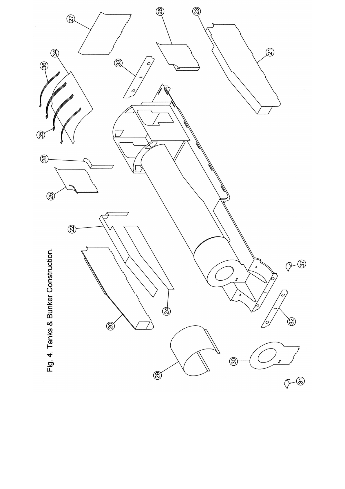

Table of contents
Other PDK Toy manuals


Popular Toy manuals by other brands


V-tech
V-tech Winnie the Pooh Press ‘n Play Learning... user manual

Circuit Cubes
Circuit Cubes Mechs Move! manual

Super Flying Model
Super Flying Model Sbach 342 Thunderblot instruction manual

marklin
marklin 39671 user manual

REVELL
REVELL Nieuport N.28 C-1 Assembly manual

Eduard
Eduard Tornado GR.4 quick start guide


