PDK THE MORPETH LNER/BR D49/4 THOMPSON REBUILD User manual

LNER/BR D49/4 THOMPSON REBUILD ‘THE MORPETH’ INSTRUCTIONS
CHASSIS ASSEMBLY
The chassis can be built rigid or compensated so decide now which one you are going to
make. If building a compensated chassis remove the sections from the front and rear axle
holes.
Take the frames (1) and solder the axle bearings (2) into the frames. old the chassis up and
solder the front and rear frame spacers (3) into their recesses. Solder the four 2mm bearings
(11) into the axle holes in the bogie (10). old the bogie sides down and solder the front and
rear spacers (12) into the slots.
COMPENSATION
Beam compensation requires a fixed
point, so that when the loco is on the
track it remains level. With this chassis
the fixed point is the bogie. Turn to the
compensating mechanism itself.
Solder the 1/8th axle bearings (2) into
the compensating beams (4). The
compensating spindle should be cut
from the brass wire (6). The beams
are held apart by the compensation
spring (5). It is very important that no
parts of this mechanism are soldered in a fixed position other than the spindle to the

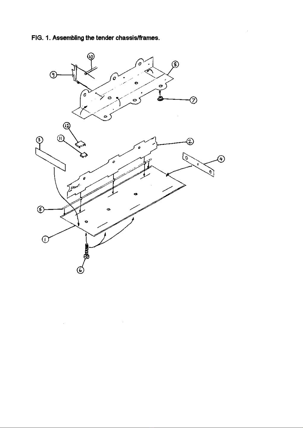
mainframe. Both beams must move independently of each other. The assembly of the beams
is otherwise very simple. Make sure you fit the beams so that the large hole is over the rear
brake pilot hole. it the wheels (to the bogie and chassis) so you can test the compensating
mechanism. it the bogie spacer (13) and then the bogie and when satisfied that all works
O.K. remove the wheels and the bogie and put them to one side.
BRAKE ASSEMBLY
Solder two lengths of the brass wire (6) into the holes in the chassis to form the brake
mountings (take care not to get solder on the compensation mechanism). Take the brake
hangers (8) and the brake block overlays (9) and solder the overlays onto the hangers. Solder
the assembled brakes to the wire 2mm from the frames. Pass more brass wire through the
bottom of the brakes and then through the brake rods (7) and solder the joints.
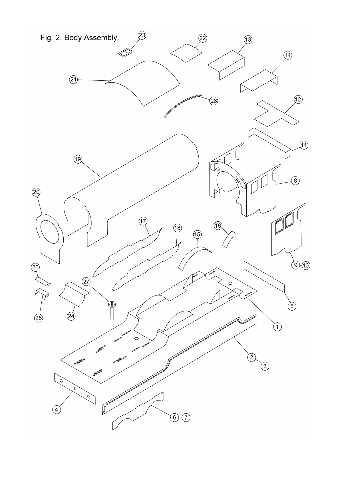
BODY ASSEMBLY
Take the running plate (1) and fit the valances (2 & 3) into the recesses under the running
plate. it the buffer beam (4) into the recess at the front of the running plate and the rear drag
beam (5) into the recess at the rear. it the lower front frame sections (6 & 7) under the
running plate. old the splashers up. Leave the valance supports in position until the boiler has
been fitted.
Take the cab etching (8) and fold the cab sides at 90° to the cab front. Check the fit of this into
the slots and when satisfied with the fit solder it in place. Curve the splasher tops (15 & 16)
and solder them onto the splasher sides.
Take the frame tops (17 or 18). Solder them into the slots in the running plate. Solder three
8BA screws (27) into the holes in the running plate.
orm the cab floor support (11) and fit between the cab sides, with a 1mm gap between it and
the rear of the running plate. Solder the cab floor (12) on top of the support. orm the interior
cab splashers (13 & 14) and solder them to the cab floor.
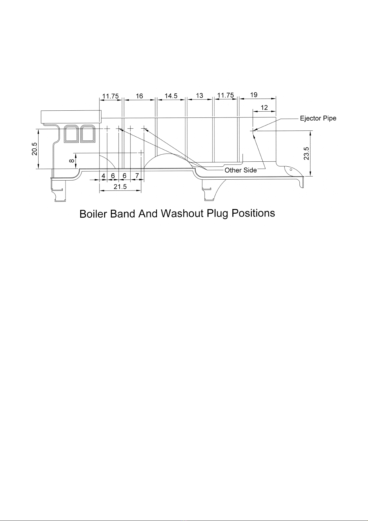
Now turn to the boiler (19). Solder the seam together. orm the bottom of the smokebox to
match the profile of the smokebox front. Solder the smokebox front (20) to the boiler, the tabs
on the boiler fit into the recesses on the smokebox front. it the boiler bands (28) now [see ig.
2a.]. Now check the fit of the boiler into the slots in the cab front. Tack it in place and when
satisfied that all is level solder both boiler and firebox firmly in place. Curve the cylinder cover
(24), check the fit between the frames and solder in place.
Solder the cab side overlays (9 & 10) in place. orm the cab roof (21) and tack it in place. The
front of the roof overhangs the cab front and the sides, when all is square solder around the
seams. Solder the rain strips (28) in place. Solder the roof vent (23) and the riveted plate (22)
in place.
Now remove the valance supports.
old the top of the cab steps (29) and running plate steps (30) over. old the bottom step up
as well and run some solder into the fold for strength. Solder them in place under the running
plate and against the valance. Solder the small steps into the slots.

Solder the chimney (31), dome (32) and anti
vacuum valve (33) in place.
Glue the smokebox door (34) into the
smokebox front
Drill out for the smokebox door handle (35)
and lamp brackets (36) and fit in place.
Solder the vacuum pipe (37) in place.
Solder together the two parts of the reversing
bar (38 & 39). orm the front end into an ‘S’
shape so that it fits behind the frames just in front of the splasher. Solder it in position when
happy with the shape.
Glue the whistle manifold cover (40) centrally at the
front of the cab.
The whistle (41) and safety valves (42) can be fitted
after painting.
Consult ig. 2a for the positions of the upper washout
plugs (43), lower washout plugs (44) and ejector pipe
hole.
Take the rocking grate rod cover (45), check the fit
onto the R/H front splasher and adjust as necessary.
The rod that protrudes from it will need to be replaced
with a piece of brass rod.
it the sandbox fillers (46) and the handrails behind
the fillers.
Glue the mechanical lubricator (47) in place. Solder the buffer shanks (48) in place. it the
handrails to the boiler and cab sides.

ig. 2a. Boiler Band Positions.


LNER 4200 GALLON GROUP STANDARD TENDER
This tender kit will make either the ‘Low f ont’ type built 1928 - 37 or the ‘High f ont’ type
built 1937 - 52. The low front type is suitable for B17’s, D49 (Hunts), O2’s and V2’s. The high
front type is suitable for V2’s and A2/1’s. ‘The Mo peth’ ran with the low front type.
As you are doing the ‘Low front’ type, follow igs 1, 2, 3 & 4. Ignore any reference to the ‘High
front’ type.
Fig .1.
Cut out the parts shown (1 to 8 inclusive) and file off all the tabs. Solder the frames (2) [only
one shown) into the slots in the base plate (1), (The larger oval cut out goes to the front). With
these in place solder the drag beam (3) and the buffer beam (4) against the appropriate end of
the frames. Solder the valences (5) into the recessed line approx 0.5mm in from the edge of
the base plate. Solder the three 8BA screws into the holes down the middle of the base plate.
it the frame side steps (11 & 12).
Open out the holes in the wheel carrier (8) to take the 2mm inside bearings (7) and solder all
six in place. old the sides and ends up at 90° (with the fold lines inside) to form a box section.
Solder around the seams.
Solder three lengths (25mm approx) of brass wire through the holes in the sides of the carrier.
Attach the brake hangers and blocks (9) (detail side facing out) to the wire about 2mm from
the sides, Pass brass wire through the bottom hole in the brakes and then through the two
brake rods (10) and then through the opposite brakes. Solder the wire to the brakes and then
solder the rodding in line with the frames. Paint the wheel carrier before fitting the wheels.
Fig.2.
Solder the coal plate support (13) into its slot. Solder the tender rear (14) into the rear slots
with the step holes on the L/H side looking from the back. Make sure the lamp bracket holes
remain clear,
Remove the front top section on the tender sides (15). Note that you have to drill one of the top
handrail holes to suit your period now (see diagram). Solder the sides in place. They butt up to
the tender rear.
With the fold lines on the inside fold down the front of the coal plate (16), old the coal space
(17) into the shape shown and solder it under the coal plate. Solder this unit into the second
set of slots at the front and all around the edges.
it the front bulkhead (18) with the fire iron cut out on the right. it either the early rear
bulkhead (19) for LNER/ea ly BR or the later rear bulkhead (20) for late BR. it the side
strengthening plates (21) and the rear plate (22) level with the top edges of the sides and rear.
The beading is included on these. Note that not all tenders had these plates, so if doing a plain
sided tender the beading will have to be fabricated out of wire,
Solder together the front ‘V’ bulkhead (23) and the infill piece (24). it this ‘V’ bulkhead into the
first set of slots. it the fire iron holders (25).

Fig. 3.
Solder either the closed coal door (27) or the open one (28) into place. Glue the two toolboxes
(26) in place on the front of the coal plate. Glue the brake and water standards (29) on either
side of the V bulkhead.
Solder the rear steps (30), the lamp brackets (31) and the vacuum pipe (32) in place. Glue the
two halves of the water dome (33) either side of the rear bulkhead. Glue the vacuum tank (34)
into the two holes to the left of the filler hole. ashion some suitable scrap fret into loops to
make up the tank securing straps. These will locate into the slots either side of the tank. it the
water filler (35) and the buffer shanks (36). Do not fit the buffer heads until after painting.
Fig. 4.
Solder the coal plate support (13) into its slot. Solder the tender rear (14) into its slots with the
step holes on the L/H side looking from the back. Make sure the lamp bracket holes at the
bottom remain clear.
Take the sides (15) (the front curve section ~ in place. Drill out the top handrail holes only on
this tender. Solder the sides into their slots. They butt up to the tender rear.
With the fold lines inside fold the front bulkhead (39) into the shape shown. Tack this into place
in the second set of slots. Check the fit of the coal plate (38) in the slots in the bulkhead. When
the bulkhead is positioned correctly, remove the coal plate and solder around the seams.
Cut the front square sections out of the coal space (17) and fold it as shown. Solder it under
the coal plate so that the front part will protrude under the bulkhead. Solder this unit in place.
it either the early rear bulkhead (19) for LNER/ea ly BR or the later rear bulkhead (20) for
late BR.
it the side strengthening plates (40) and the rear plate (22) level with the top edges of the
sides and rear, Note that all these tenders appear to have these plates. Solder together the
front ‘V’ bulkhead (41) and the infill piece (24). it this bulkhead into first set of slots.
Solder in place either the grills (43 & 45) or the doors (44 & 46). The doors were fitted after
November 1940. Solder in place the front bulkhead supports (48) and the two locker doors
(47). The brake and water standards (29) can now be glued in place.


CHASSIS PARTS LIST
1. rames.
2. Axle Bearings.
3. rame Spacers.
4. Compensating Beams.
5. Compensation Spring.
6. Brass Wire.
7. Brake Rods.
8. Brake Hangers.
9. Brake Blocks.
10. Bogie.
11. 2mm Bearings.
12. Bogie Spacers.
13. Bogie Pivot.
BODY PARTS LIST
1. Running plate.
2. R/H Valance.
3. L/H Valance.
4. Buffer Beam.
5. Drag Beam.
6. R/H Lower ront rames.
7. L/H Lower ront rames.
8. Cab ront/Sides.
9. R/H Cabside Overlay.
10. L/H Cabside Overlay.
11. Cab loor Support.
12. Cab loor.
13. R/H Cab Splasher.
14. L/H Cab Splasher.
15. ront Splasher Tops.
16. Rear Splasher Tops.
17. R/H Upper rames.
18. L/H Upper rames.
19. Boiler.
20. Smokebox ront.
21. Cab Roof.
22. Cab Roof Riveted Plate.
23. Cab Roof Vent.
24. Cylinder Cover.
25. ront Step Lower Section.
26. ront Step Upper Section.
27. 8BA Screws & Nuts.
28. Rain Strips.
29. Cab Steps.
30. Running Plate Steps.
31. Chimney.
32. Dome.
33. Anti Vacuum Valve.
34. Smokebox Door.
35. Smokebox Door Handle.
36. Lamp Brackets.
37. Vacuum Pipe.
38. Reversing Bar.
39. Reversing Bar Overlay.
40. Whistle Manifold cover.
41. Whistle.
42. Safety Valves.
43. Upper washout Plugs.
44. Lower washout Plugs.
45. Rocking Grate Rod Cover.
46. Sandbox illers.
47. Mechanical Lubricator.
48. Buffers.
49. Regulator Handle.
50. Backhead.
51. Brass Wire.
52. Handrail Knobs.
53. Ejector Pipe (form from thicker wire).
54. Split Pins.
55. Boiler Bands.
56. Brass Rod.
57. .
58. .
59. .

TENDER PARTS LIST
1. Baseplate.
2. Mainframes.
3. Dragbeam.
4. Bufferbeam.
5. Valences.
6. 8BA nuts and screws.
7. 2mm bearings.
8. Wheel carrier.
9. Brakes.
10. Brake rodding.
11. Small side step.
12. Large side step.
13. Coal plate support.
14. Tender rear.
15. Tender sides.
16. Coal plate (low front).
17. Coal space.
18. ront bulkhead.
19. Early rear bulkhead.
20. Later rear bulkhead.
21. Side strengthening plates (low front).
22. Rear strengthening plate.
23. V bulkhead (low front).
24. Infill piece (low front).
25. ire iron holders.
26. Toolboxes.
27. Coal door (closed).
28. Coal door (open).
29. Brake and water standards.
30. Rear steps.
31. Lamp brackets.
32. Vacuum pipe.
33. Water dome (two parts).
34. Vacuum tank.
35. Water filler.
36. Sprung buffers.
37. Handrail knobs.
38. Coal plate (high front).
39. ront bulkhead (high front).
40. Side strengthening plates (high front).
41. V bulkhead (high front).
42. Infill piece (high front).
43. Upper door.
44. Upper grill.
45. Lower grill.
46. Lower door.
47. Locker doors.
48. ront bulkhead supports.
49. Brass wire.
PDK MODELS.
HILLTOP BUNGALOW.
CARNKIE
HELSTON
TR13 0DZ
07732213251
www.pdkmodels.co.uk

Table of contents
Other PDK Toy manuals
Popular Toy manuals by other brands

B
B Build-a-ma-Jigs Submaplane BX1220 quick start guide

Zmodell
Zmodell ZDL-AZL-RS user manual

Learning Resources
Learning Resources LER 2442 Guide

Composite-ARF
Composite-ARF IMPACT F3A-type instruction manual

Phoenix Model
Phoenix Model KATANA-61 instruction manual

Carrera RC
Carrera RC Thunder Storm II Assembly and operating instructions