Peaco Support PEACO-FT-1KW User manual

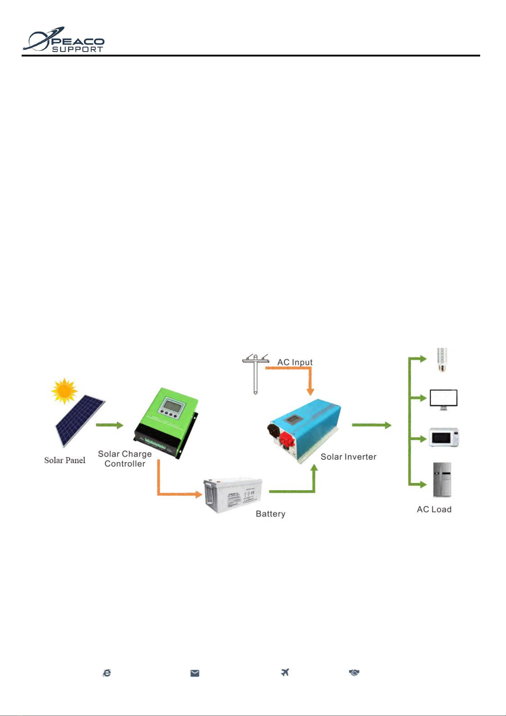
Off Grid Solar Inverter User Manual
- 2 -
www.peacosupport.com
sales@peacosupport.com
Global Shipping
Reliable Supplier
Dear Customers,
It's very grateful to you for trusting our company and selecting our products! Before using this product, please read carefully this user
manual, including installation, using, failure investigation and other important information and suggestion, we also suggest you keep this
manual well! For more solar inverters, please visit on peacosupport.com.
Note: Our company has the right of changing this user manual without any information.
Catalogue
1. Technology Parameter ------------------------------------------------------03
2. Product Features -------------------------------------------------------------03
3. Installation and Storage Instruction ---------------------------------------03
4. Inverter Appearance Diagram and Description--------------------------04
5. Operating Instructions ------------------------------------------------------05
6. Inverter Wiring Diagram----------------------------------------------------07
7. Maintenance -----------------------------------------------------------------09
8. Troubleshooting -------------------------------------------------------------09
Off Grid Solar Inverter User Manual
- 3 -
www.peacosupport.com
sales@peacosupport.com
Global Shipping
Reliable Supplier
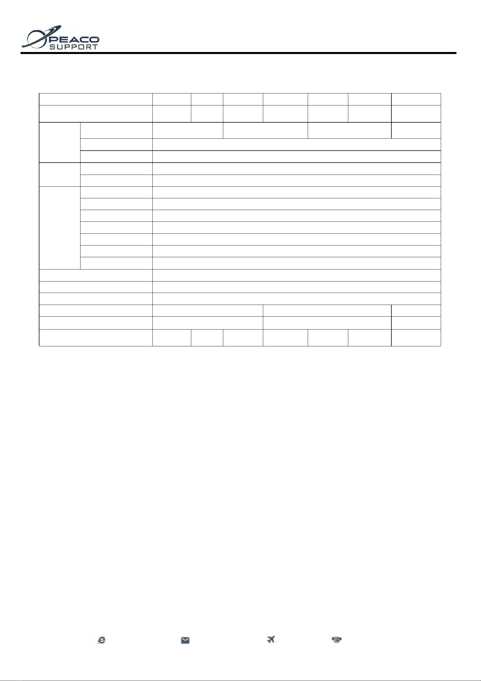
1. Technology Parameter
2. Product Features
Adopts dual CPU intelligent control technology, excellent performance.
The mains mode/battery mode can be set and the application is flexible.
The charging current/battery type can be set, which is convenient and practical.
Intelligent fan control, safe and reliable.
Pure sine wave AC output, can adapt to various types of loads.
The LCD displays the parameters of the inverter in real time and the operating status is clear to check.
Output overload, over voltage/low voltage, over temperature, short circuit protection, various automatic protections and alarms.
3. Installation and Storage Instruction
3.1 Unpacking Inspection
a. Open the package, inspect product accessories including 1 inverter and 1 piece user manual.
b. Inspect whether the inverter has been damaged during the transport or not, if it has some damage, don't start the machine, take the pictures and some video to
contact PEACO SUPPORT.
3.2 Precautions for Installation and Storage
3.2.1 The inverter installation should be operated by professionals.
3.2.2 When transporting the equipment, you need to take appropriate protective measures. When the equipment is moved from a low-temperature environment to
a high-temperature environment, water droplets may appear. Make it dry completely before use to ensure safety.
3.2.3 Do not expose the inverter in harsh environment such as humid, flammable, explosive or a large amount of dust environment. Do not cover or block the
vents and reserve an air circulation gap of more than 10cm around the inverter in order to have good heat dissipation.
3.2.4 When the device is not connected to the mains and it is not used for a long time, the battery switch must be turned off.
Model PEACO-FT-
1KW
2KW
3KW
4KW
5KW
6KW
8KW
Rated power
1000W
2000W
3000W
4000W
5000W
6000W
8000W
Battery
Rated voltage
12V DC/24V DC
/48V DC
12V DC/24V DC
/48V DC
24V DC/48V DC
/96V DC
48V DC
/96V DC
Charge current
30A(default)-C0-C6 can be set
Battery type
U0-U7 can be set
Input
Voltage range
85V-138VAC/170V-275V AC
Frequency
45Hz-65Hz
Output
Voltage range
110VAC/220VAC/230VA C, ±5%( Inverter mode)
Frequency
50/60Hz±1%( Inverter mode)
Output wave
Pure sine wave
Switching time
<10ms( typical load)
Efficiency
>85%(80% Resistance load)
Overload
110-120%/30S;>160%/300ms;
Protection
Battery over voltage/low voltage, overload, short circuit protection, over temperature protection, etc.
Operating ambient temperature
0-40℃
Storage ambient temperature
-15 - +50℃
Operating / Storage ambient
0-90% No condensation
Machine Size: L*W*H (mm)
486*247*179
555*307*189
653*332*260
Package size: L*W*H(mm)
550*310*230
640*370*240
715*365*310
N.W / G.W (kg)
11/13
14/16
16/18
23/27
26/30
30/34
55/59

Off Grid Solar Inverter User Manual
- 4 -
www.peacosupport.com
sales@peacosupport.com
Global Shipping
Reliable Supplier
4. Inverter Appearance Diagram and Description
4.1 Inverter Appearance View 4.2 1KW/2KW/3KW View of Inverter Appearance
4.3 4KW/5KW/6KW/8KW View of Inverter Appearance
4.4 Specification
①Fan. ②AC input/output terminal. ③AC input/output fuse holder. ④RS232 communication interface (optional function). ⑤Battery terminal negative
input terminal. ⑥Battery terminal positive terminal. ⑦Earth terminal.
5. Operating Instructions
5.1 Panel LCD Display Icon Description
5.1.1 LCD Display and Function Keys Interface
They can display the inverter working status, such as input / output voltage, frequency, grid mode, inverter mode, battery capacity, load capacity, alarm warning,
etc.
5.1.2 Keys Description
Function keys
Instruction
Mute / function key
Sound attenuation with short press, enter into equipment working mode with long press.
Function key / multiply key
Enter into charge current setting with long press 5s, increment with short press.
Function key / reducing key
Enter into battery mode setting with long press 5s, decrement with short press.
ON / OFF
Single bond ON / OFF control.

Off Grid Solar Inverter User Manual
- 5 -
www.peacosupport.com
sales@peacosupport.com
Global Shipping
Reliable Supplier
5.1.3 LCD Display Instruction
inverter parameter instruction
LCD
display
Function instruction
AC input voltage parameter
AC output frequency parameter
AC output voltage parameter
Equipment working mode selection
Grid priority mode
Battery priority mode
Battery icon instruction
LCD
display
Status
Battery voltage values/12V;*A
(pcs)
Twinkle
<10.5V;*A
Lighten
10.5~11.2V;*A
Lighten
11.2~11.6V;*A
Lighten
11.6~12.1V;*A
Lighten
12.1~12.5V;*A
Lighten
>12.5V;*A
Working mode icon instruction
LCD display
Function instruction
Grid input icon
AC-DC icon
DC-AC icon
Buzzing icon instruction
Lighten
Prohibit buzzer tweet
dark
Start buzzer tweet
Fault/abnormal icon instruction
Fault/Abnormal reminder
Load icon instruction
LCD
display
Function instruction
Output overload reminder
0%~25%
25%~50%
50%~75%
75%~100%

- 6 -
www.peacosupport.com
sales@peacosupport.com
Global Shipping
Reliable Supplier
DC Contactors
5.2 Panel key / LCD Setting Instruction
Function key
Operating Instructions
Mute key
Long press for 1 second, buzzing 1 time, start mute state. Long press for 1 second again, buzzing
2 times, close mute stage.
Function key
Long press for 5s, 01, 03 mode can be recurrent selection, it will take effect after restarting.
Grid priority mode
Battery priority mode
Function key
Long press for 5s,LCD panel will display relative charge current regulation C+, press
increase charge current,press decrease charge current.
C0
C1
C2
C3
C4
C5
C6
0A
5A
10A
15A
20A
25A
30A
Function key
Long press for 5s,LCD panel will display charge voltage regulation U+, press
increase charge voltage from U0 to U7,press decrease charge voltage from U7 to U0.
U0
Gel U.S.A
13.7V
U1
A.G.M.1
13.4V
U2
A.G.M.2
13.7V
U3
Sealed lead Acid
13.6V
U4
Gel European
13.8V
U5
Open lead acid
13.8V
U6
Calcuim(open)
13.6V
U7
De sulphation cycle 15.5 for 4 hrs
ON/ OFF key
Starting up
Long press for 2s, buzzing 1 time, equipment start output
Power off
Long press for 2s, Long press for 2, after internal relay energized, the equipment
power off output.
Function key
Long press for 5s, LCD panel will display relative charge current regulation C+, press
increase charge current,press decrease charge current.
C0
C1
C2
C3
C4
C5
C6
0A
5A
10A
15A
20A
25A
30A
Function key
Long press for 5s, LCD panel will display charge voltage regulation U+, press increase
charge voltage from U0 to U7,press decrease charge voltage from U7 to U0.
U0
Gel U.S.A
13.7V
U1
A.G.M.1
13.4V
U2
A.G.M.2
13.7V
U3
Sealed lead Acid
13.6V
U4
Gel European
13.8V
U5
Open lead acid
13.8V
U6
Calcuim(open)
13.6V
U7
De sulphation cycle 15.5 for 4 hrs.
ON / OFF key
Starting up
Long press for 2s, buzzing 1 time, equipment start output.
Power off
Long press for 2s, Long press for 2, after internal relay energized, the
equipment power off output.

- 7 -
www.peacosupport.com
sales@peacosupport.com
Global Shipping
Reliable Supplier
DC Contactors
5.3 Working Mode Instruction
Icon
Working Mode
Running State
Mains priority mode
In the mains priority mode, after the inverter is started, when the mains input is normal, the inverter
provides power to the load through the mains bypass voltage stabilization and at the same time
supplements the battery pack. When the mains are in the high/low/severe abnormal situations, the inverter
converts the energy of the battery pack into high-quality power through an internal module and provides
it to the load.
Battery priority mode
Battery priority mode operation. When the mains input is normal and the battery pack is full, the mains is
just waiting for standby. The inverter converts the battery energy into high-quality power through the
internal module and provides it to the load. When the battery power drops to the low voltage threshold,
the device automatically supplies power to the load through the mains bypass voltage stabilization, but it
does not charge the battery pack. This mode is mainly for the design of new energy power generation
systems (such as wind and solar power generation systems).
5.4 Sound Alarms Instruction
Equipment running normal
Buzzing prohibit
Buzzer is no tweet under default state.
Buzzer starts
Buzzer tweet 4 times every 15s, indicating the
inverter is operating under battery inverter state.
Battery high voltage alarm
Buzzer tweets 4 times per second, alarms high voltage.
Battery low voltage alarm
Buzzer tweets 2 times per second, alarms low voltage.
Over temperature alarm
Buzzer alarm 2 seconds pause 1 second.
5.5 Precautions for Generator Connection
If you connect the generator, you need to follow the steps below to run.
A. Start the generator and connect the output power of the generator to the input terminal of the equipment after its operation is stable. At this time, make sure that
the equipment output is in the no-load state and then turn on the inverter.
B. After the inverter is turned on, connect the loads one by one.
C. It is recommended to select the capacity of the generator with a capacity of 2-3 times the inverter power.
6. Equipment wiring diagram
6.1 12VDC Series Battery Wiring Diagram 6.2 24VDC Series Battery Wiring Diagram

- 8 -
www.peacosupport.com
sales@peacosupport.com
Global Shipping
Reliable Supplier
DC Contactors
6.3 48V DC Series Battery Wiring Diagram(It is 8 pieces of 12V DC battery connected in series of 96V DC series battery connection)
6.4 Input/output Connection Diagram
6.5 Direction for Using of Wire Diameter
Direction for using of battery, AC input / output wire diameter. (Calculation is based on 1mm2copper core with 4-5A current.)
For example: Wire diameter of 5000W/48V DC/220V AC as below.

- 9 -
www.peacosupport.com
sales@peacosupport.com
Global Shipping
Reliable Supplier
DC Contactors
7. Maintenance
7.1 This series of products requires very little maintenance and the battery only needs to be constantly charged to obtain the expected life.
7.2 f you do not use the inverter for a long time, it is recommended to charge it every 4-6 months. Under normal circumstances, the service life of the battery is 3-
5 years. If it is found to be in poor condition, it must be replaced early. When replacing the battery, it must be performed by professionals. The battery should not
be replaced individually and the battery instructions should be followed when replacing the battery as a whole.
7.3 Before replacing the battery, turn off the inverter, disconnect from the mains and turn off the battery switch. Take off metal objects such as rings and watches.
7.4 When connecting the battery cable, a small spark at the joint is normal and will not cause harm to personal safety and equipment. Never short-circuit or
reverse-connect the positive and negative electrodes of the battery.
8. Troubleshooting
Warning: High voltage inside the device! Do not open it or do maintenance by yourself and try to do so with professionals to avoid danger!
When you contact the maintenance personnel, please provide the following information: inverter model / date of occurrence of the problem / complete description
of the problem including the display status of the relevant indicator lights, battery equipment, connection, etc.
Fault
Possible causes
Solution
No electricity.
Resettable safety seat is forced out.
Re-press the forced out part.
Loading time of the inverter reduces.
Insufficient battery charge.
Ensure that the battery is fully charged normally.
The machine connection load is too heavy.
Remove non-critical loads.
The battery is aging and cannot be fully charged.
Replace the battery.
The inverter cannot be turned on.
Poor connection of mains input wire or battery
connection wire.
Check and reconnect.
Alarm rings when starting up.
Low battery
Ensure that the battery is fully charged normally.
Overloaded.
Remove non-critical loads.
Buzzer beeps for 2 seconds, stop for
1 second.
High internal temperature and alarm happens.
Check if the fan and cooling holes are blocked.
The fan rotates fast and slowly
sometimes.
Internal temperature is above 45℃, fan runs fast;
below 42℃ fan runs slowly.
Normal phenomenon.
This manual suits for next models
7
Table of contents
Popular Inverter manuals by other brands


SAJ
SAJ R6 Series user manual

Earthsafe
Earthsafe M500 Installation, operation and maintenance manual

Sonnen
Sonnen sonnenBatterie eco 8.0 installation instructions

Mastervolt
Mastervolt MASS COMBI ULTRA 12/3000-150 User and installation manual

Carmanah
Carmanah MX Series Replacement guide

Westinghouse
Westinghouse 5300 Running Watts user manual


