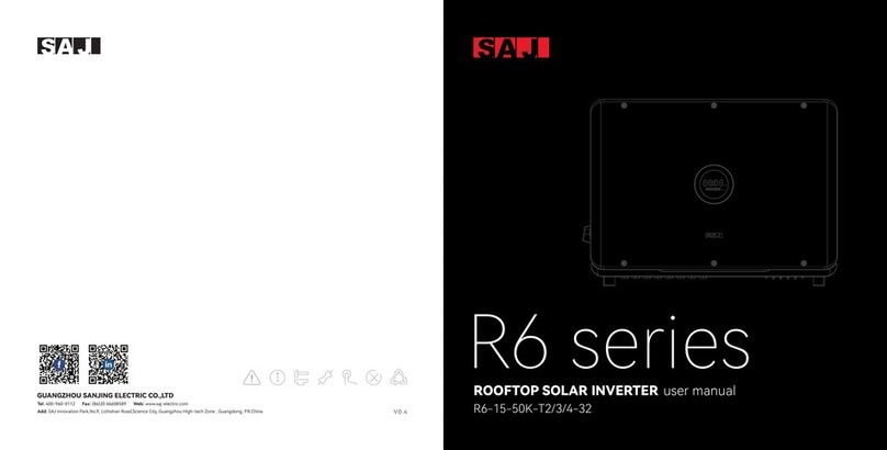
SAJ R6 Series User manual

Tel: 400-960-0112 Fax: (86)20 66608589 Web: www.saj-electric.com
R6 series
R6-3~15K-T2
ROOFTOP SOLAR INVERTER
Add: SAJ Innovation Park,No.9, Lizhishan Road,Science City, Guangzhou High-tech Zone , Guangdong, P.R.China.
GUANGZHOU SANJING ELECTRIC CO.,LTD
V0.4
user manual

ROOFTOP SOLAR INVERTER USER MANUAL

TABLE OF
contents
4. ELECTRICAL CONNECTION----------21
4.1 Safety Instruction -----22
4.2 Specications for Electrical Inteace-----22
4.3 AC Connection-----23
4.4 DC Side Connection-----25
4.5 Communication Connection-----29
5. DEBUGGING INSTRUCTIONS----------33
5.1 Introduction of HMI-----34
5.2.5 Remote Monitoring-----40
1.1 Scope of Application-----02
1.2 Safety-----02
1.2.1 Safety Instruction-----02
1.2.2 Explanations of Symbols-----03
1.2.3 Safety Instructions-----04
2. PRODUCT OVERVIEW----------05
2.1 Specication for Product Model-----07
2.2 Appearance-----07
2.3 Datasheet-----09
3. INSTALLATION INSTRUCTION----------13
3.1 Safety Instructions-----14
3.2 Pre-installation Check-----14
1. SAFETY PRECAUTIONS ----------01
6. FAULT CODE & Troubleshooting----------49
7. RECYCLING & DISPOSAL----------53
5.2 Monitoring Operation-----35
5.2.1 APP Introduction-----35
5.2.2 Local Connection-----36
5.3 Expo Limit Setting-----41
5.4 Self-test-----43
4.6 Sta Up And Shut Down Inveer-----32
4.7 AFCI-----------------32
3.3 The Determination of the
Installation Position-----16
3.4 Mounting Procedure-----18
5.2.3 Account Login-----38
5.2.4 Inveer Setting Review-----40
5.5 Setting Reactive Power Control-----45

1.1 Scope of
Application
1.2 Safety
1.
SAFETY
precautions
· DANGER indicates a hazardous situation, which, if not avoided, will result in death or serious inju.
· WARNING indicates a hazardous situation, which, if not avoided, can result in death or serious inju or moderate inju.
· CAUTION indicates a hazardous condition, which, if not avoided, can result in minor or moderate inju.
· NOTICE indicates a situation that can result in potential damage, if not avoided.
This User Manual describes instructions and detailed procedures for installing, operating,
maintaining, and troubleshooting of the following SAJ on-grid inveers:
Please keep this manual all time available in case of emergency.
R6-3K-T2, R6-4K-T2, R6-5K-T2, R6-6K-T2, R6-8K-T2, R6-10K-T2,
R6-10K-T2-B, R6-12K-T2, R6-15K-T2
DANGER
WARNING
CAUTION
NOTICE
0201
1.2.1 Safety
Instructions
ROOFTOP SOLAR INVERTER USER MANUAL

1.2.2 Explanations of Symbols 1.2.3 Safety Instructions
Symbol
Dangerous electrical voltage
This device is directly connected to public grid, thus all work to the inveer shall only be
carried out by qualied personnel.
Danger to life due to high electrical voltage!
Notice, danger!
This is directly connected with electricity generators and public grid.
Danger of hot suace
An error has occurred
Please go to Chapter 6 “Troubleshooting” to remedy the error.
This device SHALL NOT be disposed of in residential waste
Please go to Chapter 7 “Recycling and Disposal” for proper treatments.
CE Mark
CQC Mark
No unauthorized peorations or modications
Description
There might be residual currents in inveer because of large capacitors. Wait 5 minutes
before you remove the front lid.
The components inside the inveer will release a lot of heat during operation. Do not
touch metal plate housing during operating.
With CE mark & the inveer fullls the basic requirements of the Guideline Governing
Low-Voltage and Electro-magnetic Compatibility.
The inveer complies with the safety instructions from China's Quality Center.
Any unauthorized peorations or modications are strictly forbidden, if any defect or
damage (device/person) occurred, SAJ shall not take any responsibility for it.
DANGER
· There is possibility of dying due to electrical shock and high voltage.
· Do not touch the operating component of the inveer; it might result in burning or death.
· To prevent risk of electric shock during installation and maintenance, please make sure that all AC and DC terminals
are plugged out.
· Do not touch the suace of the inveer while the housing is wet, otherwise, it might cause electrical shock.
· Do not stay close to the inveer while there are severe weather conditions including storm, lighting, etc.
· Before opening the housing, the SAJ inveer must be disconnected from the grid and PV generator; you must wait for
at least ve minutes to let the energy storage capacitors completely discharged after disconnecting from power source.
· The installation, seice, recycling and disposal of the inveers must be peormed by qualied personnel only in
compliance with national and local standards and regulations.
· Any unauthorized actions including modication of product functionality of any form may cause lethal hazard to the
operator, third paies, the units or their propey. SAJ is not responsible for the loss and these warranty claims.
· The SAJ inveer must only be operated with PV generator. Do not connect any other source of energy to the SAJ inveer.
· Be sure that the PV generator and inveer are well grounded in order to protect propeies and persons.
WARNING
· The solar inveer will become hot during operation. Please do not touch the heat sink or peripheral suace during or
sholy after operation.
· Risk of damage due to improper modications.
CAUTION
· Public utility only.
· The solar inveer is designed to feed AC power directly to the public utility power grid; do not connect AC output of the
inveer to any private AC equipment.
NOTICE
Risk of e l e c tric shoc k ! O n l y
authorized personnel are allowed
to do disassembly, modication or
maintenance. Any resulting defect
or damage (device/person) is not
coverde by SAJ guaranty.
ATTENTION!
03 04
ROOFTOP SOLAR INVERTER USER MANUAL
Figure 2.1
System oveiew
2.
PRODUCT
oveiew
R6 series
R6 Series Solar Inverter
PV Array
On-grid Load
AC Distribution Box Grid
Wi-Fi/ 4G/ Ethernet
05 06
R6-3~15K-T2 products are grid-tied three phase inveers without transformers, and the
inveers are impoant components of grid-tied solar power systems.
The R6 inveer conves the DC generated by solar panels into AC which is in accordance
with the requirements of public grid and send the AC into the grid, Figure 2.1 shows the
structural diagram of the typical application system.
APP
WebeSolar Poal
ROOFTOP SOLAR INVERTER USER MANUAL

2.2 Appearance
2.1 Specication
for Product Model
Figure 2.2
Dimensions of
R6-3K/4K/5K/6K/8K/10K/12K/15K-T2-B
07
① R6 represents for product name.
② XK represents rated power XkW of inveer, for example 4K means 4kW.
③ T means three phase; X represents the inveer has the function of X MPP trackers.
④ B indicates this model is ONLY applicable to Belgium.
R6 – XK – TX– B
① ② ③
ROOFTOP SOLAR INVE TER USER MANUAL
R
08
④

2.3 Datasheet
R6-3K-T2 R6-4K-T2 R6-6K-T2
1100
160-950
600
180
150
16/16
19.2/19.2
2
1/1
3L+N+PE, 220/380, 230/400, 240/415; 180-280/312-485
50, 60/45-55, 55-65
< 3%
0.8 leading~0.8 lagging
3/3
Integrated
Integrated
Integrated
Integrated
Integrated
Integrated
Integrated
4500 6000 9000
3000
3300
4.4
5.0
Model
Input (DC)
Max. PV Array Power [Wp]@STC
Max. Input Voltage [V]
MPP Voltage Range [V]
Nominal Input Voltage [V]
Start-up Voltage [V]
Min. Input Voltage[V]
Max. Input Current [A]
Max. Short-Circuit Current[A]
Number of MPP Trackers
Number of Strings per MPP Tracker
Output (AC)
Rated AC Output Power [W]
Max. Apparent Power [VA]
Rated AC Output Current [A]@230Vac
Max. AC Output Current [A]
Nominal AC Voltage/ Range [V]
Nominal AC Grid Frequency/ Range [Hz]
Total Distortion Harmonic [THDi]
Power Factor
Feed-in Phases/AC Connection Phases
Efficiency
Max. Efficiency
Euro Efficiency
Protection
Overvoltage Protection
DC Insulation Rsistance Detection
DCI monitoring
GFCI monitoring
Grid monitoring
AC Short Circuit Current Protection
AC Grounding Detection
R6-3K/4K/5K/6K-T2
1009
4000
4400
5.8
6.7
6000
6600
8.7
10.0
5000
5500
7.3
8.4
R6-5K-T2
7500
ROOFTOP SOLAR INVERTER USER MANUAL
98.2%
97.8%
98.5%
98.2%
98.5%
98.2%
98.5%
98.2%
Integrated
Integrated
Integrated
AFD
Optional
Plug-in connector
MC4/H4
LED+APP
RS232(USB)+RS485(RJ45)+DRM
Wi-Fi/Ethernet/4G(Optional)
24/7 (Optional)
Non-isolated
<1
-40℃~+60℃ (45℃ to 60℃ with derating)
Natural Convection
0%~100% non-condensing
4000m (>3000m power derating)
<35
IP65
Wall Mounting
391*532*190
15
5(Standard)/10/15/20(Optional)
EN62109-1/2, EN61000-6-1/2/3/4, EN50438, EN50549, C10/11, IEC62116, IEC61727, RD1699,
RD413, UNE 206006, UNE 206007, NTS, CEI 0-16, CEI O-021, AS4777.2, NBR16149,
NBR 16150 VDE-AR-N 4015, VDE 0126-1-1
R6-3K-T2 R6-4K-T2 R6-6K-T2R6-5K-T2
Overheating protection
Anti-islanding Protection
AFCI Protection
Interface
AC Connection
DC Connection
Display
Communication Port
Communication Mode
Load Monitoring
General Data
Topology
Consumption at Night [W]
Operating Temperature Range
Cooling Method
Ambient Humidity
Max. Operating Altitude [m]
Noise [dBA]
Ingress Protection
Mounting
Dimensions [H*W*D] [mm]
Weight [kg]
Warranty [Year]
Certifications
Model
DC surge protection
AC surge protection

1211
ROOFTOP SOLAR INVERTER USER MANUAL
Integrated
Integrated
Integrated
AFD
Optional
Plug-in connector
MC4/H4
LED+APP
RS232(USB)+RS485(RJ45)+DRM
Wi-Fi/Ethernet/4G(Optional)
24/7 (Optional)
Non-isolated
<1
-40℃~+60℃ (45℃ to 60℃ with derating)
Natural Convection
0%~100% non-condensing
4000m (>3000m power derating)
<35
IP65
Wall Mounting
391*532*190
15
5(Standard)/10/15/20(Optional)
EN62109-1/2, EN61000-6-1/2/3/4, EN50438, EN50549, C10/11, IEC62116, IEC61727, Rd1699,
RD413, UNE 206006, UNE 206007, NTS, CEI 0-16, CEI O-021, AS4777.2, NBR16149,
NBR 16150 VDE-AR-N 4015, VDE 0126-1-1
R6-8K-T2 R6-10K-T2 R6-15K-T2R6-12K-T2
Overheating protection
Anti-islanding Protection
AFCI Protection
Interface
AC Connection
DC Connection
Display
Communication Port
Communication Mode
Load Monitoring
General Data
Topology
Consumption at Night [W]
Operating Temperature Range
Cooling Method
Ambient Humidity
Max. Operating Altitude [m]
Noise [dBA]
Ingress Protection
Mounting
Dimensions [H*W*D] [mm]
Weight [kg]
Warranty [Year]
Certifications
Model
DC surge protection
AC surge protection
R6-8K-T2 R6-10K-T2 R6-15K-T2
1100
160-950
600
180
150
16/16
19.2/19.2
2
1/1
3L+N+PE, 220/380, 230/400, 240/415; 180-280/312-485
50, 60/45-55, 55-65
< 3%
0.8 leading~0.8 lagging
3/3
Integrated
Integrated
Integrated
Integrated
Integrated
Integrated
Integrated
12000 15000 22500
8000
8800
11.6
13.4
Model
Input (DC)
Max. PV Array Power [Wp]@STC
Max. Input Voltage [V]
MPP Voltage Range [V]
Nominal Input Voltage [V]
Start-up Voltage [V]
Min. Input Voltage[V]
Max. Input Current [A]
Max. Short-Circuit Current[A]
Number of MPP Trackers
Number of Strings per MPP Tracker
Output (AC)
Rated AC Output Power [W]
Max. Apparent Power [VA]
Rated AC Output Current [A]@230Vac
Max. AC Output Current [A]
Nominal AC Voltage/ Range [V]
Nominal AC Grid Frequency/ Range [Hz]
Total Distortion Harmonic [THDi]
Power Factor
Feed-in Phases/AC Connection Phases
Efficiency
Max. Efficiency
Euro Efficiency
Protection
Overvoltage Protection
DC Insulation Rsistance Detection
DCI monitoring
GFCI monitoring
Grid monitoring
AC Short Circuit Current Protection
AC Grounding Detection
R6-8K/10K/12K/15K-T2-B
10000
11000
14.5
16.7
15000
15000
21.8
22.8
12000
13200
17.4
20.0
R6-12K-T2
18000
98.6%
97.3%
98.6%
98.3%
98.6%
98.4%
98.6%
98.4%
R6-10K-T2-B
15000
10000
10000
14.5
15.2
98.6%
98.3%
R6-10K-T2-B

3.
INSTALLATION
instruction
DANGER
NOTICE
· Dangerous to life due to potential re or electricity shock.
· Do not install the inveer near any inammable or explosive items.
· This inveer will be directly connected with HIGH VOLTAGE power generation device; the installation must be peor
med by qualied personnel only in compliance with national and local standards and regulations.
· This equipment meets the pollution degree III.
· Inappropriate or the harmonized installation environment may jeopardize the life span of the inveer.
· Installation directly exposed under intensive sunlight is not recommended.
· The installation site must be well ventilated.
1413
ROOFTOP SOLAR INVERTER USER MANUAL
3.1
Safety Instructions
3.2
Pre-installation Check
Although SAJ’s inveers have thoroughly tested and checked before delive, it is
unceain that the inveers may suer damages during transpoation. Please
check the package for any obvious signs of damage, and if such evidence is present,
do not open the package and contact your dealer as soon as possible
3.2.1
Check the Package

1615
ROOFTOP SOLAR INVERTER USER MANUAL
3.3 Determine the
installation method and position
(1) The equipment employs natural convection cooling, and it can be installed indoor
or outdoor.
(2)Mount veically or tilted backwards by max. 15°. Never install the inveer tilted forwards,
sideways, horizontally or upside down.
Figure 3.1
Mounting Method
3.2.2
Scope of Delive
Please contact after sales if there is missing or damaged components.
R6-10K-T2 Inveer*1 Rear Panel*1 Documents
expansion bolt & wahser*3 M5*12 screw*1 Communication
module*1 (Optional)M6*50 screw*3
PV connector*4
The documents include the user manual, quick installation guide and packaging list.
Plug-in connector*1 RJ45 plug*1
(3)Considering convenience for maintenance, please install the equipment at eye level.
(4) When mounting the inveer, please consider the solidity of wall for inveer, including
accessories, make sure the wall has enough strength to hold the screws and bear the weight
of products. Please ensure the mounting bracket mounted tightly.

Ensure air circulation at the installation point. If several units are installed in the same area,
the installation clearance requirements as shown in Figure 3.2 should be followed in order to
provide suitable air circulation conditions for the unit.
Figure 3.2
R6-3K/4K/5K/6K/8K/10K/12K/15K-T2-B
Mounting Clearance
3.4
Mounting
Procedure (1) The mounting position should be marked as below.
Figure 3.3
R6-3K/4K/5K/6K/8K/10K/12K/15K-T2-B
Hanging plate size
1817
Unit: mm
Figure 3.4
R6-3K/4K/5K/6K/8K/10K/12K/15K-T2-B
Drilling holes position
ROOFTOP SOLAR INVERTER USER MANUAL
(2) Drill holes and fix screw fixing seat
Follow the given guides, drill 3 holes in the wall (in conformity with position marked
in Figure3.4), and then place expansion tubes in the holes using a rubber mallet.

Figure 3.7
Securing the screws
2019
(3) Fix screw and hanging plate
Fix the hanging plate in the installation position with M6*50mm hexagon
screw as shown in Figure 3.5.
Figure 3.5
Securing the plate
Figure 3.6
Mounting inveer
Unit: mm
ROOFTOP SOLAR INVERTER USER MANUAL
(4) Mount the inverter
Carefully mount the inveer to the mounting bracket. Make sure that the rear
pa of the equipment is closely mounted to the mounting bracket.
Then x the inveer and hanging plate with M5*12mm external hexagon screw.

4.
ELECTRICAL
NOTICE
4.1
Safety Instruction
connection
4.2
Specications for
Electrical Inteace
Table 4.1
Inteace specication
· Dangerous to life due to potential re or electricity shock.
· When power-on, the equipment should in conformity with national rules and regulations.
· The direct connection between the inveer and high voltage power systems must be operated by qualied
technicians in accordance with local and national power grid standards and regulations.
· The PV arrays will produce lethal high voltage when exposed to sunlight.
Electrical connection must only be operated on by professional technicians. Please keep in
mind that the inveer is a bi-power supply equipment. Before connection, necessa
protective equipment must be employed by technicians including insulating gloves, insulating
shoes and safety helmet.
DANGER
· Electrical connection should in conformity with proper stipulations, such as stipulations for cross-sectional area of
conductors, fuse and ground protection.
· The oveoltage catego on DC input po is , on AC output po is .
2221
ROOFTOP SOLAR INVERTER USER MANUAL
Code
A
B
C
D
E
F
G
Name
DC Switch
DC Input
Relief Valve
RS232 Communication (Wi-Fi/ 4G)
RS485 Communication+ DRM
AC Output
Grounding po

23 24
ROOFTOP SOLAR INVERTER USER MANUAL
4.3
AC side electrical
connection
Type Cross-sectional area of cables(mm²)
6.0-10.0
Table 4.2
Ac circuit breaker specications are recommended
If the grid-connection distance is too far, please select AC cable with larger diameter as per
the actual condition.
Scope Recommended value
6.0R6-3K/4K/5K/6K/8K/10K/12K/15K-T2
(1) For the grounding protection of the inveer, inse the M5*12mm outer hexagon screw
clockwise through the OT terminal of the GND cable into the grounding po of the inveer
shell, and tighten the screw.
Figure 4.2
Inveer ground protection
Type AC circuit breaker specications
16A
20A
32A
R6-3K/4K/5K/6K-T2
R6-8K/10K-T2
R6-12K/15K-T2
Please install a 4P circuit breaker to ensure the inveer is able to disconnect from grid safely.
The inveer is integrated with a RCMU, however, an external RCD is needed to protect the
system from tripping, either type A or type AC RCD is compatible with the inveer.
The integrated leakage current detector of inveer is able to detect the real time external
current leakage. When a leakage current detected exceeds the limitation the inveer will be
disconnected from grid quickly, if an external leakage current device is connected, the action
current should be 300mA or higher.
Table 4.3
Recommended AC cable specication
(2) Take the outdoor ve-core cable, peel o 50mm of the outer skin, and expose 10mm of
the single-strand core. Then pass the AC wire through the AC waterproof sheath.
(3) When connecting cables, the AC cables should be tightened and xed with a hex wrench
according to the wiring labels L1, L2, L3, N and PE .
Figure 4.3
AC Cable Connection
Figure 4.4
Connect AC cables to AC connectors
Note: Recommended conductor cross-sectional area of additional grounding cable is 6-10mm².

2625
4.4
DC Side Connection
Cross-sectional area of cables(mm²)
Outside diameter of the cables(mm)
Recommended value
4.0
Scope
4.0~6.0
Table 4.4
Recommended specications of DC cables
4.2~5.3
ROOFTOP SOLAR INVERTER USER MANUAL
DC connector is made up of one positive connector and one negative connector
Figure 4.7
Negative connector
· Please place the connector separately after unpacking in order to avoid confusion for connection of cables.
· Please connect the positive connector to the positive side of the solar panels, and connect the negative
connector to the negative side of the solar side. Be sure to connect them in right position.
NOTICE
Figure 4.9
Inseing cables to lock screws
3.Assembly the positive and negative cables with corresponding crimping pliers.
Connecting Procedures:
Figure 4.8
Striping o the insulation skin of cables
1. Loosen the lock screws on positive and negative connector.
2. Strip the insulation of the positive and negative cables with 8-10mm length.
Figure 4.6
Positive connector
· Make sure the PV array is well insulated to ground before connecting it to the inveer.
WARNING
(4) After checking the wiring, tighten the waterproof gland of AC connector respectively.
Figure 4.5
AC connector installation

28
27
ROOFTOP SOLAR INVERTER USER MANUAL
4.Inse the positive and negative cable into positive and negative connector. Gently pull the
cables backward to ensure rm connection.
Figure 4.11
Securing the connectors
5. Fasten the lock screws on positive and negative connectors.
Figure 4.13
Plug in PV connectors
7.Connect the positive and negative connectors into positive and negative DC input
terminals of the inveer, a “click” should be heard or felt when the contact cable
assembly is seated correctly.
· Before inse the connector into DC input terminal of the inveer, please make sure that the DC switch of the
inveer is OFF.
· Please use the original terminal to install.
NOTICE
Figure 4.12
DC switch
6.Make sure the DC switch is at OFF position
Figure 4.10
Inseing crimped cables to connectors

29
R6 inveer is standardly equipped with a RS485 inteace, a DRM inteace and
a RS232 inteace
Figure 4.9
RS485 pin
4.5
Communication
Connection
Table 4.6
RS485 pin po denition
Pin Number
1
2
3
4
5
6
7
8
Description
NC
NC
NC
NC
NC
NC
RS485-A
RS485-B
Eect
Transmission RS485 dierential signal
Figure 4.10
RS232 pin
Table 4.5
USB pin po denition
Pin Number
1
2
3
4
Description
+5V
RS-232 TX
RS-232 RX
GND
Eect
Power supply
Send data
Receive data
Ground wire
30
ROOFTOP SOLAR INVERTER USER MANUAL
1 2 3 4
1 2 3 4 5 6 7 8
2.Inse the cable through the sealing nut of cable gland
Figure 4.12
RJ45 plug
Figure 4.13
Inseing cables
Figure 4.14
Inseing rubber seal
Pin NO.
1
2
3
4
5
6
7
8
Name
NC
NC
NC
NC
REF GEN
COM LOAD
NC
NC
Table 4.6
Demand Response Modes (DRM)
To comply with Australian and New Zealand safety requirements, the DRMs terminals should be
connected. DRM0 is suppoed. A RJ45 plug is being used as the inveer DRED connection.
Table 4.7
DRM0 mode
Mode
DRM0
Corresponding pins
5 & 6
Requirement
The inveer is on standby mode
Proceed as follow to connect the RS485 cables to the inveer
1.(Optional) The RS485 cable is prepared by user. It is recommended to strip the RS485 cable
and Ethernet wire insulation. Inse the stripped Ethernet wires in correct order into the RJ45
plug (please refer to g 5.14 and table 5.5 for order) and crimp it with a crimper.
3.Install the rubber seal onto cables
1 2 3 4 5 6 7 8
Figure 4.11
DRM pin

31
4.Inse the RJ45 cables into the corresponding pos
Figure 4.15
Inseing RJ45 cables
4.6
Sta up and Shut
down Inveer
Figure 4.17
Installing communication module
Plug in the communication module to 4G/WIFI po and secure the module by rotating
the nut.
1. USB inteace could be externally connected with eSolar AIO3 module, for operation in
details please refer to eSolar AIO3 module Quick Installation Guide in https://www.saj-
electric.com/.
2. USB inteace could be externally connected with eSolar 4G module, for operation in
details please refer to eSolar 4G module Quick Installation Guide in https://www.saj-
electric.com/.
3. USB inteace could be externally connected with eSolar WiFi module, for operation in
details please refer to eSolar WiFi module Quick Installation Guide in https://www.saj-
electric.com/.
32
ROOFTOP SOLAR INVERTER USER MANUAL
1. Follow the installation standard from previous chapter strictly to connect the photovoltaic
panels and AC power grid to inveer.
2. Using multimeter to check whether AC side and DC side voltage have met the inveer sta
voltage.
3. Turn ON DC switch (if applicable), LED indicators will be lit up.
4. Select count grid code through the APP(See Chapter 5 Monitoring Operations), please
contact your local grid operator for which region toselect. Inveer will be in self-testing ,
if inveer has met all the grid connecting condition, inveer will connect to grid and generate
power automatically.
1. Automatically shut down, when the solar light intensity is not strong enough during sunrise
and sunset or the output voltage of photovoltaic system is less than the minimum input
power of inveer, inveer will shut down automatically.
2. Shut down manually, disconnect AC side circuit breaker rst, if multiple inveers are
connected, disconnect the minor circuit breaker prior to disconnection of main circuit
breaker. Disconnect the DC switch after inveer has repoed grid connection lost alarm.
The inveer is equipped with arc-fault circuit interrupter (AFCI). With AFCI protection, when
there is an arc signal on the DC side due to aging of the cable or loose contact, R6 series can
quickly detect and cut o the power to prevent re, making the PV system run more safely.
Figure 4.16
Inseing RJ45 cables
5.Secure the cable gland by rotating sealing nut and plug the cable gland to communication
po of inveer
4.7
AFCI (Optional)
4.6.1
Sta Up the Inveer
4.6.2
Shut Down the Inveer

5.
DEBUGGING
instructions
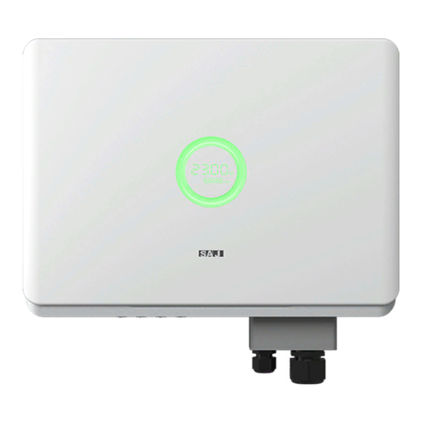
Introduction to man-machine Inteace
Figure 5.1
Human-Machine Inteace
3433
5.1
ROOFTOP SOLAR INVERTER USER MANUAL
Other manuals for R6 Series
5
This manual suits for next models
9
Table of contents
Other SAJ Inverter manuals

SAJ
SAJ H2 Series User manual

SAJ
SAJ R6 Series User manual

SAJ
SAJ S350 Series User manual

SAJ
SAJ R6 Series User manual

SAJ
SAJ R5-5K-T2 User manual

SAJ
SAJ Suntrio-TL Series User manual

SAJ
SAJ R6 Series User manual

SAJ
SAJ H2 Series User manual

SAJ
SAJ R5-3.6K-S2 User manual

SAJ
SAJ Suntrio Plus Series User manual

SAJ
SAJ 8000B series User manual

SAJ
SAJ Sununo-TL Series User manual

SAJ
SAJ Suntrio-TL8K User manual

SAJ
SAJ eSolar RS485 User manual

SAJ
SAJ 8000m-2SR4GH User manual

SAJ
SAJ AS1-3KS-5.1 User manual

SAJ
SAJ R6 Series User manual

SAJ
SAJ AS1-3KS-5.1 User manual

SAJ
SAJ R6 S2 Series User manual

SAJ
SAJ Sununo-TL Series User manual