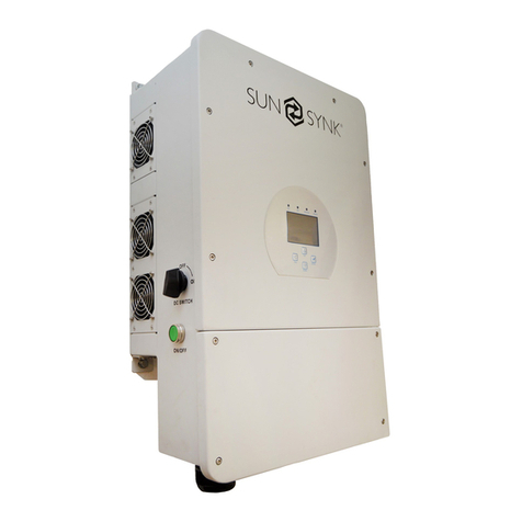
Ingecon Sun 250 M220 Indoor User manual

INGECON SUN PowerMax
Indoor
Installation manual

AAV2000IKI01_C
09/2012
Ingeteam Power Technology, S.A.
Energy
Avda. Ciudad de la Innovación, 13
31621 SARRIGUREN (Navarra) - Spain
Tel.: +34 948 28 80 00
Fax.: +34 948 28 80 01
e-mail: solar.energy@ingeteam.com
Service Call Center: +34 948 698 715
The copy, distribution or use of this document or of its content requires written authorisation. Any breach thereof will
be reported for damages. All rights reserved including those of patent rights or design registration.
The conformity of the document content with the hardware described has been checked. However, discrepancies may
exist. Liability will not be assumed for total concordance. The information contained in this document is regularly
reviewed and it is possible that there may be changes in subsequent editions. Other functions may be available which
are not covered by this document.
This document may be changed.

AAV2000IKI01 iii
Installation manual Ingeteam
Important safety precautions
This manual contains important instructions for the installation, handling and use of the following models:
INGECON SUN 250 M220 Indoor
INGECON SUN 315 M275 Indoor
INGECON SUN 365 M320 Indoor
INGECON SUN 375 M220 Indoor
INGECON SUN 400 M345 Indoor
INGECON SUN 420 M360 Indoor
INGECON SUN 500 M220 Indoor
INGECON SUN 500 M275 Indoor
INGECON SUN 550 M320 Indoor
INGECON SUN 600 M345 Indoor
INGECON SUN 625 M275 Indoor
INGECON SUN 630 M360 Indoor
INGECON SUN 730 M320 Indoor
INGECON SUN 800 M345 Indoor
INGECON SUN 840 M360 Indoor
and any models derived from these.
Read these instructions carefully and keep them in a safe place.
General warnings
The operations described in the manual may be performed only by qualified personnel.
All applicable safety-related legislation for electrical work must be complied with. Danger of electric
shock.
The entire manual must be read and understood in full prior to manipulating, installing or operating
the unit.
The status of qualified personnel referred to in this manual will be, as a minimum, that which meets
all the standards, regulations and laws regarding safety applicable to the tasks of installing and oper-
ating this unit.
The responsibility for designating qualified personnel will always fall to the company to which the
personnel belong. It is necessary to decide which workers are suitable or not for carrying out specific
work to preserve their safety at the same time as complying with occupational safety legislation.
These companies are responsible for providing appropriate training in electrical equipment to their
personnel and for familiarising them with the contents of this manual.
Opening the doors to the different cubicles does not imply lack of voltage inside.
Only qualified personnel may open them, following the instructions in this manual.
The risk of electric shock exists even after disconnecting from the grid, the PV array and the auxiliary
supplies.
Compliance with the safety instructions set out in this manual or in the suggested legislation does
not imply exemption from other specific standards for the installation, place, country or other circum-
stances that affect the inverter.

AAV2000IKI01
iv
Installation manualIngeteam
Carry out all control and handling without voltage.
As a minimum security measure in this operation, the so-called five golden rules should always be
followed:
1. Disconnect
2. Prevent any possible resupply
3. Check there is no voltage
4. Ground and short circuit the equipment
5. Protect from live elements, if any, and put up safety signs around the work zone.
Until these five steps are completed, the work area cannot be considered voltage-free and any work
performed will be considered to be work on live equipment.
Following is a list of the basic obligatory safety standards for each country:
• RD 614/2001 in Spain.
• CEI 11-27 in Italy.
• DIN VDE 0105-100 and DIN VDE 1000-10 in Germany.
• UTE18-510 in France.
Category III - 1000-Volt measuring instruments must be used for checking for the absence of voltage.
Ingeteam accepts no liability for any damages caused by improper use of the equipment.

AAV2000IKI01 v
Installation manual Ingeteam
Potential hazards for people
Bear in mind the following warnings concerning personal safety.
DANGER: Electric shock.
The equipment may remain charged after disconnecting the PV array and mains power.
Carefully follow the mandatory steps in the manual for removing the voltage.
DANGER: Explosion.
There is a very low risk of explosion in very specific cases of malfunction.
The casing will protect people and property from the explosion only if it is correctly closed.
DANGER: Crushing and joint injuries.
Always follow the indications in the manual on moving and placing the unit.
The weight of this unit can cause lesions, serious injury and even death if not handled correctly.
DANGER: High temperature.
The flow of air from the side and top outlets can reach high temperatures which can cause injury to
people exposed.
The back and side of the unit act as a radiator. Do not touch, danger of severe burns.

AAV2000IKI01
vi
Installation manualIngeteam
Potential hazards for the equipment
Bear in mind the following warnings for the protection of your equipment.
CAUTION: Ventilation.
The unit requires quality air flow while it is operating.
Keeping the unit in the upright position and the inlets free of obstacles is essential for this air flow
to reach the inside.
CAUTION: Connections.
After all duly authorised handling, check that the inverter is ready to start operation. Only after this
can it be connected following the instructions in the manual.
CAUTION: Electrical damage.
Do not touch boards or electronic components. The most sensitive components can be damaged or
destroyed by static electricity.
CAUTION: Operation.
Do not disconnect or connect any terminal while the unit is operating. Disconnect and check for
absence of voltage first.
Personal protection equipment (PPE)
Use all items comprising the personal protection equipment.
In Chapter “4. Safety instructions” contains references to the use of this equipment depending on the situation.
The standard personal protective equipment is:
• Safety goggles for mechanical hazards
• Safety goggles for electrical hazards
• Safety footwear
• Helmet

AAV2000IKI01 vii
Installation manual Ingeteam
Table of Contents
1. Overview ...............................................................................................................................................10
1.1. Equipment description ....................................................................................................................10
1.1.1. Models ..................................................................................................................................10
1.1.2. Options .................................................................................................................................11
1.1.3. Compositions .........................................................................................................................11
1.2. Compliance with regulations ............................................................................................................14
1.2.1. CE marking ............................................................................................................................14
Low Voltage Directive ...................................................................................................................14
Electromagnetic Compatibility Directive .........................................................................................14
2. System description .................................................................................................................................14
2.1. Location ........................................................................................................................................14
2.1.1. Environment ...........................................................................................................................14
2.1.2. IP rating ................................................................................................................................15
2.1.3. Ambient temperature ..............................................................................................................15
2.1.4. Atmospheric conditions ...........................................................................................................15
2.1.5. Contamination class ...............................................................................................................15
2.1.6. Acoustic contamination ...........................................................................................................15
2.1.7. Ventilation ..............................................................................................................................15
2.1.8. Support surface and fastening .................................................................................................18
2.2. Environmental characteristics ..........................................................................................................20
2.3. Characteristics of the electrical installation .......................................................................................20
2.4. EMC requirements ..........................................................................................................................20
3. Operating, conservation and transport conditions .......................................................................................21
3.1. Symbols ........................................................................................................................................21
3.2. Equipment reception ......................................................................................................................21
3.3. Handling and unpacking .................................................................................................................22
3.4. Moving the equipment ....................................................................................................................23
3.5. Storage .........................................................................................................................................24
3.6. Conservation ..................................................................................................................................25
3.7. Waste handling ...............................................................................................................................25
4. Safety instructions .................................................................................................................................27
4.1. Symbols ........................................................................................................................................27
4.2. General safety precautions ..............................................................................................................27
4.3. General .........................................................................................................................................28
4.3.1. General risks existing and preventive measures ..........................................................................28
4.3.2. Additional risks and measures in handling tasks .......................................................................29
4.4. Type of tasks to be carried out .........................................................................................................29
4.4.1. Inspection tasks .....................................................................................................................29
4.4.2. Control tasks .........................................................................................................................29
4.4.3. Handling tasks .......................................................................................................................29
4.4.4. Personal Protection Equipment (PPE) .......................................................................................30
4.5. Cabinets for the various models .......................................................................................................31
4.5.1. DC module (cubicle A) ............................................................................................................32
4.5.2. Power modules 1-2 and 3-4 (cubicles B and C) .........................................................................32
4.5.3. AC Module (cubicle D) ...........................................................................................................33
5. Installation ............................................................................................................................................35
5.1. General requirements for installation ................................................................................................35
5.2. Fixing the unit to the floor ...............................................................................................................35
5.3. Requirements for transformers and insulation monitor ........................................................................36
5.3.1. Grid connection transformer ....................................................................................................36
5.3.2. Auxiliary transformer ..............................................................................................................37
5.4. Electrical connection ......................................................................................................................38
5.4.1. Description of cable inlets .......................................................................................................40
Access points common to all INGECON SUN PowerMax units ..........................................................45
5.4.2. Description of cabling connections ...........................................................................................46
5.4.3. Order of connecting the unit ................................................................................................... 48
5.4.4. System wiring diagram ........................................................................................................... 48

AAV2000IKI01
viii
Installation manualIngeteam
5.4.5. Insulation fault contact / grid connection indicator .....................................................................50
5.4.6. Access to auxiliary connections ................................................................................................51
5.4.7. Connection for communication via RS-485 serial port ................................................................52
5.4.8. Connection for communication via modem-GSM/GPRS + RS-485 ...............................................52
5.4.9. Connection for Ethernet communication ...................................................................................52
5.4.10. Connection for fibre optic communication ...............................................................................53
5.4.11. Ground connections ..............................................................................................................53
5.4.12. Connecting the auxiliary supply ..............................................................................................53
5.4.13. Grid connection ....................................................................................................................54
5.4.14. AC intake neutral connection .................................................................................................56
5.4.15. Connecting to the PV array ....................................................................................................57
5.5. Equipment configuration .................................................................................................................58
5.5.1. CAN number setting of an electronics block ..............................................................................58
5.5.2. Configuring the Modbus Node of an electronics block ................................................................58
5.5.3. Synchronization of electronics blocks in units connected to the same inverter...............................59
5.6. Available kits .................................................................................................................................60
5.6.1. Grounding kit .........................................................................................................................60
5.6.2. Remote triggering kit ..............................................................................................................62
6. Commissioning ......................................................................................................................................63
6.1. Equipment inspection .....................................................................................................................63
6.1.1. Inspection..............................................................................................................................63
6.1.2. Shutting down........................................................................................................................63
6.2. Start-up ........................................................................................................................................63
6.2.1. Start-up ................................................................................................................................64
6.2.2. Checking and measurement ....................................................................................................64
7. Preventive maintenance ...........................................................................................................................65
7.1. Maintenance tasks .........................................................................................................................65
8. Display control .......................................................................................................................................68
8.1. Keypad and LEDs ...........................................................................................................................68
8.2. Display ..........................................................................................................................................69
8.3. Main menu ....................................................................................................................................70
8.4. Monitoring .....................................................................................................................................70
8.5. Reasons for shutdown .....................................................................................................................72
8.6. Settings ........................................................................................................................................73
Date and Time ............................................................................................................................73
Inverter number change ...............................................................................................................73
Language ...................................................................................................................................73
Grid quality .................................................................................................................................73
Ground connection ......................................................................................................................73
Connection time ..........................................................................................................................73
Total reset ..................................................................................................................................74
Other adjustments .......................................................................................................................74
Change NumCAN ........................................................................................................................74
8.7. Inverter data ..................................................................................................................................74
8.8. Change inverter number ..................................................................................................................74
9. Troubleshooting ......................................................................................................................................75
9.1. LED messages ...............................................................................................................................75
9.1.1. Green LED .............................................................................................................................75
Slow flashing ..............................................................................................................................75
Fast flashing ...............................................................................................................................75
Steady light ................................................................................................................................75
9.1.2. Orange LED ...........................................................................................................................76
Fast flashing ...............................................................................................................................76
9.1.3. Red LED................................................................................................................................76
Steady light ................................................................................................................................76
9.2. List of alarms and reasons for shutdown ...........................................................................................77
9.3. Inverter alarms due to protections ....................................................................................................78
9.4. Action protocol for responding to incidents........................................................................................78
9.4.1. Voltage and/or frequency out of range .......................................................................................79
9.4.2. Temperature ..........................................................................................................................81

AAV2000IKI01 ix
Installation manual Ingeteam
9.4.3. AC circuit protection .............................................................................................................. 83
9.4.4. Reason for contactor shutdown ................................................................................................86
9.4.5. DC circuit protections .............................................................................................................87
9.4.6. Insulation fault ...................................................................................................................... 88
9.4.7. Manual shutdown .................................................................................................................. 88
9.4.8. Thermomagnetic circuit breaker Q2 .........................................................................................89
9.5. Replacing the electronics block ........................................................................................................89
9.6. Replacing varistors in the intake board .............................................................................................91
9.7. Description of terminal strip .............................................................................................................92

AAV2000IKI01
10
Installation manualIngeteam
1. Overview
The purpose of this manual is to describe the INGECON SUN PowerMax unit and to give appropriate information for
its correct receipt, installation, start-up, operation and maintenance.
1.1. Equipment description
An inverter is a circuit used to convert direct current to alternating current. The function of the INGECON SUN
PowerMax units is to convert the direct current generated by photovoltaic solar panels to alternating current and so
enable it to be fed to the electricity grid.
1.1.1. Models
The main models in the INGECON SUN PowerMax range are:
INGECON SUN 250 M220 Indoor
INGECON SUN 315 M275 Indoor
INGECON SUN 365 M320 Indoor
INGECON SUN 375 M220 Indoor
INGECON SUN 400 M345 Indoor
INGECON SUN 420 M360 Indoor
INGECON SUN 500 M220 Indoor
INGECON SUN 500 M275 Indoor
INGECON SUN 550 M320 Indoor
INGECON SUN 600 M345 Indoor
INGECON SUN 625 M275 Indoor
INGECON SUN 630 M360 Indoor
INGECON SUN 730 M320 Indoor
INGECON SUN 800 M345 Indoor
INGECON SUN 840 M360 Indoor
Some INGECON SUN PowerMax models also feature a modified version of the same. The modification consists of
removing the AC module and passing each of its connections to the bottom of the power modules. This modification
is known as NAC.
INGECON SUN PowerMax inverters may be based on five power modules, depending on the model. The various power
modules are:
• 125 kW power module and output voltage of 220 V between phases
• 156 kW power module and output voltage of 275 V between phases
• 183 kW power module and output voltage of 320 V between phases
• 200 kW power module and output voltage of 345 V between phases
• 210 kW power module and output voltage of 360 V between phases
Below you will see the available models and their variants in detail.
Power module Model Variant
125 kW and output voltage of
220 V between phases
INGECON SUN 250 M220 Indoor
INGECON SUN 375 M220 Indoor INGECON SUN 375 M220 Indoor NAC
INGECON SUN 500 M220 Indoor INGECON SUN 500 M220 Indoor NAC
156 kW and output voltage of
275 V between phases
INGECON SUN 315 M275 Indoor
INGECON SUN 500 M275 Indoor INGECON SUN 500 M275 Indoor NAC
INGECON SUN 625 M275 Indoor INGECON SUN 625 M275 Indoor NAC
183 kW and output voltage of
320 V between phases
INGECON SUN 365 M320 Indoor
INGECON SUN 550 M320 Indoor INGECON SUN 550 M320 Indoor NAC
INGECON SUN 730 M320 Indoor INGECON SUN 730 M320 Indoor NAC
200 kW and output voltage of
345 V between phases
INGECON SUN 400 M345 Indoor
INGECON SUN 600 M345 Indoor INGECON SUN 600 M345 Indoor NAC
INGECON SUN 800 M345 Indoor INGECON SUN 800 M345 Indoor NAC

AAV2000IKI01 11
Installation manual Ingeteam
Power module Model Variant
210 kW and output voltage of
360 V between phases
INGECON SUN 420 M360 Indoor
INGECON SUN 630 M360 Indoor INGECON SUN 630 M360 Indoor NAC
INGECON SUN 840 M360 Indoor INGECON SUN 840 M360 Indoor NAC
1.1.2. Options
All models in the INGECON SUN PowerMax range can incorporate the following options:
• AC activator kit
• 1000 VDC kit*
* Consult Ingeteam Customer Service.
1.1.3. Compositions
Different configurations are possible by combining the various INGECON SUN PowerMax models with the various
options available.
INGECON SUN 250 M220 Indoor, 315 M275 Indoor, 365 M320 Indoor, 400 M345 Indoor and 420 M360
Indoor
These units include:
• 2 thermomagnetic circuit breakers on the AC side
• 2 overvoltage protectors on the AC side
• 2 electronics blocks
• 2 MPPT trackers
• 2 fused isolating switches, 1 for each PV array
DC Power
module 1
Power
module 2 AC
These units can incorporate the PIB kit for Italy, which does not change its outside appearance.

AAV2000IKI01
12
Installation manualIngeteam
INGECON SUN 375 M220 Indoor, 375 M220 Indoor NAC, 500 M275 Indoor, 500 M275 Indoor NAC, 550 M320
Indoor, 550 M320 Indoor NAC, 600 M345 Indoor, 600 M345 Indoor NAC, 630 M360 Indoor and 630 M360
Indoor NAC
INGECON SUN 375 M220 Indoor NAC, 500 M275 Indoor NAC, 550 M320 Indoor NAC, 600 M345 Indoor NAC and
630 M360 Indoor NAC models incorporate:
• 3 electronics blocks
• 3 MPPT trackers (1 with master-slave configuration)
• 3 fused isolating switches, 1 for each PV array
• 3 overvoltage protection elements on the DC side
• 3 overvoltage protection elements on the AC side
DC Power
module 1
Power
module 2
Power
module 3
In addition, INGECON SUN 375 M220 Indoor, 500 M275 Indoor, 550 M320 Indoor, 600 M345 Indoor and 630
M360 Indoor incorporate:
• 3 thermomagnetic circuit breakers on the AC side
DC Power
module 1
Power
module 2
Power
module 3 AC
These units can incorporate the PIB kit for Italy, which does not change its outside appearance.

AAV2000IKI01 13
Installation manual Ingeteam
INGECON SUN 500 M220 Indoor, 500 M220 Indoor NAC, 625 M275 Indoor, 625 M275 Indoor NAC, 730 M320
Indoor, 730 M320 Indoor NAC, 800 M345 Indoor, 800 M345 Indoor NAC, 840 M360 Indoor AND 840 M360
Indoor NAC
INGECON SUN 500 M220 Indoor NAC, 625 M275 Indoor NAC, 730 M320 Indoor NAC, 800 M345 Indoor NAC and
840 M360 Indoor NAC models incorporate:
• 4 electronics blocks
• 4 MPPT trackers (1 with master-slave configuration)
• 4 fused isolating switches, 1 for each PV array
• 4 overvoltage protection elements DC side
• 4 overvoltage protection elements AC side
DC Power
module 1
Power
module 2
Power
module 3
Power
module 4
In addition, INGECON SUN 500 M220 Indoor, 625 M275 Indoor, 730 M320 Indoor, 800 M345 Indoor and 840
M360 Indoor incorporate:
• 4 thermomagnetic circuit breakers on the AC side
DC Power
module 1
Power
module 2
Power
module 3
Power
module 4 AC
These units can incorporate the PIB kit for Italy, which does not change its outside appearance.

AAV2000IKI01
14
Installation manualIngeteam
1.2. Compliance with regulations
This unit can incorporate kits making it adaptable to the regulations for all European countries and countries in other
continents.
For projects in the United States or Canada, Ingeteam has the INGECON SUN U families, which have their own
manual.
1.2.1. CE marking
CE marking is mandatory for the sale of any pro duct within the European Union, without prejudice to standards or
laws. INGECON SUN PowerMax units have CE marking by reason of their compliance with the following directives:
• Low Voltage Directive 2006/95/EC
• Electromagnetic Compatibility Directive 2004/108/EC
To comply with each directive, compliance with the parts applicable to our units of the appropriate harmonised stand-
ards is sufficient.
Low Voltage Directive
INGECON SUN PowerMax units comply with this directive by means of compliance with the applicable parts of harmo-
nised standard EN 50178 Electronic equipment for use in power installations.
Electromagnetic Compatibility Directive
INGECON SUN PowerMax units comply with this directive by means of compliance with the applicable parts of
harmonised standards:
• EN 61000-6-2 Electromagnetic Compatibility. Part 6-2: Generic standards - Immunity for industrial
environments.
• EN 61000-6-4 Electromagnetic Compatibility. Part 6-4: Generic standards - Emission for industrial
environments.
Compliance with these standards calls for compliance with limits and procedures in other standards of the same
series.
2. System description
2.1. Location
INGECON SUN PowerMax units need to be installed in environments with specific characteristics.
Guidelines are provided in this section for choosing a suitable environment and adapting the unit to it properly.
2.1.1. Environment
Place the units in a place which is accessible for installation and maintenance work and which
permits use of the keyboard and the reading of the front indicator LEDs.
The air vents and part of the cabinet close to them can reach 85 °C. Do not place any material nearby
which is sensitive high air temperatures.
Avoid corrosive environments that may affect the proper operation of the inverter.

AAV2000IKI01 15
Installation manual Ingeteam
Never place any object on top of the unit.
2.1.2. IP rating
INGECON SUN PowerMax units have a IP20 level of protection against external agents.
IP20 means that the unit is fully protected against the ingress of dust and also against water streams from any direc-
tion as defined for this level of protection in standard IEC60529.
INGECON SUN PowerMax units should therefore be installed in an enclosed, covered location.
The environment in which they are assembled should always be dry and free of dust.
Not suitable for outdoor installation.
2.1.3. Ambient temperature
These units are designed to operate in a temperature range from -20 °C to 65 °C.
2.1.4. Atmospheric conditions
The ambient air must be clean and relative humidity must not exceed 50% at over 40 °C. Higher levels of relative
humidity, up to 95%, can be tolerated at below 30 °C.
It should be borne in mind that moderate condensation may occasionally occur as a consequence of temperature
variations. For this reason, apart from the unit's own protection, vigilance of these units is necessary once they have
been started up on sites where the conditions described above are not expected to be present.
In the event of condensation, never apply voltage to the unit.
2.1.5. Contamination class
The pollution class for which the units have been designed is grade 3.
Suitable measures should be taken to provide dust-free air of sufficient quality in the vicinity of the inverter.
2.1.6. Acoustic contamination
When on, the inverter generates a buzzing sound.
Do not place it in an occupied room, or on light supports which might amplify this buzz. The mounting surface must
be firm and appropriate for the weight of the unit.
2.1.7. Ventilation
A minimum space of 20 cm must be maintained on both sides and in back of the unit to allow the free circulation of
air through the circulation vents. A minimum distance of 1 meter should be left in the front of the unit in order to gain
access to the unit through the doors.
INGECON SUN PowerMax units have cooling fans on top of each electronics block. These fans start
up for a few seconds each time the inverter is connected to the mains and is about to inject power.
This procedure makes it possible to easily check proper operation.
Fans require different air flow for cooling electronics, depending on the number of electronics units and the number
of unit cabinets. Always provide for each unit the flow values listed in the following table:
Model Airflow (m³/h)
250 M220 Indoor, 315 M275 Indoor, 365 M320 Indoor, 400 M345
Indoor, 420 M360 Indoor 2670
375 M220 Indoor, 500 M275 Indoor, 550 M320 Indoor, 600 M345
Indoor, 630 M360 Indoor 4640

AAV2000IKI01
16
Installation manualIngeteam
Model Airflow (m³/h)
500 M220 Indoor, 625 M275 Indoor, 730 M320 Indoor, 800 M345
Indoor, 840 M360 Indoor 5340
Acceptable pressure loss is 34 Pa and air inlet velocity less than 3 m/s.
Do not place any object on top of the unit.
Avoid dropping particles that could enter the unit through air vents.
Facilitate the flow of air entering through the front ventilation grids, and the exhaust air through the
top grids.
If the unit is installed inside a cabin, a plenum will have to be installed to ensure the ventilation of the unit as shown
in the figure below.

AAV2000IKI01 17
Installation manual Ingeteam
The plenum must be common to all the modules as shown in the previous figure. In order to avoid unwanted air circu-
lation through the equipment, do not use individual plenums for each module, since this might affect their proper
operation.

AAV2000IKI01
18
Installation manualIngeteam
2.1.8. Support surface and fastening
Due to the INGECON SUN PowerMax unit’s heavy weight, the ground on which it rests should be firm
and completely horizontal and level.
Access to the AC feed varies depending on whether the model is NAC or not. In NAC models, each feed is made from
the base of each of the modules. In all other models, however, all the modules are powered through the base of the
AC module, which is the one on the right.
If the unit sits on a lower void for cabling, the base should rest on firm ground as much as possible without causing
mechanical stresses to the structure. Below you will see minimum supports for each unit (in millimetres).
INGECON SUN 250 M220 Indoor, 315 M275 Indoor, 365 M320 Indoor, 400 M345 Indoor and 420 M360
Indoor
2675
280
536
280
190
536
380
190
380
420
190
300
1020
INGECON SUN 375 M220 Indoor, 500 M275 Indoor, 550 M320 Indoor, 600 M345 Indoor and 630 M360
Indoor
280
1136
3274
2358
380 380 280
190
300
420
1020
190

AAV2000IKI01 19
Installation manual Ingeteam
INGECON SUN 375 M220 Indoor NAC, 500 M275 Indoor NAC, 550 M320 Indoor NAC, 600 M345 Indoor NAC
and 630 M360 Indoor NAC
2652
280
1136
380
190
300
420
1020
280
190
INGECON SUN 500 M220 Indoor, 625 M275 Indoor, 730 M320 Indoor, 800 M345 Indoor and 840 M360
Indoor
280
536
1948
3896
380 380
536
380
190
300
280
420
1020
190
INGECON SUN 500 M220 Indoor NAC, 625 M275 Indoor NAC, 730 M320 Indoor NAC, 800 M345 Indoor NAC
and 840 M360 Indoor NAC
380
280
536
1758
3274
380
190
300
280
420
1020
190

AAV2000IKI01
20
Installation manualIngeteam
Equipment Space
250 M220 Indoor, 315 M275 Indoor, 365 M320 Indoor, 400 M345 Indoor, 420
M360 Indoor Rectangle 2675 x 1020 mm
375 M220 Indoor NAC, 500 M275 Indoor NAC, 550 M320 Indoor, 600 M345
Indoor, 630 M360 Indoor Rectangle 2652 x 1020 mm
375 M220 Indoor, 500 M275 Indoor, 550 M320 Indoor, 600 M345 Indoor, 630
M360 Indoor Rectangle 3274 x 1020 mm
500 M220 Indoor NAC, 625 M275 Indoor NAC, 730 M320 Indoor NAC, 800
M345 Indoor NAC, 840 M360 Indoor NAC Rectangle 3274 x 1020 mm
500 M220 Indoor, 625 M275 Indoor, 730 M320 Indoor, 800 M345 Indoor, 840
M360 Indoor Rectangle 3896 x 1020 mm
2.2. Environmental characteristics
The environmental conditions for operation are:
Ambient conditions
Minimum temperature -20 °C
Minimum surrounding air temperature -20 °C
Minimum surrounding air temperature 65 °C
Maximum relative humidity without condensation 95%
For further information see Chapter “3. Operating, conservation and transport conditions”.
2.3. Characteristics of the electrical installation
INGECON SUN PowerMax units are designed for connection to a dedicated network with an IT-type neutral connec-
tion scheme.
An IT scheme has no directly grounded feed point.
In this system, the resulting intensity of a first phase against mass or phase against ground fault is sufficiently low as
to not cause the appearance of dangerous contact voltages.
2.4. EMC requirements
The INGECON SUN PowerMax units are equipped with the necessary filtering elements to comply with EMC require-
ments for industrial applications in order to prevent disturbances in other equipment outside the installation.
All INGECON SUN PowerMax units are connected to the grid through a low to medium voltage transformer with a
Star-Delta configuration. This transformer gives the unit galvanic isolation that affects its good performance in terms
of noise emission. This is why:
Any auxiliary element must be connected to the low voltage network powering the INGECON SUN
PowerMax units via a galvanic isolation transformer.
This manual suits for next models
14
Table of contents
Other Ingecon Inverter manuals


