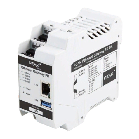
Peak PCAN User manual

CAN FD to LAN Gateway
in DIN Rail Plastic Casing
User Manual
PCAN-Ethernet Gateway FD DR
Document version 1.0.0 (2021-01-13)

PCAN-Ethernet Gateway FD DR – User Manual
2
Relevant Products
Product Name Software Version Part Number
PCAN-Ethernet Gateway FD DR 1.0 IPEH-004012
PCAN® is a registered trademark of PEAK-System Technik GmbH. CANopen® and
CiA® are registered community trademarks of CAN in Automation e.V.
All other product names in this document may be the trademarks or registered trade-
marks of their respective companies. They are not explicitly marked by ™or ®.
Copyright © 2021 PEAK-System Technik GmbH
Duplication (copying, printing, or other forms) and the electronic distribution of this
document is only allowed with explicit permission of PEAK-System Technik GmbH.
PEAK-System Technik GmbH reserves the right to change technical data without
prior announcement. The general business conditions and the regulations of the
license agreement apply. All rights are reserved.
PEAK-System Technik GmbH
Otto-Roehm-Straße 69
64293 Darmstadt
Germany
Phone: +49 (0)6151 8173-20
Fax: +49 (0)6151 8173-29
www.peak-system.com
info@peak-system.com
Document version 1.0.0 (2021-01-13)

PCAN-Ethernet Gateway FD DR – User Manual
3
Contents
1 Introduction 5
1.1 Properties at a Glance 5
1.2 Prerequisites for Operation 6
1.3 Scope of Supply 7
2 Connectors and Operating Elements 8
2.1 CAN1/CAN2 9
2.1.1 Activating the Internal Termination 9
2.2 RS-232 12
2.3 Power Supply 12
2.4 LAN 12
2.5 USB 13
2.6 Reset Button 13
2.7 LEDs 13
3 Putting into Operation 14
3.1 First Connection to the PCAN-Gateway 14
3.1.1 Preparing the Computer 14
3.1.2 Establishing the Connection 15
3.2 Basic Configuration 17
3.2.1 Change Login Data 17
3.2.2 Setting up CAN Channels 17
3.2.3 Connecting to a LAN Network 18
3.3 Installing the PCAN-Gateway 20
4 Operation 22
4.1 Status LEDs 22
4.2 Reboot and Restore 23
4.3 Signal Delay 26

PCAN-Ethernet Gateway FD DR – User Manual
4
5 Configuration 27
5.1 Structure of the Website 28
5.1.1 Header 28
5.1.2 Navigation 28
5.1.3 General Symbols 30
5.2 Status 30
5.3 Routing 32
5.3.1 Manage Routes 33
5.3.2 Add / Edit Route 35
5.3.3 Scan for Devices 39
5.4 Filters 40
5.4.1 Manage Filters 40
5.4.2 Add / Edit Filter 41
5.5 Network 44
5.5.1 CAN 45
5.5.2 LAN 51
5.6 Device 53
5.6.1 Device Configuration 54
5.6.2 User Management 57
5.6.3 Device Monitoring 58
5.6.4 Software Update 59
5.7 Help 61
5.8 Support 61
6 Application Examples 62
6.1 Unidirectional Data Transmission 62
6.2 Bidirectional Data Transmission 64
6.3 Filtering Single CAN IDs 67
7 Technical Specifications 70
Appendix A CE Certificate 73
Appendix B Dimension Drawing 74

PCAN-Ethernet Gateway FD DR – User Manual
5
1 Introduction
The PCAN-Ethernet Gateway FD DR allows access to classic CAN or
modern CAN FD buses via an IP network. On top of that, CAN buses
can be connected to each other via IP using multiple devices. CAN
frames are wrapped in TCP or UDP message packets and then
forwarded via the IP network from one device to another. The
PCAN-Ethernet Gateway FD DR provides a LAN interface and two
CAN FD interfaces that allow bit rates up to 10 Mbit/s. For this, an
AM5716 Sitara processor provides the needed performance.
The PCAN Gateway product family is configured via a convenient
web interface. Alternatively, the JSON interface allows access via
software. Both options provide status information and settings of
the devices, the various communication interfaces, message
forwarding, and filters.
1.1 Properties at a Glance
AM5716 Sitara with Arm®Cortex®M15 core
2 GByte Flash and 1 GByte DDR3 RAM
Linux operating system (version 4.19)
Two High-speed CAN channels (ISO 11898-2)
Comply with CAN specifications 2.0 A/B and FD
CAN FD bit rates for the data field (64 bytes max.)
from 20 kbit/s up to 10 Mbit/s
CAN bit rates from 20 kbit/s up to 1 Mbit/s
Microchip MCP2558FD CAN transceiver

PCAN-Ethernet Gateway FD DR – User Manual
6
Galvanic isolation of the CAN channels up to 500 V against each
other, against RS-232, and the power supply
Connections for CAN, RS-232, and power supply via 4-pole
screw-terminal strips (Phoenix)
LAN interface
Data transmission using TCP or UDP
10/100/1000 Mbit/s bit rate
RJ-45 connector with status LEDs
Monitoring and configuration of the devices via the web
interface or JSON interface
Software update via the web interface
Reboot or reset of the device to a previous software version with
a reset button
Plastic casing (width: 45.2 mm) for mounting on a DIN rail
(DIN EN 60715 TH35)
LEDs for device status and power supply
PCI Express Mini slot, USB port, and a RS-232 connector for
future use
Voltage supply from 8 to 30 V
Operating temperature range from -40 to 70 °C (-40 to 158 °F)
Fan for active cooling when a temperature limit is exceeded
1.2 Prerequisites for Operation
Voltage supply in the range of 8 to 30 V

PCAN-Ethernet Gateway FD DR – User Manual
7
1.3 Scope of Supply
PCAN-Ethernet Gateway FD DR in DIN rail plastic casing
Mating connectors for both CAN channels, RS-232, and power
supply
RJ-45 network patch cord (2 m)
Manual in PDF format

PCAN-Ethernet Gateway FD DR – User Manual
8
2 Connectors and Operating
Elements
Figure 1: Position of the connectors and operating elements (front view)
Figure 2: Position of the connectors (side view)

PCAN-Ethernet Gateway FD DR – User Manual
9
2.1 CAN1/CAN2
The CAN connectors are located on the upper side of the casing.
Figure 3: Pin assignment
CAN connector 1 + 2
Pin Function
1 CAN-High
2 CAN-Low
3 CAN-GND
4 CAN-Shield
The mating connectors (Phoenix Contact MSTB 2,5 / 4-ST BK -
1756298) are included in the scope of supply.
2.1.1 Activating the Internal Termination
A termination of 120 Ohm can be activated for each CAN channel
via solder bridges on the board. A High-speed CAN bus (ISO
11898-2) must be terminated at both cable ends with 120 Ohm each,
otherwise interference will occur. The termination is not activated at
delivery.
Tip: We recommend adding termination at the CAN cabling, for
example with termination adapters (e.g. PCAN-Term). Thus,
CAN nodes can be flexibly connected to the bus.
Do the following to activate the internal CAN termination:
Risk of short circuit! Take great care when soldering to avoid
unwanted short circuits.
Attention! Electrostatic discharge (ESD) can damage or destroy
components on the card. Take precautions to avoid ESD.
1. Disconnect the power supply (Power).

PCAN-Ethernet Gateway FD DR – User Manual
10
2. Use a screwdriver (or something similar) to press lightly
into the notches of the four snap locks on the top and
bottom of the housing.
The snap locks are unlocked.
Figure 4: Housing with the connection front on the right side
3. Pull the two casing sections apart.
Figure 5: Open housing with the back of the board
to activate the internal termination
4. Set the solder bridge(s) on the circuit board according to the
desired settings
Figure 6 shows the position of the solder fields.

PCAN-Ethernet Gateway FD DR – User Manual
11
The following table contains the possible settings.
Figure 6: Bottom side of the power board with the solder fields
to activate the internal termination
Internal Termination
Connector Soldering Fields Without
(standard)
Active
CAN 1 JP1 and JP2
CAN 2 JP3 and JP4
5. Re-insert the circuit board into the guide slot of the
counterpart of the housing and push both parts together
until the snap locks engage with a clicking sound.

PCAN-Ethernet Gateway FD DR – User Manual
12
2.2 RS-232
The RS-232 connector is located on the lower side of the casing.
Figure 7: Pin assignment
RS-232 connector
Pin Function
1 GND
2 RxD
3 not connected
4 TxD
The mating connector (Phoenix Contact MSTB 2,5 / 4-ST BK -
1756298) is included in the scope of supply.
2.3 Power Supply
The connection for the power supply is located on the lower side of
the casing.
Figure 8: Pin assignment
Power connector
Pin Function
1 GND
2 not connected
3 Vbat (8 - 30 V)
4 Shield (top hat rail potential)
The mating connector (Phoenix Contact MSTB 2,5 / 4-ST BK -
1756298) is included in the scope of supply.
2.4 LAN
The RJ-45 connector for connecting to a LAN network is centered on
the front of the casing.

PCAN-Ethernet Gateway FD DR – User Manual
13
Figure 9: Pin assignment
RJ-45 connector
Pin Function
1 TxD
2 TxD
3 RxD
4 not connected
5 not connected
6 RxD
7 not connected
8 not connected
2.5 USB
The USB downstream port is used to connect additional USB
devices to the PCAN-Ethernet Gateway FD DR.
Figure 10: USB port
2.6 Reset Button
The PCAN-Ethernet Gateway FD DR can be restarted or reset with
the Reset button. You can find more information in chapter 4.2
Reboot and Restore
on page 23.
2.7 LEDs
The PCAN-Ethernet Gateway FD DR has LEDs for the device status
and power supply, two LAN LEDs, and LED 1 to 3. For more
information, see section 4.1
Status LEDs
on page 22.

PCAN-Ethernet Gateway FD DR – User Manual
14
3 Putting into Operation
The PCAN-Ethernet Gateway FD DR is configured via a web
interface. Therefore, the module must be connected via LAN to a
computer, located in the same logical network as your gateway
(192.168.1.xxx).
3.1 First Connection to the PCAN-Gateway
During initial operation or after resetting to factory defaults, you
must pre-configure the PCAN-Gateway for your LAN. The default
login data is written on the label on the left side of the PCAN-
Gateway. Proceed as described in the following subsections:
3.1.1 Preparing the Computer
Your computer must be configured with an appropriate IP address
to connect to the device via LAN.
Do the following to determine your IP address:
1. Open the Windows Start menu.
2. Type ncpa.cpl and press Enter.
The overview of the network adapters appears.
3. Do a right-click on the adapter that will be used for the
connection to the PCAN-Gateway and select Properties.
4. Open the properties of Internet Protocol Version 4
(TCP/IPv4).

PCAN-Ethernet Gateway FD DR – User Manual
15
Do the following to change your IP address:
1. Make a note of the current settings in order to reset the
computer later on.
2. Select Use the following IP address.
3. Enter an IP address in the range from 192.168.1.1 to
192.168.1.254 (but not the PCAN-Gateway's own address
which is indicated on the left casing side).
4. Click on Subnet mask. 255.255.255.0 is shown. Leave this
entry unchanged.
5. Confirm the entries with OK.
3.1.2 Establishing the Connection
Do the following to establish a connection:
1. Connect the RJ-45 connector of the PCAN-Gateway via a
LAN cable (included in the scope of supply) directly to the
computer.
2. Connect the device to a suitable power supply (8 - 30 V).
3. Wait until the PCAN-Gateway is ready (Status LED is
blinking green).
4. Open a web browser on the computer.
5. In the browser's address bar, enter the address of the PCAN-
Gateway (see the label on the left side of the device).

PCAN-Ethernet Gateway FD DR – User Manual
16
Figure 11: IP and access information on the left side of the device
Figure 12: Address bar of the web browser
This opens the configuration website.
6. In the upper right area of the configuration website you can
find the login.
7. Enter “admin“ for each the username and the password and
confirm with Enter.
The restricted area appears and you can start setting up the
PCAN-Ethernet Gateway FD DR. You can find a description
of the basic configurations in the following section 3.2.
Note: Afterwards, reset the computers IP address to the
previously noted address.

PCAN-Ethernet Gateway FD DR – User Manual
17
3.2 Basic Configuration
Change your login data first and then set up the PCAN-Gateway
connection to CAN and the LAN network.
3.2.1 Change Login Data
1. Open the page Device > User Management.
2. Change the login data on this page. Create a new username
and a new password.
To ensure a minimum level of security, the password should
have at least 8 characters. If possible, use letters, numbers,
and special characters.
Important notice: Login data is confidential! Do not act care-
lessly and leave your system open to attack. Never deposit the
login data in any form on the Internet or make it easily
accessible. Do not give the new login data carelessly to third
parties nor send it by e-mail.
3.2.2 Setting up CAN Channels
Do the following to configure the CAN channels:
1. Open the page Network > CAN.
2. Nominal Bit Rate: For setting the nominal bit rate, click the
drop-down menu and select the value that is used on the
CAN bus to be connected.
3. CAN FD: If the CAN bus to be connected uses the new
standard CAN FD, activate the checkbox CAN FD. The form
for selecting the data bit rate appears.
4. Data Bit Rate: For setting the data bit rate, click the drop-
down menu and select the value that is used on the CAN
bus to be connected.

PCAN-Ethernet Gateway FD DR – User Manual
18
5. ListenOnlyMode: If the PCAN-Gateway should act as a
pure observer, not affecting the data traffic, Listen-Only-
Mode must be enabled. Activate Listen-Only-Mode with a
click on the checkbox.
6. Confirm the entries with Save Settings.
3.2.3 Connecting to a LAN Network
Do the following to configure the IP address data of the PCAN-
Gateway for the LAN network to be connected:
Manual Address Assignment (Recommended)
1. Open the page Network > LAN.
2. If automatic address assignment via DHCP is not used, enter
the IP address and Subnet mask that the PCAN-Gateway
should use in the LAN network at the bottom of the page.
The gateway address can optionally be set.
3. Confirm the entered data with Save Settings.
You are automatically forwarded to the new IP address. The
basic setup of the device is now completed.
Automatic Address Assignment via DHCP
Note: DHCP is not recommended, because it is necessary to
know the IP address of the device to access the configuration
website. Furthermore, the IP address may change after a restart
of the device or the DHCP server. In this case the existing
routes won't work.
1. Open the page Network > LAN.
2. If the future LAN network uses DHCP (Dynamic Host
Configuration Protocol), the PCAN-Gateway IP address and

PCAN-Ethernet Gateway FD DR – User Manual
19
Subnet mask are assigned automatically. Enable DHCP to
use this feature.
3. Confirm the entered data with Save Settings.
You are automatically logged out and the basic setup of the
device is now completed. When the PCAN-Gateway is
installed in the LAN, it automatically receives its new
address data via DHCP.

PCAN-Ethernet Gateway FD DR – User Manual
20
3.3 Installing the PCAN-Gateway
Do the following to connect the device to an IP network
(Ethernet):
1. Mount the PCAN-Ethernet Gateway FD DR at the
appropriate position on the DIN rail by placing it at the top
of the rail and snapping it to the bottom.
Note: Please consider the recommended installation
distances to ensure a suitable air flow for cooling. When a
temperature limit is exceeded, the device is actively cooled
with a fan.
Figure 13: Recommended installation distances
This manual suits for next models
1
Table of contents
Other Peak Gateway manuals
Popular Gateway manuals by other brands

AudioCodes
AudioCodes Mediant 2000 installation guide

National Instruments
National Instruments 9792 Getting started guide

Aztech
Aztech VDSL5040GRV(AC) user manual

Softing
Softing epGate PA user guide

Salto
Salto GATEWAYx1 installation guide

Tadiran Telecom
Tadiran Telecom TGW4 SERIES User configuration manual