Pearson P31-II User manual

1
1
November 22, 2002
For P31 owners who do not have the original owners manual, I felt that it was worthwhile to offer a copy of the on
that came with my 1991 P31-II #268. The dates on the pages and drawings imply that the manual was changed little
from 1998 on and is therefore applicable.
It also appears that Pearson used the same text for most of their manuals and inserted appropriate drawings for the
specific model being shipped. The general information should be useful to all Pearson owners.
The final page contains Keel Bolt torque values for Pearson Models 27 through P39
I used OCR (Optical Character Recognition) software to read the manual and convert it into Word 6.0. This allowed
me to keep the size of the file as low as possible for downloading. The pages that have drawings on them were
scanned as .bmp bit maps. These were inserted into the word document.
Bill Crane
P31-II Talaria

2
2
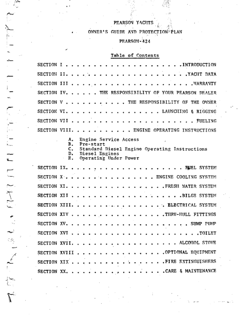
TABLE OF CONTENTS
QUICK REFERENCE LOCATION SHEET
INTRODUCTION SECTION 1
INTRODUCTION 1.1
FORMAT 1.2
WARRANTY 1.3
OWNER RESPONSIBILITY 1.4
COMMISSIONING SECTION 2
INTRODUCTION 2.1
PRE-LAUNCH CHECKS 2.2
Hull Inspection 2.2.1
Machinery Inspection 2.2.2
Before Mast Is Stepped 2.2.3
Equipment On Board 2.2.4
POST-LAUNCH CHECKS 2.3
Hull Inspection 2.3.1
Electrical Inspection 2.3.2
Machinery Inspection 2.3.3
Rigging and Sails 2.3.4
Fresh Water System 2.3.5
Head System 2.3.6
Galley 2.3.7
OWNER RESPONSIBILITY 2.4
Mandatory Coast Guard Equipment 2.4.1
Recommended Safety Equipment 2.4.2
Ground Tackle 2.4.2.1

3
3
Medical Kit 2.4.2.2
Tool Kit 2.4.2.3
Spare Parts 2.4.2.4
Additional Safety Equipment 2.4.3
Dealer Responsibility 2.4.4
YACHT SYSTEMS - SPARS AND RIGGING SECTION 3
MAST 3.1
Masthead Assembly 3.1.2
Spreaders and Standing Rigging 3.1.3
BOOM 3.2
Continuou3 Line Reefing (internal ) 3.2.1
DOCKSIDE TUNING 3.3
Before Mast is Stepped 3.3.1
While Stepping Mast 3.3.2
After Stepping Mast 3.3.3
Rake Adjustment 3.3.3.1
Side-to-Side Perpendicularity 3.3.3.2
UNDERWAY TUNING 3.4
Weather Helm 3.4.1
CARE AND MAINTENANCE 3.5
Rigging and Lines 3.5.1
Winches 3.5.2
YACHT SYSTEMS - POWER SECTION 4
GENERAL DESCRIPTION 4.1
DIESEL - OPERATION 4.2
Additional Controls 4.2.1

4
4
Before Starting 4.2.2
Starting 4.2.3
Stopping 4.2.4
DIESEL - MAINTENANCE 4.3
Fuel Sanitation 4.3.1
Bacterial Contamination 4.3.2
Fuel Additives 4.3.3
FUEL SYSTEM - GENERAL DESCRIPTION 4.4
FUEL SYSTEM - FUELING 4.5
Before Fueling 4.5.1
Fueling Procedures 4.5.2
After Fueling 4.5.3
Oil Pan & Caution 4.5.4
PROPELLER AND SHAFT ASSEMBLY 4.6
Shaft Packing Gland 4.6.1
Adjustment 4.6.1.1
Shaft Coupling 4.6.2
Flex Coupling 4.6.2.1
To Disconnect Coupling 4.6.2.2
To Check Alignment 4.6.2.3
To Reconnect Coupling 4.6.2. 4
YACHT SYSTEMS - SECTION 5
GENERAL DESCRIPTION 5.1
Messenger Lines 5.1.1
BATTERY 5.2
Electrolyte Level 5.2.1
Discharged State 5.2.2
Clear Connections 5.2.3

5
5
LIGHTNING PROTECTION & BONDING SYSTEMS 5.3
Bonding System 5.3.1
Lightning Protection System 5.3.2
UNDERWATER GALVANIC CORROSION 5.4
Electrolysis 5.4.1
Checklist 5.4.2
Propeller and Shaft 5.5.1
Electrical Switches 5.5.2
External Factors 5.5.3
YACHT SYSTEMS – STEERING SECTION 6
GENERAL DESCRIPTION 6.1
Wheel Steering System 6.1.1
Emergency Tiller 6.1.2
YACHT SYSTEMS – HULL SECTION 7
THRU-HULL FITTINGS 7.1
FRESH WATER SYSTEM 7.2
Hot/Cold Pressure Water System 7.2.1
Water System Maintenance 7.2.2
PROPANE SYSTEM 7.3
Operation 7.3.1
General 7.3.2
Head and Waste System 7.4
MAINTENANCE SUMMARY SECTION 8
INTRODUCTION 8.1
ROUTINE MAINTENANCE 8.2

6
6
Topsides, Decks and Below Decks 8.2.1
Gelcoat 8.2.1.1
Wood Surfaces 8.2.1.2
Window Maintenance 8.2.1.3
Below The Waterline 8.2.2
Bottom Cleaning 8.2.2.1
Bottom Preparation 8.2.2.2
Bottom Painting 8.2.2.3
Winches 8.2.3
Spars And Rigging 8.2.4
Cleaning Wire Rope and Rigging 8.2.4.1
Cleaning Synthetic Rope 8.2.4.2
Rigging Inspection 8.2.4.3
Engine System 8.2.5
Electrical System 8.2.6
Steering System 8.2.7
LAYING UP 8.3
Before Hauling 8.3.1
After Hauling 8.3.2
FITTING OUT 8.4

7
7
LIST OF ILLUSTRATIONS
TITLE FIGURE NUMBER
MASTHEAD ASSEMBLY 3.1.1
TYPICAL SPREADER INSTALLATION 3.1.2
RIGGING SCHEMATIC 3.1.3
CONTINUOUS LINE REEFING 3.2.1
MAST INSTALLATION 3.3.1
TIE ROD INSTALLATION 3.3.2
POWER SYSTEM SCHEMATIC 4.2
SHAFT ALIGNMENT 4.6
120 VOLT DC ELECTRICAL DIAGRAM 5.1
ELECTRICAL PANEL 5.2
BONDING SYSTEM 5.3
MAST AND INSTRUMENT WIRES 5.4
TRANSDUCER WIRE LEADS 5.4.1
EMERGENCY TILLER INSTALLATION 6.1
THRU-HULL LOCATION SCHEMATIC 7.1
FRESH WATER SYSTEM 7.2
TANK LOCATIONS 7.2.1
PROPANE SYSTEM SCHEMATIC 7.3
Y-VALVE, HOLDING TANK 7.4

8
8
For your convenience the following list of important
locations on your Pearson has been included.
QUICK REFERENCE LOCATION SHEET
EMERGENCY TILLER IN SAIL LOCKER
HEAD INTAKE VALVE BELOW TRAP AT FWD END OF THE
STBD SETTEE
HEAD OVERBOARD DISCHARGE BELOW VANITY
VALVE
DISCHARGE SELECT VALVE BELOW VANITY
HOLDING TANK (24 gal.) BELOW V-BERTH
ENGINE RAW WATER INTAKE VALVE BELOW BUNK TRAP AFT OF ENGINE
BOX, STBD SIDE
ENGINE RAW WATER STRAINER BELOW ENGINE BOX FWD OF THE
VALVE ENGINE
PROP SHAFT PACKING NUT BELOW BUNK TRAP AFT OF ENGINE
BOX ON CENTERLINE
ENGINE OIL DIP STICK STBD SIDE OF ENGINE ACCESS
PANEL ON STBD SIDE OF ENGINE
BOX
TRANSMISSION OIL DIPSTICK ON TRANSMISSION ACCESS BELOW
TRAP AFT OF ENGINE BOX ON
QUARTERBERTH TOP
OVERFLOW RESERVOIR BOTTLE STBD SIDE OF ENGINE BELOW
ENGINE BOX COVER
FUEL TANK BELOW QUARTERBERTH BUNK TOP
AFT END
FUEL GAUGE ON FUEL TANK BELOW CUSHION
FUEL FILTER BELOW BUNK TRAP AFT OF ENGINE
BOX, STBD SIDE
FUEL “SHUT OFF” VALVE ON FUEL FILTER
PROPANE TANK PROPANE BIN, AFT END OF
COCKPIT, PORT SIDE
PROPANE SOLENOID PROPANE BIN
PROPANE SWITCH ON ELECTRICAL PANEL AT NAV
STATION ABOVE ICEBOX

9
9
BATTERIES BELOW QUARTERBERTH, FWD END
BATTERY SELECT SWITCH QUARTERBERTH FRONT BETWEEN
ENGINE BOX AND BUREAU
DC ELECTRICAL PANEL ABOVE ICEBOX AT NAV STATION
AC ELECTRICAL PANEL ABOVE ICEBOX AT NAV STATION
SUMP PUMP BELOW VANITY
SUMP PUMP SWITCH HEAD LOCKER, FWD END
SUMP DISCHARGE VALVE BELOW PORT SETTEE, FWD END
PORT WATER TANK (20 gal.) BELOW PORT SETTEE, AFT END
STBD WATER TANK (20 gal.) BELOW STBD SETTEE, AFT END
PORT TANK "SHUT OFF" VALVE BELOW GALLEY SINK, PORT SIDE
STBD TANK "SHUT OFF" VALVE BELOW GALLEY SINK, STBD SIDE
FRESH WATER FILTER BELOW GALLEY SINK ON PRESSURE
WATER MANIFOLD
FRESH WATER PRESSURE PUMP BELOW GALLEY SINK
GALLEY SINK DRAIN BELOW GALLEY SINK
VANITY SINK DRAIN BELOW SETTEE, FWD END
ANCHOR LOCKER DRAIN ON BOW STEM
DECK DRAIN (PORT) SAIL LOCKER, FWD END
DECK DRAIN (STBD) LAZARETTE AREA, AFT OF
QUARTERBERTH BEHIND ACCESS
PANEL, STBD SIDE
COCKPIT DRAINS LAZARETTE AREA, AFT OF
QUARTERBERTH BEHIND ACCESS
PANEL, STBD SIDE
PROPANE BIN DRAIN LAZARETTE AREA, AFT OF
SAIL LOCKER BEHIND ACCESS
PANEL, STBD SIDE
ICEBOX DRAIN PUMP AT SINK, ACCESS DRAIN
FITTINGS BELOW ICEBOX
WATER FILL (PORT TANK) PORT SIDE DECK, MIDSHIP
WATER FILL (STBD TANK) STBD SIDE DECK, MIDSHIP
FUEL FILL COCKPIT COAMING, AFT PORT
END

10
10
WASTE PUMP OUT ANCHOR LOCKER, BOTTOM
WATER TANK VENT (PORT) AFT END OF PORT SETTEE ON
BULKHEAD
WATER TANK VENT (STBD) AFT END OF STBD SETTEE ON
BULKHEAD
FUEL TANK VENT ON TRANSOM, UPPPER PORT
CORNER
HOLDING TANK VENT BELOW SHEER ON STBD HULL
SIDE ADJACENT TO HEAD AREA
PROPANE BIN VENT ON TRANSOM, UPPER STBD
CORNER
BILGE PUMP PORT COCKPIT COAMING
BILGE PUMP PICKUP B ELOW DUST BIN
BILGE PUMP DISCHARGE ON TRANSOM, LOWER STBD
CORNER

11
11
INTRODUCTION
SECTION 1
1.1 INTRODUCTION
1.1
This manual is intended to acquaint you with the
various features of your Pearson yacht and to provide
information related to the care and upkeep of the
yacht and its equipment. The manual supplements the
literature supplied by the manufacturers of the
systems and equipment installed in the yacht, and
wherever practicable refers to this literature. It is
recommended that the literature supplied by
manufacturers be retained and the instructions therein
followed.
1.2 FORMAT
The manual is divided into four basic sections.
Section 1, this section, contains a brief description
of the contents, format of the manual, and the
warranty. The warranty information included on the
following page should be read carefully. This
information, along with the warranty and parts
information supplied by manufacturers of the system
installed, will help maintain the yacht and all of it~
systems.
Section 2 of the manual covers the procedures that
should be followed when commissioning the yacht. It
includes the procedures that should be followed by the
dealer at time of commissioning, as well as those
items (such as safety equipment) that are the owner's
responsibility. This section of the manual should
also prove useful in subsequent recommissionings after
periods of layup.
Section 3, ~, 5, 6, and 7 of the manual describes the
various systems used on the yacht. Reference is made
to manufacturers' instructions such as the engine
manual and additional information is supplied whenever
installations vary from the general conditions assumed
in the manufacturers' instructions.
Section 8 provides a maintenance summary covering the
procedures that should be followed to maintain the
beauty and serviceability of the yacht. There are
three sections: routine maintenance, laying-up
procedures, and fitting-out procedures. Whenever
feasible, reference is made to the appropriate
manufacturer's literature.

12
12
1.3 WARRANTY
PEARSON YACHTS are carefully inspected and tested
prior to shipment from our factory.
Because of this attention to quality control, our
warranty is one of the most effective in the industry.
More important, however, is the knowledge and
cooperation you as the owner, and we as the
manufacturer, receive from the PEARSON Dealer
Organization.
Your warranty is included in your file of ship’s
papers. Be sure to follow the instructions on filling
out and forwarding. you can rest assured that our
policy towards your warranty will result in your
satisfaction.
IMPORTANT NOTICEI
UNDER NO CIRCUMSTANCES WILL PEARSON YACHTS WARRANTY A
HYDRAULIC ADJUSTER PURCHASED FROM A SOURCE OTHER THAN
PEARSON YACHTS. IF THE ADJUSTER IS INSTALLED BY
PEARSON DURING THE CONSTRUCTION OF THE YACHT, A
WARRANTY COVERING THE INSTALLATION WILL BE SUPPLIED BY
PEARSON. SHOULD THE ADJUSTER BE PURCHASED ON A PARTS
ORDER AND BE DEALER INSTALLED, THE DEALER WILL
GUARANTEE THE INSTALLATION. THE ADJUSTER ITSELF
CARRIES ITS OWN MANUFACTURER’S WARRANTY.

13
13
1.4 RESPONSIBILITY OF THE OWNER
1. Your prompt return of the warranty will help us ensure
continued satisfaction. Your dealer will provide you
with the required information and will co-sign the
warranty. Please return the manufacturerts copy
within thirty (30) days after taking delivery of your
new boat.
2. Thoroughly check your Ship1s Papers file to ensure
that all instructions furnished with accessories are
included.
3. Your Pearson dealer will competently handle any
service problems that may arise. It is essential that
you contact him for all warranty matters.
4. When it is necessary to contact Pearson, please
address your letters as follows indicating your boat
and hull number:
PEARSON YACHTS
WEST SHORE ROAD
PORTSMOUTH, RI 02871
Attn: Customer Service Department

14
14
COMMISSIONING
SECTION 2
2.1 INTRODUCTJON
2.1.1 The first commissioning of a yacht is essentially the start
of the yacht's life, and the importance of proper
commissioning procedures at this time cannot be
overestimated. The commissioning procedure will be
performed by dealer personnel and requires no owner
participation. Therefore, the owner need only to concern
himself with items such as safety equipment which is
considered to be his responsibility. Items of owner
responsibility are further delineated in paragraph 2.4 of
this section.
2.1.2 Complete lists of the pre-launch and post-launch checks
employed during commissioning are provided in this section
for those owners interested in understanding the
decommissioning procedure, as well as for future use in any
recommissionings that may be required after periods of wet
or dry storage. The lists assume performance by persons
cognizant of the procedures that are required, and do not
attempt to provide step-by-step instructions. Detailed
procedures are available in section 3 of this manual and
other manufacturers' instructions that are provided with
the yacht.
2.1.3 The factory installed equipment, and items of owner
responsibility that require attention during commissioning
are included in the list with the items marked with an
asterisk (~), and the items involving owner responsibility
marked with a double asterisk (11*).
2.2PRE-LAUNCH CHECKS
2.2.1Hull Inspection.
Check topsides, decks, and all interior spaces for
cleanliness and proper finish. Make certain that all
foreign matter has been removed from the bilge areas,
and check the following specific items:
____ All thru-hull valves lubricated and closed, all hose
clamps tight.
Propeller nuts and cotter pin properly made up.
Steering gear and rudder operational.
____ Strut bearing in place and secured.
* * Anti-fouling bottom paint applied.

15
15
2.2.2 Machinery Inspection.
Make an overall inspection of the machinery spaces.
Ensure that they are free of loose material that might
interfere with machinery operation, and then check the
following items:
Engine installation work completed.
Engine oil, transmission fluid, and coolant levels
sat isfatory.
____ All electrical switches OFF.
____ Batteries fully charged, tied down, connected;
electrolyte at proper level.
* Installation of all equipment completed.
____ All fuel and *LPG valves CLOSED.
Adequate amount of fuel in tank.
2.2.3 Before Mast is Stepped.
WARNING!! MOVE YOUR BOAT TO A POSITION THAT IS CLEAR
OF OVERHEAD WIRES OR OBSTRUCTIONS. ELECTROCUTION MAY
RESULT FROM CONTACT WITH ANY OVERHEAD WIRES! I
Check the following items:
Shrouds, stays, spreaders, installed and properly
secured to mast. Check wire rigging for kinks or
defects.
* Masthead lights, spreader lights, and mast-mounted
instrument units operational.
* VHF antenna installed.
____ All chafe points on mast properly taped.
2.2.4 Equipment On Board.
Check the following items:
____ Winch handles, emergency tiller, and bilge pump
handles.
Ground tackle.
Dock lines and fenders.
**
**

16
16
** Safety equipment:
pfd's (life preservers)
throwable horseshoe or ring buoy
horn
ship1s bell
emergency signals (flares, etc.)
fire extinguishers.
Medical kit.
** Spare parts and tool kit.
2.3 POST-LAUNCH CHECKS.
2.3.1 Hull Inspection.
Make an overall inspection of the hull interior.
Check bilge areas for evidence of major leaks near
thru-hulls, and then make the following specific
checks:
Open all thru-hull seacocks. Check each valve and
associated hoses, couplings, etc.
____ Check propeller shaft packing gland for nominal
adjustment. Unless major leaking is observed, defer
adjustment until paragraph 2.3.3.
____ After the boat is rigged check shaft alignment, align
if necessary, connect couplings. (See Fig. 4 .~)
2.3.2 Electrical Inspection.
Make the following checks:
____ Check the 12 volt supply at the electrical panel with
the battery switch in the #1, #2, and ALL positions.
____ Make an operational check of all DC circuits connected
to the electrical panel.
____ Connect the shore power cable, check the polarity
indicator, close the main breaker, and make an
operational check of the following items if installed.
120 volt receptacles
Hot water heater
Converter
Other AC equipment

17
17
2.3.3 Machinery Inspection.
____ Secure the yacht to a pier or dock with bow, stern,
and spring lines and operate the engine at low speeds
in neutral, forward, and reverse. Check:
throttle and shift controls
engine operation
charging current
water temperature See engine owner1s manual for
operating temperature range.
oil pressure (see engine manual).
____ Check the fuel system for leakage.
____ Recheck the shaft packing gland for proper adjustment.
Adjust if necessary. (See Paragraph 4.6.1)
____ Install and check the operation of the emergency
tiller.
2.3.4 Rigging And Sails.
Check the following after mast is in place:
____ All standing rigging complete and in place, dockside
tuning completed. (See paragraph 3.3)
____ All cotter pins in place and taped.
Running rigging in place.
____ Sails hoisted to check fit.
2.3.5 Fresh Water System.
Check the following:
____ Water tanks full, no leaks at tank or fittings.
* Pressure water system operational.
____ Sinks and drains operational.
~ Hot water system operational.
* Shower operational.
* Sump pump operational.
Bilge pump operational.

18
18
2.3.6 Head System.
Check the following:
Head, holding tank, or other Marine Sanitation Devices
operational.
____ Head intake and discharge hoses for leaks.
____ Y-valve and discharge plumbing.
2.3.7 Galley.
Check the following:
Propane valve, tank, and gauge functioning properly.
(See Fig. 7.3)
Galley stove operational.
2.4 OWNER RESPONSIBILITIES.
For maximum enjoyment of your Pearson, due regard must
be given to proper safety and maintenance procedures.
The following is a partial list of items that are the
responsibility of the owner:
Insure that your boat is operated according to the
U.S. Coast Guard Regulations as outlined in the
'1Federal Requirements For Recreational Boats'1. A copy
of this pamphlet is included in your owner's manual
and you should familiarize yourself with all operating
requirements.
Prepare yourself for any situation before going out on
the water. Follow the instructions provided in the
sections of this owner's manual, the individual
supplier instruction manuals, and all applicable U.S
Coast Guard and other regulations.
If you are not an experienced sailor, you should
attend an accredited sailing school.
Before leaving the dock: be sure that all your
equipment is in working order, that you are aware of
the weather conditions, and that someone ashore is
familiar with your destination or float plan.
2.4.1 Mandatory Coast Guard Safety Equipment.
Many safety items are required for compliance with the
U.S. Coast Guard regulations. Note that these
regulations are subject to change. It is the owner's
responsibility to be cognizant of current regulations
as outlined in the "Federal Requirements for

19
19
Recreational Boats". Additional copies may be
obtained by writing the Consumer Affairs Staff, U.S.
Coast Guard Headquarters, Washington, D.C. 20953 or by
calling 2O2-~72-23814.
Depending on the length, passenger capacity, and
operating conditions, your boat must be equipped
according to the current U.S.C.G. regulations. Be
sure that you operate your boat with the necessary
PFDs (life preservers), fire extinguishers, signaling
devices, distress signals, navigation lights, etc. as
referred to in the '1Federal Requirements for
Recreational Boats".
2.4.2 Recommended Safety Equipment.
Preparation is the key to safety on the water. As a
minimum guide, we recommend that you outfit your boat
with the following equipment:
a compass - that is properly adjusted to give the
correct magnetic reading.
a large capacity bilge pump
updated nautical charts of your intended cruising area
boat hook
large waterproof flashlight with spare batteries.
3 fenders
docking lines - a good rule of thumb to follow
dictates that your bow, stern, and spring be equal to
the length of the boat. We recommend 1/2 inch dacron
line for this purpose.
2.4.2.1 Ground Tackle
Anchor and rode - the following suggestions are
provided as a general guide and should be revised to
suit the the areas in which the yacht is to be sailed
and the personal preference of the owner:
TYPE ANCHQ~~ C:HATN RODF
5H Lunch 61 x i/~" 150' x 3/8"
12H Working BBB GALV. 3 STRAND
20H Storm PROOF COIL NYLON LINE
DANFORTH*
DANFORTH ANCHORS are manufactured exclusively by
Danforth, Div. of Eastern Co., 500 Riverside
Industrial Parkway, Portland, Maine, 0Li103

20
20
2.4.2.2 medical kit - Every yacht should carry a first aid
manual, and a medical kit tailored to the specific
needs and capabilities of the owner. Any ship1s store
should carry a standard type medical kit. Items in
the kit should include:
aspirin
over-the-counter motion sickness pills
adhesive strips and tape
ammonia inhalants
antiseptic wipes
antiseptic germicide ointment
sunscreen first aid/burn cream
zinc oxide ointment
gauze bandages
insect/bee sting relief wipes
sterile pads
cold packs for sprains
scissors
tweezers
2.4.2.3 tool kit - a basic kit should consist of:
wrenches - adjustable, open end, box, socket
hammers - large and small
knife - with~marlinspike
screwdrivers - large and small, standard and Phillips
pliers - regular, cutting and needle nose, vise grips
wire cutter - capable of cutting standing rigging
hacksaw - with spare blades
2.4.2.4 spare parts - a basic kit should consist of:
standing rigging repair materials such as cotter pins,
tumbuckles, stainless wire, clevis pins
running rigging and sail repair material such as
blocks, extra line, sail slides, duct tape.
assortment of stainless steel screws, nuts, bolts, and
washers
hose clamps
electrical tape, wire, crimp on lugs
spare navigation light bulbs
lubricating supplies - WD-~O, silicone grease
check engine manual for spare parts, engine oil and
transmission fluid recommendations
sail repair kit
chafe tape - white vinyl
2.4.3 Additional Safety Equipment.
A number of additional safety items are worthy of
consideration. These range from safety harnesses to
emergency beacons, life rafts, and survival suits.
Their use depends upon the intended use of the yacht.
We suggest you investigate the necessity of these
items through discussion with your dealer.
Table of contents
Other Pearson Boat manuals