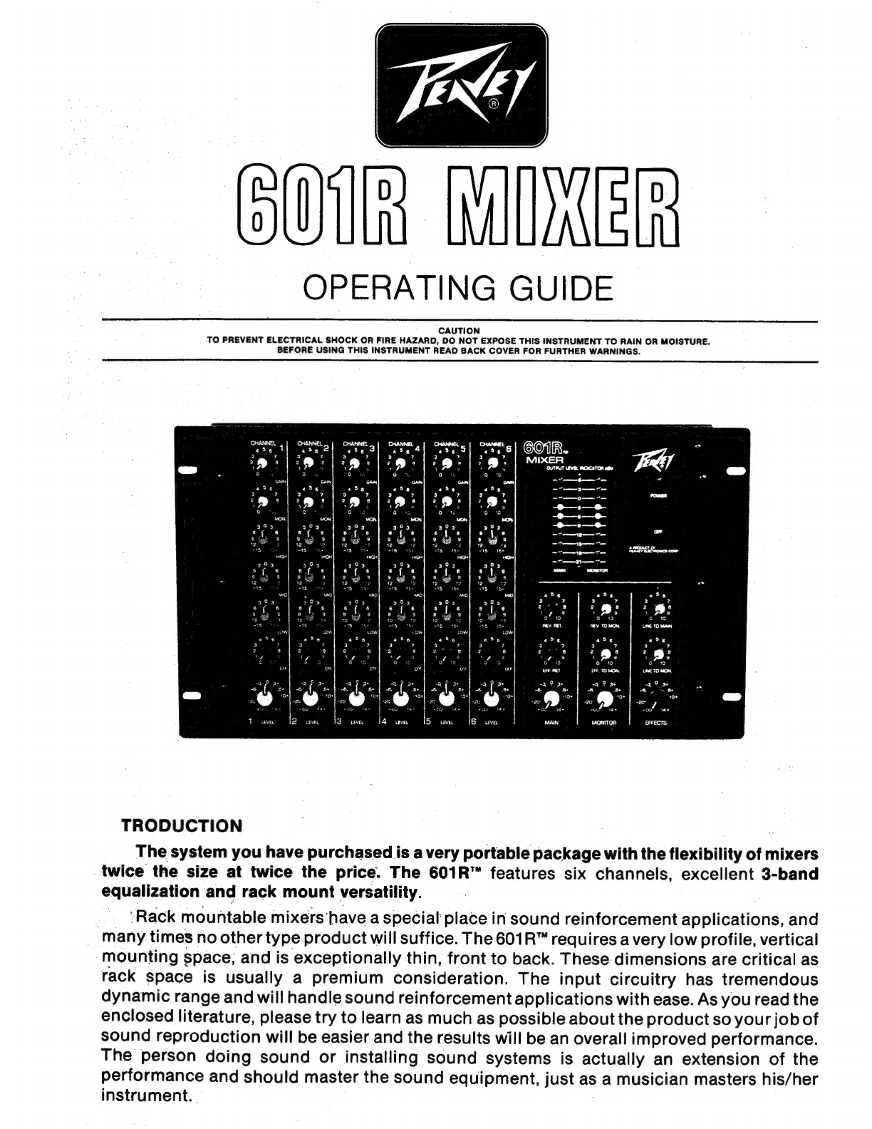
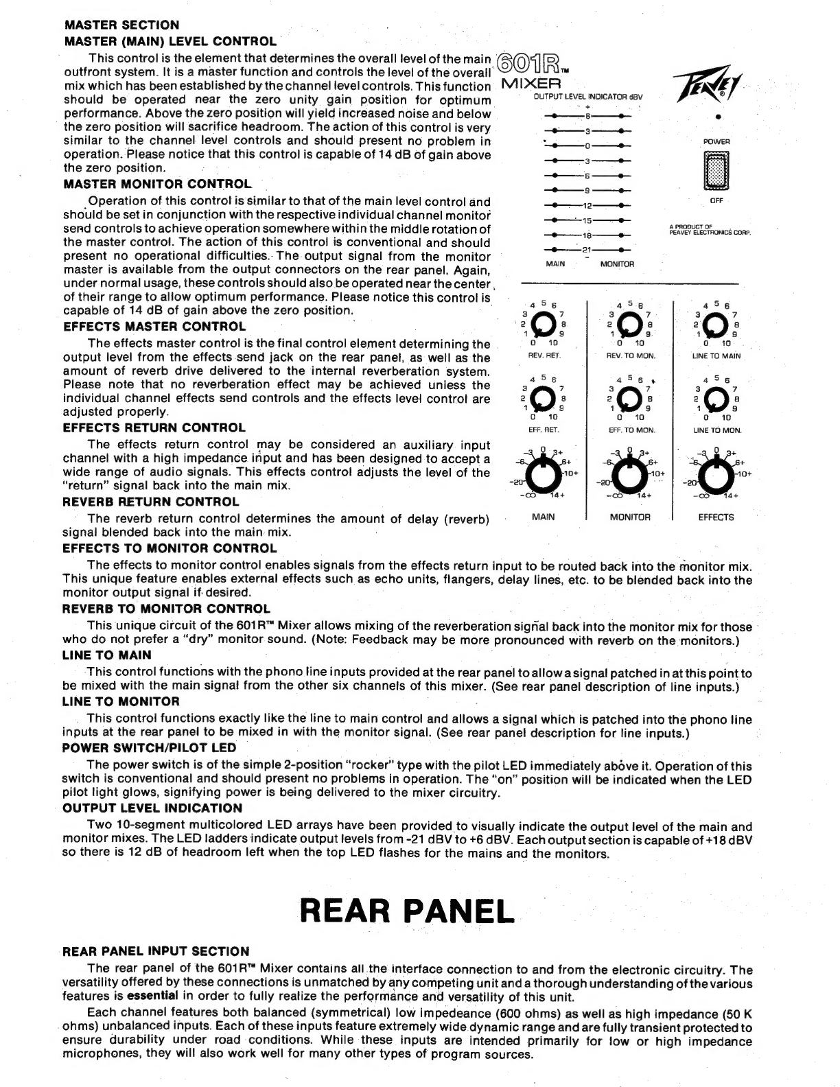
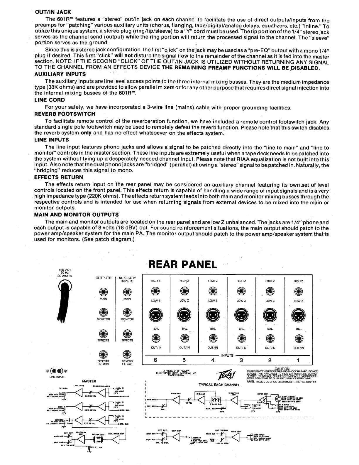
Peavey 601R User manual

OUI
MIKER
OPERATING
GUIDE
CAUTION
TO
PREVENT
ELECTRICAL
SHOCK
OR
FIRE
HAZARD,
DO
NOT
EXPOSE
THIS
INSTRUMENT
TO
RAIN
OR
MOISTURE.
BEFORE
USING
THIS
INSTRUMENT
READ
BACK
COVER
FOR
FURTHER
WARNINGS.
4562
EE
6C1R.
.
?
3
'|».-
TRODUCTION
The
system
you
have
purchased
is
a
very
portable
package
with
the
flexibility
of
mixers
twice
the
size
at
twice
the
price.
The
601R™
features
six
channels,
excellent
3-band
equalization
and
rack
mount
versatility.
...
:Rack
mountable
mixers
have
a
special
place
in
sound
reinforcement
applications,
and
many
times
no
other
type
product
will
suffice.
The
601R™
requires
a
very
low
profile,
vertical
mounting
space,
and
is
exceptionally
thin,
front
to
back.
These
dimensions
are
critical
as
rack
space
is
usually
a
premium
consideration.
The
input
circuitry
has
tremendous
dynamic
range
and
will
handle
sound
reinforcement
applications
with
ease.
As
you
read
the
enclosed
literature,
please
try
to
learn
as
much
as
possible
about
the
product
so
your
job
of
sound
reproduction
will
be
easier
and
the
results
will
be
an
overall
improved
performance.
The
person
doing
sound
or
installing
sound
systems
is
actually
an
extension
of
the
performance
and
should
master
the
sound
equipment,
just
as
a
musician
masters
his/her
instrument.
|

INPUT
GAIN
CONTROL
The
input
gain
control
determines
the
sensitivity
of
each
individual
channel.
It
should
be
adjusted
accordingly
to
each
instrument
or
vocal
that
is
being
patched
into
this
system.
The
operator
must
adjust
the
input
gain
so
that
overload
“clipping”
is
avoided
at
the
input.
A
very
strong
signal
coming
into
the
mixer
would
require
a
fairly
low
setting
of
the
input
gain:control,
and
obviously,
a
very
weak
signal
will
require
a
fairly
high
setting
of
this
control.
Proper
adjustment
of
the
input
gain
control
may
be
easily
E
by
setting
up
the
highest
expected
input
signal
level
and
adjusting
the
input
gain
so
that
o
"clipping"
or
distortion
is
heard
from
the'amp/speaker
system.
After
this
mixer
has
been
used
several
tipica:
the
operator
will
have
a
very
good
idea
of
the
signal
levels
encountered
and
will
be
able
to
set
up
the
input
sensitivity
with
no
difficulty.
Please
be
aware
that
different
types
of
microphones
will
have
different
output
levels
and
different
performers
will
get
widely
varying
signals
from
microphones
depending
on
the
strength
of.their
voices
and/or
their
basic
microphone
technique.
MONITOR
SEND
CONTROL
The
monitor
send
control
is
the
channel
mixing
element
for
determining
the
all
important
monitor
mix.
The
signal
for
the
monitor
send
is
obtained
right
after
the
input
preamp
and
before
the
channel
EQ.
This
type
control
is
referred
to
as
a
pre-monitor
send,
i.e.
it
is
before
or
pre
to
the
channel
equalization
and
channel
level
control.
This
makes
the
control
independent
of
all
equalization
and
channel
level
adjustments.
Alterations
to
channel
EQ
will
not
affect
the
equalization
of
the
monitor
system.
Having
the
monitor
send
with
pre-capability
is
absolutely
vital
to
avoid
feedback
of
the
monitor
system
when
various
channel
adjustments
are
made
to
the
outfront
system.
HIGH
FREQUENCY
EQ
CONTROL
The
high
frequency
control
is
capable
of
15
dB
boost
or
cut
at
8
KHz
with
a
shelving
characteristic
a
S
2
sloping
down
to
the
crossover
point.
High
frequency
boost
is
obtained
with
a
clockwise
rotation
of
this
2
©
8
control
and
counter
clockwise
rotation
results
in
a
cutting
of
the
high
frequencies.
Flat
response
is
:
à
A
.
obtained
in
the
center
(12:00)
position.
This
flat
“12:00”
position
is
an
excellent
placeto
begin
tuning
the
system.so
that
with
different
rooms
and
concert
halls
you
will
be
able
to
determine
what
degree
of
373
equalization
is
needed
and
then
adjust
accordingly.
©
12
MID
FREQUENCY
EQ
CONTROL
The
mid
control
is
capable
of
15
dB
boost
or
cut
at
600
Hz
with
a
peak/notch
type
filter
response.
This
middle
EQ
circuit
enables
control
over
the
vital
mid-range
frequencies.
The
action
of
this
middle
filter
is
-.
somewhat
different
than
the
high
and
low
EQ
since
it
is
of
the
peaking
and
notching
type.
This
type
of
filter
response
is
necessary
to
avoid
undue
interaction
with
the
high
and
low
equalizers.
Caution
must
be
exercised
in
order.
to
avoid
overboosting
or
overcutting
the
mid-range.
Experience
has
proven
that
for
most
applications,
a
very
slight
mid-range
cut
tends
to
produce
a
tight
and
well
defined
sound.
Generally,
larger
amounts
of
mid-range
boost
are
extremely
unpleasant
and
will
probably
never
be
used
except
for
special
effects
or
to
correct
extremely
marginal
microphones
or
unusual
voice
timbre.
Most
systems
tend
to
get
"muddy"
and
lose
a
certain
amount
of
presence
when
excessive
arnounts
of
mid-
range
are
used.
More
feedback
problems
aré
usually
encountered
when
too
much
mid-range
boost
is
used
with
sound
reinforcement
systems.
LOW
FREQUENCY
EQ
CONTROL
This
control
is
capable
of
15
dB
boost
or
cut
at
60
Hz
and
demonstrates
a
shelving
characteristic
so.
that
excessive
lows
are
not
boosted
below
the
usable
range
of
sound
reinforcement
speaker
systems.
The
shelving
action
of
this
circuit
has
proven
to
yield
much
more
satisfying
and
effective
equalization
characteristics
than
some
of
the
wide
open
EQ
circuits
claiming
20
to
25
dB
boost
and
cut.
Care
should
be
taken
with
the
low
frequency
control
to
not
overboost
lows
on
any
particular
instrument
or
vocal
due
to
the
fact
that
tremendous
amounts
of
power
amp
"headroom"
will
be
used
up
and
a
general
"muddiness"
will
be
apparent
in
the
speaker
system.
Woofers
may
also
be
blown
much
more
easily
with
excessive
low
frequency
boost.
EFFECTS
SEND
CONTROL
The
effects
send
control
is
the
channel
control
for
determining
the
amount
of
signal-from
each
respective
channel
to
be
sent
to
the
effects
output
on
the
rear
panel
and
simultaneously
provides
the
-
drive
signal
for
the
internal
reverb
system.
The
effects
send
has
been
designed
to
provide
multiple
functions
which
will
be
explained
further
in
the
master
control
section.
Please
note:
When.
reverb
and
external
effects
are
to
be
used,
the
send
control
must
function
as
the
level
regulating
device
for
both
internal
reverb
and
the
effects.
CHANNEL
LEVEL
CONTROL
The
channel
level
control
determines
the
overall
mix
from
all
six
channels
that
apppears
in
the
main
master
summing
bus.
This
control
should
be
operated
nearthezero
dB
indication
(unity
gain)
whenever
possible
for
optimum
headroom
and
signal
to
noise.
Operation
of
this
control
above
the
zero
point
increases
system
gain
(and
noise),
and
below
the
zero
point
sacrifices
headroom.
Please
notice
that
this
control
is
capable
of
14
dB
of
gain
above
the
(0)
unity
gain
position.
Proper
adjustment
of
the
input
gain
control
will,
in
most
cases,
allow
this
level
control
to
be
operated
very
near
the
unity
gain
position.

MASTER
SECTION
MASTER
(MAIN)
LEVEL
CONTROL
This
control
is
the
element
that
determines
the
overall
level
of
the
main
COIR.
outfront
system.
It
is
a
master
function
and
controls
the
level
of
the
overall’
መሃ
mix
which
has
been
established
by
the
channel
level
controls.
This
function.
MIXER
dá
:
should
be
operated
near
the
zero
unity
gain
position
for
optimum
SPI
CEEL
INDICATOR
MN
performance.
Above
the
zero
position
will
yield
increased
noise
and
below
———
—
g—
—e—
.
the
zero
position
will
sacrifice
headroom.
The
action
of
this
control
is
very
——
— 3
OA
similar
to
the
channel
level
controls
and
should
present
no
problem
in
DI
EE
DN
operation.
Please
notice
that
this
control
is
capable
of
14
dB
of
gain
above
»
3
E
the
zero
position.
ጃ
MASTER
MONITOR
CONTROL
.
Operation
of
this
control
is
similar
to
that
of
the
main
level
control
and
should
be
set
in
conjunction
with
the
respective
individual
channel
monitor
send
controls
to
achieve
operation
somewhere
within
the
middle
rotation
of
————
ር]
መ===-ብ፦--
መ-----12=--ድ--
—
—
——48———e—
———
—18———e—
OFF
A
PRODUCT
OF
PEAVEY
ELECTRONICS
CORP.
the
master
control.
The
action
of
this
control
is
conventional
and
should
present
no
operational
difficulties..
The
output
signal
from
the
monitor
MAG
e
ovata
master
is
available
from
the
output
connectors
on
the
rear
panel.
Again,
'
under
normal
usage,
these
controls
should
also
be
operated
near
the
center
,
of
their
range
to
allow
optimum
performance.
Please
notice
this
control
is
5
5
5
capable
of
14
dB
of
gain
above
the
zero
position.
i
e
AE
UN
S.
EFFECTS
MASTER
CONTROL
l
2
Q:
2
©:
p
S
The
effects
master
control
is
the
final
control
element
determining
the
ው
ዐ
10
o
10
output
level
from
the
effects
send
jack
on
the
rear
panel,
as
well
as
the
S
TEREN:
REVTO
MON.
EINE.
TO/MAIN
amount
of
reverb
drive
delivered
to
the
internal
reverberation
system.
5
È
E
Please
note
that
no
reverberation
effect
may
be
achieved
uniess
the
Epo
Ad
uS
individual
channel
effects
send
controls
and
the
effects
level
control
are
2
OQ
8
2
©
8
2
8
adjusted
properly.
ተም
s
E
as
sa
EFFECTS
RETURN
CONTROL
EFF.
RET. EFF.
TO
MON.
LINE
TÓ
MON.
The
effects
return
control
may
be
considered
an
auxiliary.
input
»
9
3.
channel
with
a
high
impedance
input
and
has
been
designed
to
accept
a
s
6+
"e.
+
wide
range
of
audio
signals.
This
effects
control
adjusts
the
level
of
the
10+
;
10+
“return”
signal
back
into
the
main
mix.
OON
um
-0
14+
-0
14+
REVERB
RETURN
CONTROL
MAIN
MONITOR
EFFECTS
The
reverb
return
control
determines
the
amount
of
delay
(reverb)
signal
blended
back
into
the
main:
mix.
EFFECTS
TO
MONITOR
CONTROL
The
effects
to
monitor
control
enables
signals
from
the
effects
return
input
to
be
routed
back
into
the
monitor
mix.
This
unique
feature
enables
external
effects
such
as
echo
units,
flangers,
delay
lines,
etc.
to
be
blended
back
into
the
monitor
output
signal
if
desired.
REVERB
TO
MONITOR
CONTROL
;
This
unique
circuit
of
the
601R™
Mixer
allows
mixing
of
the
reverberation
8192]
back
into
the
monitor
mix
for
those
:
who
do
not
prefer
a
"dry"
monitor
sound.
(Note:
Feedback
may
be
more
pronounced
with
reverb
on
the
monitors.)
LINE
TO
MAIN
l
This
control
functions
with
the
phono
line
inputs
provided
at
the
rear
panel
to
allow
a
signal
patched
in
at
this
point
to
be
mixed
with
the
main
signal!
from
the
other
six
channels
of
this
mixer.
(See
rear
panel
description
of
line
inputs.)
LINE
TO
MONITOR
This
control
functions
exactly
like
the
line
to
main
control
and
allows
a
signal
which
is
patched
into
the
phono
line
inputs
at
the
rear
panel
to
be
mixed
in
with
the
monitor
signal.
(See
rear
panel
description
for
line
inputs.)
POWER
SWITCH/PILOT
LED
The
power
switch
is
of
the
simple
2-position
“rocker”
type
with
the
pilot
LED
immediately
above
it.
Operation
of
this
switch
is
conventional
and
should
present
no
problems
in
operation.
The
“on”
position
will
be
indicated
when
the
LED
pilot
light
glows,
signifying
power
is
being
delivered
to
the
mixer
circuitry.
OUTPUT
LEVEL
INDICATION
Two
10-segment
multicolored
LED
arrays
have
been
provided
to
visually
indicate
the
output
level
of
the
main
and
monitor
mixes.
The
LED
ladders
indicate
output
levels
from
-21
dBV
to
+6
dBV.
Each
output
section
is
capable
of
+18dBV
so
there
is
12
dB
of
headroom
left
when
the
top
LED
flashes
for
the
mains
and
the
monitors.
REAR
PANEL
REAR
PANEL
INPUT
SECTION
The
rear
panel
of
the
601R™
Mixer
contains
all
the
interface
connection
to
and
from
the
electronic
circuitry.
The
versatility
offered
by
these
connections
is
unmatched
by
any
competing
unit
and
a
thorough
understanding
of
the
various
features
is
essential
in
order
to
fully
realize
the
performance
and
versatility
of
this
unit.
Each
channel
features
both
balanced
(symmetrical)
low
impedeance
(600
ohms)
as
well
as
high
impedance
(50
K
-ohms)
unbalanced
inputs.
Each
of
these
inputs
feature
extremely
wide
dynamic
range
andare
fully
transient
protected
to
ensure
durability
under
road
conditions.
While
these
inputs
are
intended
primarily
for
low
or
high
impedance
microphones,
they
wil!
also
work
well
for
many
other
types
of
program
sources.

OUT/IN
JACK
The
601R™
features
a
“stereo”
out/in
jack
on
each
channel
to
facilitate
the
use
of
direct
outputs/inputs
from
the
preamps
for
“patching”
various
auxiliary
units
(chorus,
flanging,
tape/digital/analog
delays,
equalizers,
etc.)
"inline."
To
utilize
this
unique
system,
a
stereo
plug
(ring/tip/sleeve)
to
a
"Y"
cord
must
be
used.
The
tip
portion
of
the
1/4"
stereo
jack
serves
as
the
channel
send
(output)
while
the
ring
portion
will
return
the
processed
signal
to
the
channel.
The
"sleeve"
portion
serves
as
the
ground.
Since
this
is
a
stereo
jack
configuration,
the
first
“click”
on
thejack
may
be
used
as
a"pre-EQ"
output
with
a
mono
1/4"
plug
if
desired.
This
first
"click"
will
not
disturb
the
signal
flow
to
the
remainder
of
the
channel
as
it
is
fed
into
the
master
section.
NOTE:
IF
THE
SECOND
"CLICK"
OF
THE
OUT/IN
JACK
IS
UTILIZED
WITHOUT
RETURNING
ANY
SIGNAL
TO
THE
CHANNEL
FROM
AN
EFFECTS
DEVICE
THE
REMAINING
PREAMP
FUNCTIONS
WILL
BE
DISABLED.
AUXILIARY
INPUTS
| ]
The
auxiliary
inputs
are
line
level
access
points
to
the
three
internal
mixing
busses.
They
are
the
medium
impedance
type
(33K
ohms)
and
are
provided
to
allow
parallel
mixers
or
for
any
other
purpose
that
requires
direct
signal
injection
into
the
internal
mixing
busses
of
the
6018”.
LINE
CORD
For
your
safety,
we
have
incorporated
a
3-wire
line
(mains)
cable
with
proper
grounding
facilities.
REVERB
FOOTSWITCH
To
facilitate
remote
control
of
the
reverberation
function,
we
have
included
a
remote
control
footswitch
jack.
Any
standard
single
pole
footswitch
may
be
used
to
remotely
defeat
the
reverb
function.
Please
note
that
this
switch
disables
the
reverb
system
only
and
has
no
effect
whatsoever
on
the
effects
system.
LINE
INPUTS
The
line
input
features
phono
jacks
and
allows
a
signal
to
be
patched
directly
into
the
"line
to
main"
and
"line
to
monitor"
controls
in
the
master
section.
These
line
inputs
are
extremely
useful
when
a
tape
deck
needs
to
be
patched
into
the
system
without
tying
up
a
desperately
needed
channel
input.
Please
note
that
RIAA
equalization
is
not
built
into
this
input.
Also
note
that
the
dual
phono
jacks
are
“bridged”
(parallel)
allowing
a
"stereo"
signal
to
be.patched
in.
Naturally,
the
"bridging"
reduces
this
signal
to
mono.
EFFECTS
RETURN
The
effects
return
input
on
the
rear
panel
may
be
considered
an
auxiliary
channel
featuring
its
own
set
of
level
controls
located
on
the
front
panel.
This
effects
return
is
capable
of
handling
a
wide
range
of
input
signals
and
is
a
very
high
impedance
type
(220K
ohms).
The
effects
return
system
feeds
into
both
main
and
monitor
mixing
busses
through
the
respective
controls
and
is
intended
for
use
when
returning
signals.
from
external
devices
to.be
mixed
into
the
main
or
monitor
outputs.
MAIN
AND
MONITOR
OUTPUTS
The
main
and
monitor
outputs
are
located
on
the
rear
panel
and
are
low
Z
unbalanced.
The
jacks
are
1/4"
phone
and
each
output
is
capable
of
8
volts
(18
dBV)
out.
For
sound
reinforcement
situations,
the
main
output
should
patch
to
the
power
amp/speaker
system
for
the
main
PA.
The
monitor
output
should
patch
to
the
power
amp/speaker
systeni
that
is
used
for
monitors.
(See
patch
diagram.)
REAR
PANEL
120
VAC
60
Hz
20
WATTS
OUTPUTS
AUXILIARY
INI
NPUTS
HIGH
Z
MAIN
MAIN
LOW
Z
MONITOR
MONITOR
BAL.
BAL.
|
EFFECTS EFFECTS
OUT/IN
QUT/IN
QUT/IN
OUT/IN
O
INPUTS
EFFECTS
REVERB
6
5
4
RETURN
FT.
SW.
A
PRODUCT
OF
PEAVEY
VENT
THERIS
RISK
OF
Fie
AND
SHOCK
HAZARD,
DONOT
e
e
ELECTRONICS
COOP
ሾ
MENDON,
ms
d
ሪ
EXPOSE
TH
HIS
APPLIANCE
TO
RAIN
DR
MOISTURE.
‘DO
NOT
LINE
INPUT
|
6
REMOVE
USER
SERVICEABLE
PARTSINSIDE.
REFER
SERVICING
TO
QUALIFIED
SERVICE
PERSONN
MASTER
!
AVIS:
RISGUE
DE
CHOC
ELECTRIGUE
—
NE
PAS
አች
ORE
አክፍቼ
606:
ውፍ
1
TYPICAL
EACH
CHANNEL
oureurs
AX.
m
1
‘Tan
ta
ብይን
MAIN
'
mute
589)
LeveL
MAIN
BUS
t
SR
hom
የ56ወሃ!-
2r)
|
MAIN
Bus.
MAX
10(922
68
AUX.
IN
E
Ww
(0
dev)
wom
19(6
«8ሃ)
MAX
BV(^18
8ሃ)
MON.
LEVEL
MON.
BUS
ልህ.
IN
1V
EFFECTS
(0
anv)
ዘዘ
1(9
SBV}
LO
.26(-12
48ነ)
EFF.
US
RECOVERY
REV.
RET.
mE
REVERS
umr
PEV-
DRIVE
AMP
T
FT.
sw.
MAIN
BUS.
MON.
BUS
REV.
TO
MON,
$^
wm
suvise
.
898
Ivi
env)
MAX
30ሃ(+30
ሀ8ሃ)
MIN
BOMV(-26
በ8)
EFF,
RET.
Gain
AMP
LINE
TO
MAIN
Guy
amp
MAIN
BUS:
MAIN
BUS
RETURN.
mon.
MON.
aus.
MOM
vio ጩህ)
"BUS
EFF.
TO
MON.
SAX
2v(«6
48%)
LIME
TO
MON.
LINE
INPUT
NOM
1V(O dBV)

PATCHING
DIAGRAM
AUXILIARY
TO
MAIN
AMP/SPEAKER
SYSTEM
INPUTS
'
(MAIN
OUT
MAY
ALSO
BE
USED
FOR
TAPE
RECORDING)
TO
MONITOR
AMP/SPEAKER
SYSTEM
INPUT
EFFECTS
EFFECTS
REVERB
RETURN
FT.
SW.
OUTPUT
/
EFFECTS
DEVICE
AUX.
INPUTS
MAY
BE
USED
TO
PATCH
ANOTHER
MIXER
INTO
THE
601R™
WHEN
REMOTE
REVERB
FOOT
SWITCH
MORE
CHANNELS
ARE
TO
DEFEAT
INTERNAL
REVERB.
DESIRED.
LINE
OUTPUTS
PATCH
TAPE
DECK
LINE
OUTPUTS
INTO
THE
LINE
INPUTS
AT
REAR
PANEL
FOR
PLAYING
TAPE
THROUGH
SYSTEM.

SPECIFICATIONS
SUMMARY
OF
FUNCTIONS:
6
ch
in,
main
Gut,
pre
monitor,
post
effects
(hi/low
level)
out;
3
band
eq.
each
channel;
master
effects
and
reverb
return
to
main
and
monitor;
dual
LED
ladders;
line
input
to
main
and
monitor
INPUTS,
EACH
CHANNEL:
1
low
Z
balanced
microphone;
1
high
Z
unbalanced
line;
1
high
Z
unbalanced
(stereo
ring)
pre
return
INPUTS,
MASTER:
1
high
Z
unbalanced
auxiliary
each
for
main,
monitor,
and
effects,
1
high
Z
unbalanced
effects
return;
dual
(bridged)
phono
high
Z
line
inputs
(No
RIAA)
OUTPUTS,
EACH
CHANNEL:
1
low
Z
unbalanced
(stereo
tip)
pre
send
OUTPUTS,
MASTER:
1
tow
Z
unbalanced
line
each
for
main,
monitor,
and
(high/low
level)
effects;
reverb
footswitch
CHANNEL
MICROPHONE
INPUTS:
Mic
Impedance:
Low
Z
600
ohms
balanced
Nominal
input
Level:
-18
dBM,
100
mV
RMS
Minimum
Input
Level:
-44
dBM,
5
mV
RMS
Maximum
input
Level:
*22
dBM,
10
Volts
RMS
CHANNEL
LINE
(HIGH
Z
MIC)
INPUTS:
.
Read
all
safety
and
operating
instructions
before
using
this
product.
.
Alt
safety
and
operating
instructions
should
be
retained
for
`
future
reference.
.
Obey
all
cautions
in
the
operating
instructions
and
on
the
back
of
the
unit.
.
All
operating
instructions
should
be
followed.
91983
Printed
in
U.S.A.
.
This
product
should
not
be
used
near
water,
i.e.
a
bathtub.
sink,
swimming
pool.
wet
basement,
etc.
.
This
product
should
be
located
so
that
its
position
does
not
interfere
with
its
proper
ventilation.
it
should
not
be
placed
flat
against
a
wal!
or
placed
in
a
built-in
enclosure
that
will
impede
the
flow
of
cooling
air.
-
This
product
should
not
be
placed
near
a
source
of
heatsuch
as
a
stove,
heater,
radiator
or
another
heat
producing
amplifier.
Line
impedance:
Hi
Z
10K
ohms
unbalanced
Nominal
input
Level:
0
dBV,
1
V
RMS
Minimum
Input
Level:
-20
dBV,
0.1
V
RMS
Maximum
Input
Level:
*30
dBV,
30
Volts
RMS
CHANNEL
RETURNS
AND
AUXILIARY
INPUTS:
Line
Impedance:
Hi
Z
20K
ohms
unbalanced
Designed
Input
Level:
0
ፀ8ሃ,
1
Volt
RMS
LINE
&
EFFECTS
RETURN
INPUTS:
Line
Impedance:
Hi
Z
100K
ohms
unbalanced
Nominal
Input
Level:
0
dBV,
1
VRMS
Minimum
Input
Level:
-14
dBV,
0.2
VRMS
Maximum
Input
Level:
*6
dBV,
2
VRMS
MAIN,
MONITOR
&
EFFECTS
(HIGH
LEVEL)
UNBALANCED
OUTPUTS:
Load
Impedance:
600
ohms
or
greater
Nominal
Output:
0
dBV,
1
V.
RMS
Maximum
Output:
*18
dBV,
8
VRMS
into
50K
ohms
load;
*16
dBM,
5
VRMS
into
600
ohms
load
EFFECTS
(LOW.
LEVEL)
UNBALANCED
OUTPUT:
Load
Impedance:
10K
ohms
or
greater
Nominal
Output:
-12
dBV,
0.25
VRMS
Maximum
Output:
+6
dBV,
2
VRMS
The
following
specs
measured
with
a
nominal
input
gain
setting
of
14
dB
all
channels,
ali
levels
g
DANGER
:
EXPOSURE
TO
EXTREMELY
HIGH
NOISE
LEVELS
MAY
CAUSE
A
PERMANENT
HEARING
LOSS.
INDIVIDUALS
VARY
CONSIDERABLY
IN
SUSCEPTIBILITY
TO
NOISE
INDUCED
HEARING
LOSS.
BUT
NEARLY
EVERYONE
WILL
LOSE
SOME
HEARING
IF
EXPOSED
TO
SUFFICIENTLY
INTENSE
NOISE
FOR
A
SUFFICIENT
TIME.
THE
U.S.
GOVERNMENT'S
OCCUPATIONAL
SAFETY
AND
HEALTH
ADMINISTRATION
(OSHA)
HAS
SPECIFIED
THE
FOLLOWING
PERMISSIBLE
NOISE
LEVEL
EXPOSURES:
DURATION
PER
DAY
IN
HOURS
THE
PAIN
E
FACEPL
í
50)
1)ክ
PAINTED
SURFACES
NOR
ANY
OTHER
TAPE
THAT
IS
B
MEDIUM
OR
LIGHT
ADHESIVE
MASKING
OR
MIXER LABEL
TAPE
IS
RECOMMENDED
IF
TAPE
IS
USED.
ANY
TAPE
LEFT
ON
PAINTED
SURFACE
FOR
EXTENDED
PERIODS
WILL
BE
DIFFICULT
TO
REMOVE.
NEVER
USE
CLEAR
OR
SCOTCH
TAPE
FOR
THESE
APPLICATIONS.
8.
Connect
only
to
a
power
supply
of
the
type
marked
on
the
unit
adjacent
to
the
power
supply
cord.
9.
Never
break
off
the
ground
pin
on
the'power
supply
cord.
For
more
information
on
grounding
write
for
our
free
booklet
"Shock
Hazard
and
Grounding.”
10.
Power
supply
cords
should.
always
be
handled
carefully.
Never
walk
or
place
equipment
on
power
suppty
cords.
Periodically
check
cords
for
cuts
or
signs
of
stress,
especially
at
the
plug
and
the
point
where
the
cord
exits
the
unit.
.
The
power
supply
cord
should
be
unplugged
when
the
unitis
to
be
unused
for
long
periods
of
time.
.
Metal
parts
can
be
cleaned
with
a
damp:
rag.
The
vinyl
Covering
used
on
some
units
can
be
cleaned
with
a
damp
rag.
or
an
ammonia
based
household
cleaner
if
necessary.
13.
set
at
0
dB,
all
EQ.
set
flat,
alt
Lo
2
inputs
terminated
with
600
ohms,
all
Hi
2
inputs
and
all
outputs
terminated
with
47K
ohms.
FREQUENCY
RESPONSE:
(Any
in/out
combination
with
1
VRMS
output)
0,
-2
dB,
20
Hz
to
30
KHz
SYSTEM
HUM
&
NOISE:
(All
channels
on)
d
-84
dBV
(Hi
Z
line
inputs)
-80
dBV
(Lo
Z
mic
inputs)
EQUIVALENT
INPUT
NOISE:
(20
Hz
-
20.KHz,
150
ohms)
-126
dBV
OVER-ALL
DISTORTION:
(Any
in/out
combination,
20
Hz
-
20
KHz
VRMS)
Less
than
.05%
THD,
TYP
below
.01%
EQUALIZATION:
*-15
dB
60
Hz
&
8
KHz,
shelving
*-15
dB
600
Hz,
peak/notch
MAX.
AVAILABLE
GAIN:
+14
dB
main
control
|
+14
dB
channel
control
*46
dB
mic
input
control
*74
dB
total
LED
READOUT
RANGE:
-21
to
*-6
dBV
POWER
REQUIREMENTS:
120
VAC,
60
Hz,
20
Watts
(Domestic)
SOUND
LEVEL
dBA,
SLOW
RESPONSE
90
92
95
97
100
102
PECIALLY
DESIGN
OR
SUCH
APPLICATIONS.
Care
should
be
taken
so
that
objects
do
not
falt
and
liquids
are
not
spilled
into
the
unit
through
the
ventilation
holes
or
any
other
openings.
.
This
unit
should
be
checked
by
a
qualified
service
technician
if:
A:
The
power
supply
cord
or
piug
has
been
damaged.
B.
Anything
has
fallen
or
been
spilled
into
the
unit.
C.
Theunit
does
not
operate
correctly.
D.
The
unit
has
been
dropped
or
the
enciosure
damaged.
.
The
user
should
not
attempt
to
service
this
equipment.
ልዘ
_
Service
work
should
be
done
by
a
qualified
service
technician.
Due
to
our
efforts
for
constant
improvement,
features
and
specifications
are
subject
to
change
without
notice.
(WG
PEAVEY
ELECTRONICS
CORPORATION
711
A
Street
/
Meridian,
MS
39301
/
U.S.A.
480300049.
11/83
Table of contents
Other Peavey Music Mixer manuals

Peavey
Peavey XR 560 User manual

Peavey
Peavey PV 6 User manual

Peavey
Peavey UMA 35 T User manual

Peavey
Peavey XR 684 User manual

Peavey
Peavey XRD 680 User manual

Peavey
Peavey XR 500C User manual

Peavey
Peavey StudioMix User manual

Peavey
Peavey DJS 1800 User manual

Peavey
Peavey SMR 821a User manual

Peavey
Peavey PV 14AT User manual

Peavey
Peavey PV 20 User manual

Peavey
Peavey FX Mixer Series User manual

Peavey
Peavey CD MIX 7032 User manual

Peavey
Peavey AMA 1200 Service manual

Peavey
Peavey MP 400 User manual

Peavey
Peavey XR 8300 User manual

Peavey
Peavey IRM 8150 User manual

Peavey
Peavey XR 684F User manual

Peavey
Peavey Unity 2000 SM User manual

Peavey
Peavey XR 1212 User manual