Pedego conveyor Quick start guide
1
ASSEMBLY INSTRUCTIONS
& OWNERS MANUAL


Introduction
Warning
Component Diagram
Carton Contents
Registration
Assembly Instructions
Required Assembly Tools
Assembly Steps
Torque Specications
Adjustments After Assembly
Cockpit
Drivetrain
Hydraulic Disc Brakes
Saddle & Seatpost
Tire Pressure
Appearance Care & Maintenance
Safety
Operating Procedures
Installation of the Battery
Removing the Battery
Charging the Battery
-Charger LED Indicator
-Battery Capacity LED Indicator
Battery Storage
Comfort Control Panel Overview
-Basic Screen Display
-Battery Level Indicator
-Accessing the Settings Menu
Comfort Control Panel Operations
-Turning the Power ON / OFF
-Headlight
-Adjusting Support Levels
Riding the Bicycle
USB Port
Before the First Ride
Charge the Battery
Hydraulic Disc Brake Bed-in Procedure
Practice Shifting Gears
Troubleshooting
Error codes
FAQ’s
Warranty
TABLE OF CONTENTS
4
10
11
13
20
23
24
28
42
43
45
46
6
8
13
13
18
20
28
20
28
21
29
21
22
32
32
37
40
41
42
42
42
43

4
PLEASE NOTE:
THIS MANUAL IS NOT INTENDED
AS A DETAILED SERVICE, REPAIR OR
MAINTENANCE MANUAL. PLEASE
SEEK ASSISTANCE FROM A QUALIFIED
TECHNICIAN FOR SERVICE, REPAIRS
OR MAINTENANCE.
Introduction

5
WELCOME
Thank you for choosing the Pedego Conveyor electric bike. We
believe this technology, with the benets of electric propulsion,
provides you with the perfect vehicle to increase your mobility,
extend your normal rides, and best of all, increase your fun!
Equipped with the Brose e-bike system, the Pedego Conveyor is
engineered to provide a design and riding experience that excites.
The system was designed to be quiet for an undisturbed ride, easy
to operate with features like compact and intuitive design, all while
providing excellent power to weight ratio for effective support and
great handling.
If you have any additional questions or concerns after reading this
manual, please contact Pedego at 800-646-8604 or
support.pedego.com.
Introduction

6
DO NOT DISASSEMBLE, MODIFY
OR REPLACE ELECTRICAL
COMPONENTS.
WARNING
Electric Bikes can be dangerous to use. The user or consumer
assumes all risk of personal injuries, damage, or failure of the
bicycle or system and all other losses or damages to themselves
and others and to any property arising as a result of using the
bicycle.
As with all mechanical components, the bicycle is subjected to
wear and high stresses. Different materials and components may
react to wear or stress fatigue in different ways. If the design life
of a component has been exceeded, it may suddenly fail possibly
causing injuries to the rider. Any form of crack, scratches or change
of coloring in highly stressed areas indicate that the life of the
component has been reached and it should be replaced.
For replacement parts, technical information and warranty
assistance, please contact Pedego at 800-646-8604 or
support.pedego.com.
Warning

7
YOUR INSURANCE POLICIES MAY NOT
PROVIDE COVERAGE FOR ACCIDENTS
INVOLVING THE USE OF THIS BICYCLE.
TO DETERMINE IF COVERAGE IS
PROVIDED YOU SHOULD CONTACT YOUR
INSURANCE COMPANY OR AGENT.
Warning

8
PEDEGO CONVEYOR COMPONENT DIAGRAM
Frame
Brakes
Drivetrain
Wheels
Rigid Fork
Brose e-Bike
System
1
1
1
1
1
1
2
2
22
2
2
3
3
3
3
3
4
5
3
4
4
5
6
7
5
6
7
Cockpit
1
2
34
5
5
6
Pedego Conveyor Component Diagram

9
PEDEGO CONVEYOR COMPONENT DIAGRAM
Frame:
Head tube
Top tube
Down tube
Seat tube
Seat stay
Chainstay
Dropout
Brakes:
Front Caliper
Rear Caliper
Rotor
Drivetrain:
Gates Carbon Belt
Gates Belt Drive Cog
Pedal
Wheels:
Hub
Spokes
Rim
Valve
Tire
Rigid Fork:
Fork legs
QR Thru-axle
Brose e-Bike System:
Comfort Control Panel
Battery
Drive Unit
Belt Drive Ring
Crank Arm
Speed Sensor
Spoke Magnet
1 1
1
1
1
1
2 2
2
2
2
2
3 3
3
3
4
5
3
4
4
5
6
7
5
6
7
Cockpit:
Stem
Handlebar
Grips
Shifter
Brake Levers
Headset
1
2
3
4
5
6
Pedego Conveyor Component Diagram
10
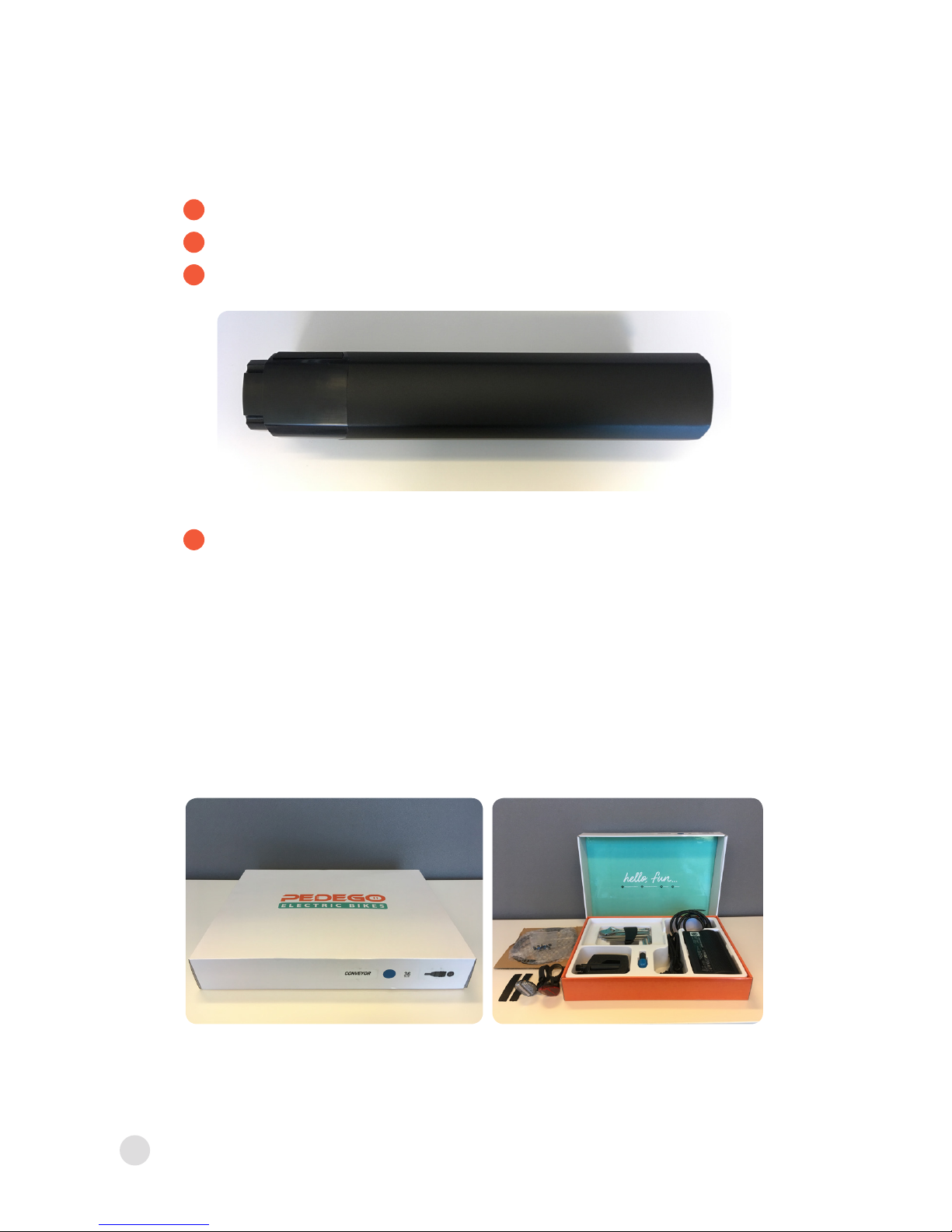
CARTON CONTENTS
Parts Kit
Owner’s Manual and Assembly Instructions
Battery Charger
Pedals
Front Disc Brake Rotor & Mounting Hardware
Front & Rear Reectors
Tool Kit
Touch Up Paint
Pedego Conveyor
Keys
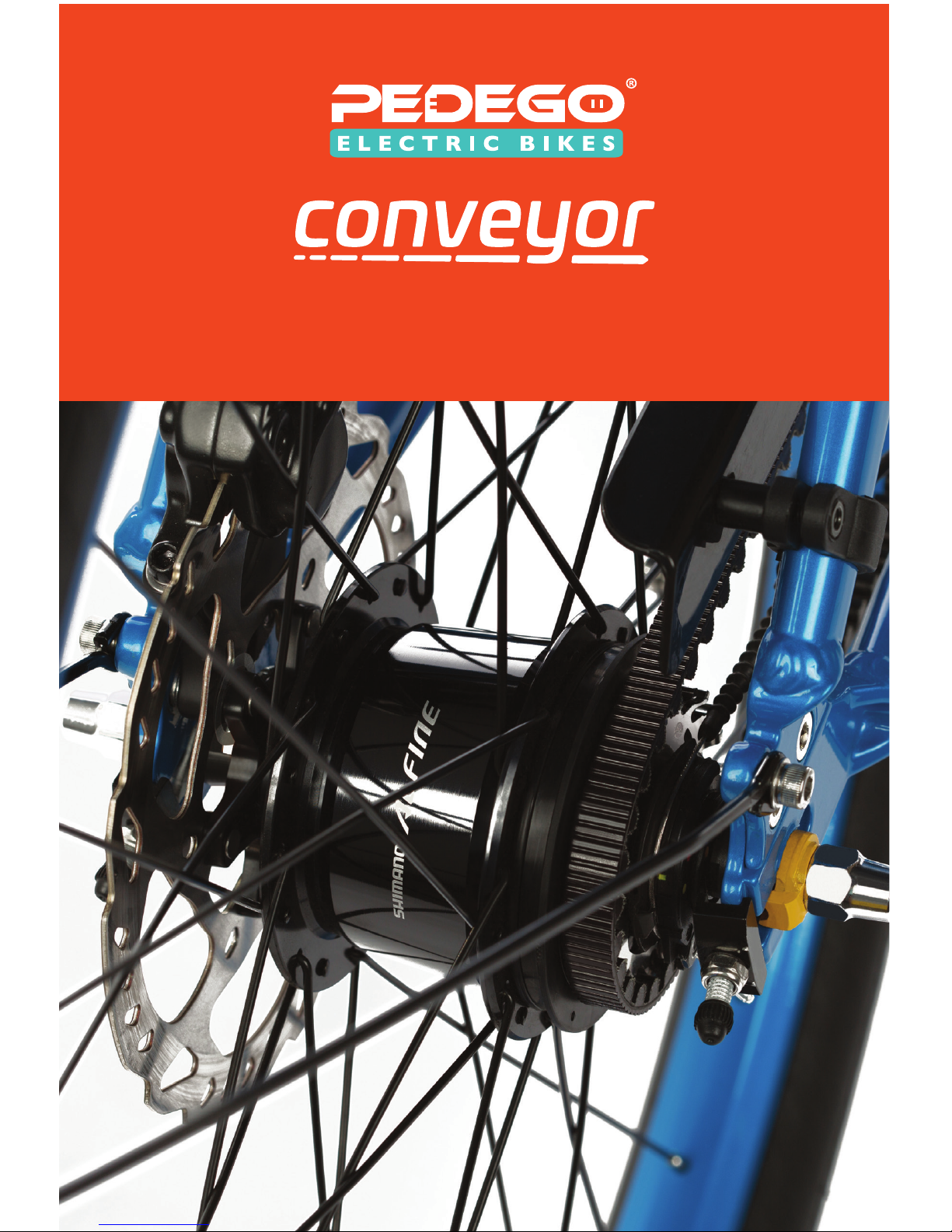
36V 13Ah (468 Wh) Lithium-Ion Battery
x2
x1
x1
x1
Carton Contents
Table of contents
Other Pedego Scooter manuals


