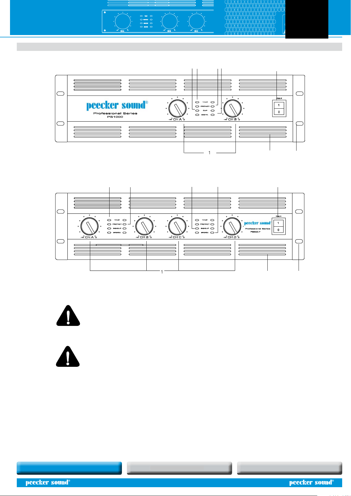
PROTECT
TEMP
SIG/CLIP
BRIDGE
CH C 0
-
CH A 0
-
CH B
0
-
POWER INPUTSERIAL NO:
EARTH
DC
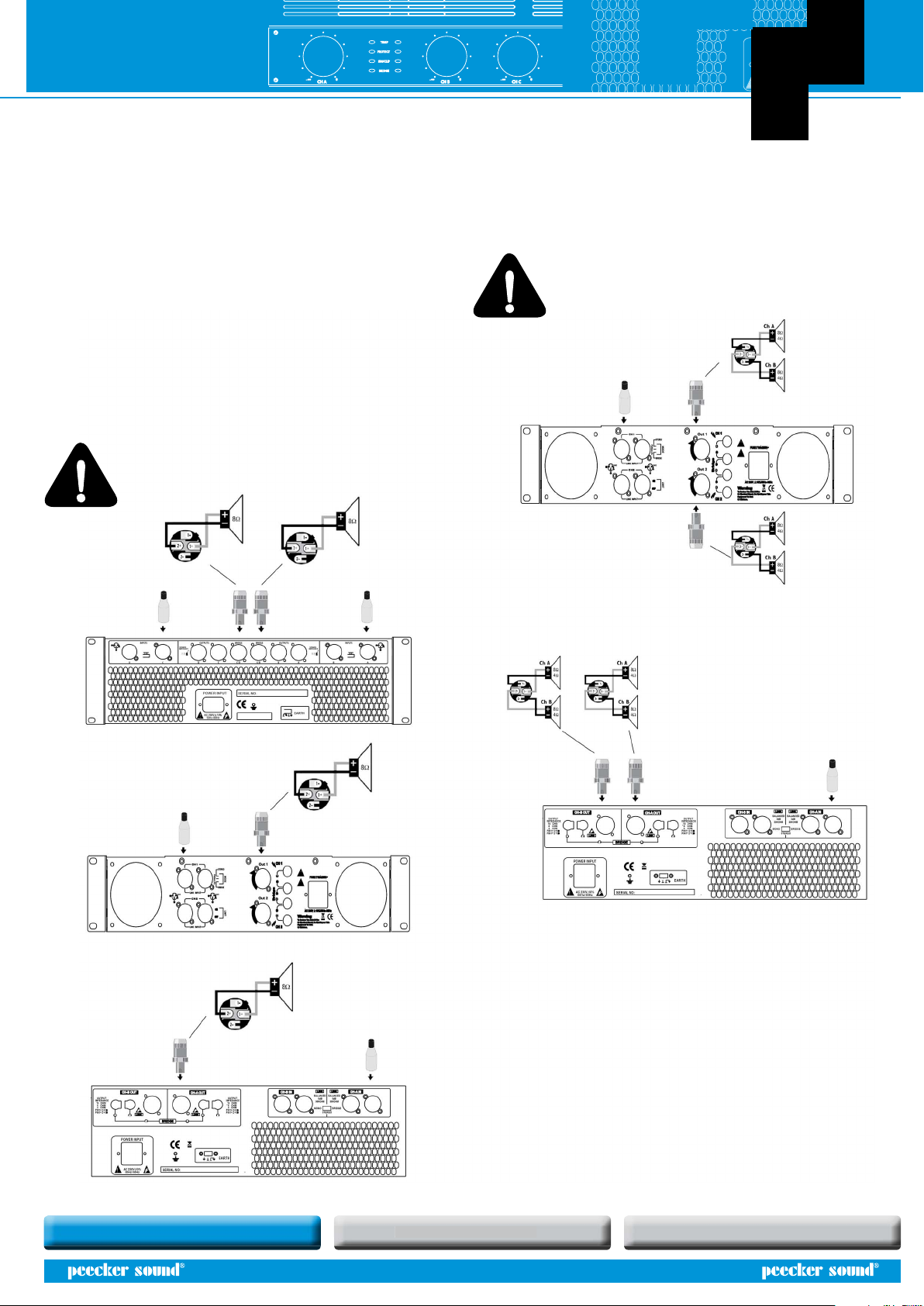
INPUTS
21
3
+GND
BRIDGE
STEREO
+
D C
BRIDGE MIN 8
C/D MIN 4
PIN1 2
PIN1 2
+
SPEAKER
IMPEDANCE
C-DA-B
OUTPUTS BRIDGE BRIDGE OUTPUTS
B A
BRIDGE MIN 8
A/B MIN 4
PIN1 2
PIN1 2
+
SPEAKER
IMPEDANCE
B A
21
3
+GND
BRIDGE
STEREO
INPUTS
AC 230V10%
50Hz-60Hz
SOUND REINFORCEMENT CONTROLLED RADIATION ACOUSTIC RESEARCH
CONTROLLED RADIATION
User’s Manual PS ampliers
3
2. DECLARATION OF CONFORMITY
This device complies with the requirements of the European Electromagnetic
Compatibility Directive 89/336/EEC and relevant 92/31/EEC amendment, as
well as the requirements of the Low Voltage Directive 72/23/EEC and relevant
93/68/EE amendment.
Regulations applied:
EN55103-1 (Emissions)
EN55103-2 (Immunity)
EN60065, Class I (Safety).
3. WARRANTY
Peecker Sound products are guaranteed against malfunction due to defective
materials or workmanship for a specied period of time, starting from the date
of original purchase. Should a malfunction occur during the warranty period,
the product will be repaired or replaced (at the manufacturer’s discretion) free
of charge. The shipping costs and related risks, and any loss during shipment
to authorized service centres are the responsibility of the customer. The
product will be returned to the customer with a carriage forward shipment.
Warranty terms
The warranty covers the appliance under its initial purchase in compliance
with the laws in force. The warranty is valid for 3 years, starting from the date
of receipt of the product. Peecker Sound reserves the right, in certain cases, to
decide to replace the appliance with another identical or similar product. The
warranty is not extended following a product failure. The warranty does not
cover any incidental or consequential damages, without limitation, caused to
persons or property during any period of inefficiency of the appliance.
Exclusions and limitations
The warranty does not apply to:
• any damage to exterior nishings or surfaces, aesthetic elements, or electric/
electronic parts resulting from negligent use of the product;
• malfunction resulting from incorrect or improper use of the product or from
transport without due care;
• malfunction resulting from repairs carried out by unauthorized persons or
service centres;
• malfunction due to circumstances that cannot be ascribed to manufacturing
defects of the appliance;
• plastic or glass parts, bulbs and the like, as well as all that can be regarded
as normal wear and tear. As regards circuit components (transistors, diodes,
etc.) the general terms set by the original manufacturers apply.
The following are also not covered by the warranty:
• damage caused by accidents, product modications, negligence or incorrect
connection
• damage that occurred during transport
• damage resulting from failure to comply with the instructions contained in
the user’s manual
• claims based on misrepresentations by the seller and any product whose
serial number has been rubbed o, modied or removed.
Receiving warranty service
To receive repair or replacement of the product under warranty, the customer
must deliver the product in its original packaging carriage paid to an
authorized Peecker Sound service centre together with the relevant proof of
purchase, i.e. bill of sale, receipt or invoice.
The warranty service and list of authorized service centres is available at the
address below:
Peecker Sound - “After Sales Service”
Via Monti Urali, 29 - 42100 Reggio Emilia (Italy)
Tel: +39 0522 557735 - Fax: +39 0522 391268
1. IMPORTANT SAFETY INSTRUCTIONS
This symbol indicates key operating instructions and
information requiring particular attention for correct use
of the product.
This symbol warns of dangerous voltage and the
consequent risk of electric shock. Take extra care and
proceed with caution.
1. Read carefully all the attached product documentation and keep for
further reference.
2. Heed the warnings.
3. Keep the packaging and check that all the material is in perfect
condition.
4. Do not use the product in the vicinity of water or pour water or any
other liquid on the amplier. Take care not to use it with wet hands or
with your feet in water.
5. Do not use near sources of heat such as radiators, stoves or other heat-
producing appliances.
6. Check that the power cable is intact and undamaged. Do not tread on
the cable and take care not to put any pressure on the plug.
7. Connect the plug to a properly earthed electric socket. Do not tamper
with the plug. Should the plug supplied not t your socket, have an
electrician replace it with the correct one.
8. Connect to the mains supply having identical voltage as that indicated
on the back of the amplier.
9. Install the amplier in compliance with the instructions.
10. Do not obstruct the air ducts.
11. Disconnect the appliance in case of storms or when not in use.
12. Wire exclusively as shown in the instructions.
13. Do not remove the upper or lower covers as this would expose the
user to the risk of electric shock.
14. Do not attempt to repair the appliance yourself but always seek the
assistance of qualied technicians.
15. Do not connect an input signal higher than that indicated in the
manual.
16. Do not connect the amplier output to the input of another channel.
17. Do not connect the amplier output to any other power source such as
batteries, power supply unit or mains outlets, regardless of whether the
amplier is switched on or o.
18. Clean with a dry cloth only.
19. The product must be handled by qualied technicians when:
• the power cable or the plug is damaged
• the product has been exposed to rain or humidity
• liquid has got inside the unit
• an object has fallen on the unit
• the unit has fallen and is damaged
• the appliance seems to be malfunctioning or is showing a marked
change in performance
20. Careful supervision is required if the product is used in the presence of
children or by unskilled adults.
21. This appliance may produce sound pressure levels damaging to the
hearing. Take the utmost care and do not use the product for long
periods of time at high or uncomfortable volume levels. Should
you experience any hearing loss or buzzing in your ears, consult an
audiometric specialist.