manuals.online logo
Brands
  1. Home
  2. •
  3. Brands
  4. •
  5. PEERLESS
  6. •
  7. Boiler
  8. •
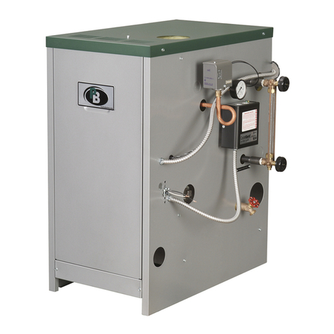
  9. PEERLESS SERIES GM Instruction manual

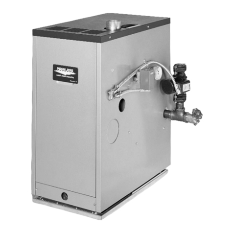
PEERLESS SERIES GM Instruction manual

GM
Boilers
Installation,
Operation b
Maintenance
Manual
PEEI_LESS*
CAST IRON BOILERS
Packaged Residential/Commercial Gas Fired, Hot
4 Sizes 5-8 Sections 228.0 to 399.0 MBH Input 82% Combustion Efficiency
Natural Gas
•Standing Pilot (5-6 section)
•Honeywell SmartValve ®Intermittent Ignition (5-8 section)
Natural Draft (Chimney) Venting
•Simplifies Installation
Steel Push Nipples
•Provide a Permanent Water Tight Seal Between Sections
•Unaffected by Petroleum and Other Contaminants
Deluxe Insulated Enameled Steel Jacket
•Reduces Boiler Heat Loss
•Completely Encloses Gas Valve, Burners and Controls for
Safe Operation
Front Located Controls and Return Piping
•Ideal for modular and multiple boiler installations
•Easy to service
Packaged Boiler
•Reduces Installation Time
Vertical Draft Hood
•Supports Combustion
Safety Controls
•Vent Safety ShutoffSwilch
•Flame RoUout Safety Shuto[]Switch
•Honeywell SmartValve °-_Intermittent Ignition
•Honeywell Operating Controls
• 30 PSI Sof('ty Relief Valve (unmounted)
• Vent Damper (5-6 section)
• Vertical Draft Hood
! STIIOI I_(llll{! iS II II'( ist(_r_,d Irademrlrk o[ t[I)IEt'IIH_I'II (_oI'lll)I I• Standing Pilot Ignition (5 6 section)
• Toco 0010 & 0012 Circulators (unmounted)
• Taco 0010 &0012 Zoning Circulators
with relay (unmounted)
• 50, 80 or 1O0 PSI Safety Reli@ Valve (unmounted)
•Probe _]pe LWCO (unmounted)
•Vent Dampt'r (7 8 section)
P_'t'll('ss I [t'tltt't (ompatly is pleoscd _o _[1_'1 ont' qJ dle most COml)reh('nsiv_, it,arr(ully i)rograms
i. _l,,._,,,/.._.-v.AllI',.,.,I_.._._¢o,,_._._,._./(,t,(_,-,.._,(_,,,.i(a(...,_t,-o,6oil,.,__,,c!.d,,. l,,.i.,_, o,,,__j_.a_ pr=_r=_RLESS _
It,(ut(ult!l A linlit('(I. 1_'11 Ijcor it,ettTemt!l on IIl_" ('_l.*;t itz)tl ._;t'cliotls i_ procid(,(I [or(ill cotnm('r('i(d ))oilers.
P_'_'rlt's_ I)rOi,M(,.s (t limit_'(l. !!f!'limt" iP(trr(ttll!l ()it tilt" ('(t.'_t irotl s('t'liotl.'_ Ql il.,_ r('siH{'r_ti(ll hol u,ot_'r
!)od_'1.'_. euld (t ltnlit_'(I. It'rl y('or w_trt(lllt!j ()It l/R' C(l_l it'otl .'%'cliotk'_ o] lt._ tt'aid('tllt(ll ._;l('(llll !)oi ('_._; ['_" _ ' CAST IRON BOILERS
_ttl(I t('tl !l('(tt" <'.\l('tlcl('(I It'(It I(ttlli('.s o_1 p_trt.'¢ lul(I led)or (trt" c_t,ailcl])l_,.]_)_" I_olt_ ¢l'.'_i(l('tll[(ll _ttl(I
conmlt,r(itd boik'rs, l)l(,(t_, cott._;tllt l'('('rl('ss l l_'(tt('r" (?OtlllXttly.Jbr (.oml)l(,t(, [t,ttttett_ll itl ()t'_llttltotL
Peerless Heater Company • 231 North Walnut Street * Boyertown, PA 19512-I021 •610-367-2153 * www.peerless-heater.com
FAB GM R2 {7'02 5M)
Pr,ltl.0 Irl U S A
1=
USING THIS MANUAL 1
A. INSTALLATION SEQUENCE ............. 1
B. SPECIAL ATTENTION BOXES ........... 1
PREINSTALLATION 2
A. ACCESSIBILITY CLEARANCES .......... 2
B. CLEARANCE FROM COMBUSTIBLE
CONSTRUCTION ..................... 2
C. COMBUSTION AND VENTILATION AIR .... 2
D. INSTALLATION SURVEY ............... 4
E. CIRCULATORS ....................... 4
E PLANNING THE LAYOUT ............... 4
A. BOILER SUPPLY AND RETURN .......... 6
B. SAFETY RELIEF VALVE ................ 7
C. PIPING FOR ZONED SYSTEMS .......... 8
D. EXPANSION TANK .................... 9
E. INDIRECT-FIRED WATER HEATER ........ 9
E FREEZE PROTECTION ................. 9
4, VENTING .... _ :
10
A. DRAFT HOOD ...................... 10
B. AUTOMATIC VENT DAMPER .............
INSTALLATION - GENERAL ............ 11
C. VENT PIPING AND CHIMNEY .......... 11
D. BOILER REMOVAL FROM COMMON
VENTING SYSTEM ................... 12
5_GAs _P|PJNG _':
A. WIRING ........................... 15
B. CIRCULATOR/ZONE VALVE WIRING ..... 15
C. LOW WATER CUTOFF ................ 15
A. GENERAL .......................... 21
B. CSD PART CF REQUIREMENTS ......... 21
C. CSD PART CW REQUIREMENTS ........ 21
D. CSD MODULAR AND MULTIPLE BOILER
REQUIREMENTS .................... 21
E. CSD PART CE ELECTRICAL
REQUIREMENTS .................... 22
23
A. COMPLETING THE INSTALLATION ...... 23
B. CONTROL DESCRIPTIONS ............. 27
C. ADJUSTMENT OF GAS PRESSURE
REGULATOR ....................... 27
D. CHECKING BURNER INPUT ............ 27
E. CHECK-OUT PROCEDURE ............. 28
A. SHUT-DOWN CAUSED BY PILOT OUTAGE,
VENT SAFETY SHUTOFF SWITCH OR
FLAME ROLLOUT SAFETY SHUTOFF
SWITCH ........................... 29
B. TROUBLESHOOTING GUIDES .......... 29
_O.MAINTENANCE 32
A. GENERAL .......................... 32
B. DAILY (WITH BOILER IN USE) .......... 32
C. WEEKLY (WITH BOILER IN USE) ........ 32
D. MONTHLY (WITH BOILER IN USE) ....... 32
E. ANNUALLY (BEFORE START OF HEATING
SEASON) .......................... 33
A. BASE ............................. 35
B. GAS MANIFOLD, ORIFICE SPUDS, AND
MAIN BURNERS ..................... 36
C. BLOCK AND FLUE COLLECTOR ......... 37
D. JACKET ........................... 38
E. CONTROLS, DRAFT HOOD AND
AUTOMATIC VENT DAMPER ........... 39
Follow the installation instructions provided in this
manual in the order shown. The order of these
instructions have been set in order to provide the
installer with a logical sequence of steps that will
minimize potential interferences and maximize safety
during boiler installation.
Indicates a condition or hazard which will cause
severe personal injury, death or major property
damage.
_.'t',J:[I,] r__ Ir*__l/ i _b?Ii[o] L'_I:[o).'4 ::_
Throughout this manual you will see special attention
boxes intended to supplement the instructions and make
special notice of potential hazards. These categories
mean, in the judgment of the Peerless Heater Company:
Indicates a condition or hazard which may cause
severe personal injury, death or major property
damage.
Indicates a condition or hazard which will or can
cause minor personal injury or property damage.
Indicates special attention is needed, but not directly
related to potential personal injury or property
damage.
Theequipmentmustbeinstalledinaccordancewithinstallationrequirementsoftheauthorityhaving
jurisdictionor,intheabsenceofsuchrequirements,tothecurrenteditionoftheNational Fuel Gas Code, ANSI
Z223.1/NFPA 54.
Where required by the authority having jurisdiction, the installation must conform to American Society of
Mechanical Engineers Safety Code for Controls and Safety Devices for Automatically Fired Boilers, ASME CSD-I.
Carefully read these instTuctions before beginning work. Understand all aspects of the installation. Contact your Peerless Heater
Company sales representative or customer service for help in answering questions.
This boiler must be installed by a qualified contractor. The boiler warranty can be voided if the boiler is not installed correctly.
r,_! P__] =k'-]_'tlHI l|&'J IN I!__,I ;5_,1=_IN =[<
Install boiler not less than 24" between the top and front
of the boiler and adjacent wall or other appliance, when
access is required for servicing. Do not install boiler on carpeting. Boiler installation
on carpeting is a fire hazard,
_e,]l [e,Zo]L'r_l:tlj.:']ld[o]_'Hf_,lL'111]Lrj:l_'_llllf,_'l/[o]L'_|:!l;
The design of this boiler is certified for alcove installation
with the following clearances from combustible
construction:
I Sides: 2"
2. Top of Jacket: 36"
3. Draft Hood: 6"
4. Vent Pipe: 6" (1" for Type B vent)
5. Rear of Jacket: 6"
Do not install this boiler on combustible flooring.
Boiler installation on combustible flooring is a fire
hazard.
6. If it is necessary to build a non-combustible floor pad
over top of an existing combustible floor, construct
pad as stated in the .National Fuel Gas Code
Handbook Part 6, Installation of Specific Equipment.
].
2.
Provide adequate facilities for combustion and
ventilation air in accordance with Section 5.3, Air for
Combustion and Ventilation, .National Fuel Gas
Code, or applicable provisions of the local building
code. Subsections 2 through 6 below are based on
National Fuel Gas Code requirements.
Definitions:
Unconfined Space: a space whose volume is not
less than fifty (50) cubic feet per 1000 Btu!hr of the
total input rating of all appliances installed in that
space. Rooms communicating directly with the space
in which the appliances are installed, through
openings not furnished with doors, are considered
part of the unconfined space.
Unusually Tight Construction: Construction
where:
a. Walls and ceilings exposed to the outside
atmosphere have a continuous water vapor
retarder with a rating of 1 perm or less with
openings gasketed or sealed, and
b. Weatherstripping has been added on openable
windows and doors, and
e. Caulking or sealants are supplied to areas such
as joints around window and door frames,
between sole plates and floors, between wall-
ceiling joints, between wall panels, at
penetrations for plumbing, electrical and gas
lines, and at other openings.
3. Appliances Located in Unconfined Spaces:
For installations in unconfined spaces with other
than unusually tight construction, the supply of air
for combustion and ventilation can usually be
considered adequate.
=
'qll
4. Unusually Tight Construction:
For equipment located in buildings of unusually tight
construction as defined on the previous page,
provide air for combustion and ventilation using the
methods described in 5a or 5b below.
5 Appliances Located in Confined Spaces:
a. All air from inside the building: Provide two
permanent openings communicating directly with
an additional room or rooms of sufficient volume
so that the combined volume of all spaces meets
the criteria for an unconfined space. Use the total
input of all gas utilization equipment installed in
the combined space in making this
determination.
Size each opening with a minimum free area of
one square inch per i000 Btu!hr of the total
rating of all gas utilization equipment in the
confined space, but not less than 100 square
inches. Begin with one opening 12 inches from
the top, and begin the other opening within 12
inches of the bottom of the enclosure. See Figure
1. Provide air openings with minimum
dimensions not less than three (3) inches.
b. All air from outside the building. Connect the
confined space with the outdoors in accordance
with methods i) or ii) below. Provide air openings
with minimum dimensions not less than three (3)
inches. Where ducts are used, make certain that
they are the same cross-sectional area as the free
area of the openings to which they connect.
Provide two permanent openings, one
commencing within 12 inches of the top and
one commencing within 12 inches of the
bottom of the enclosure. Connect the
openings directly or by ducts, with the
outdoors or spaces (crawl or attic) that freely
communicate with the outdoors.
Where directly communicating with the
outdoors (see Figure 2) or where
communicating to the outdoors through
vertical ducts (see Figure 3), size each
opening with a minimum free area of one (I)
square inch per 4000 Btu/hr of total rating of
all equipment in the enclosure.
Where communicating with the outdoors
through horizontal ducts, size each opening
with a minimum flee area of one (i) square
inch per 2000 Btu/hr of total input rating of
all equipment in the enclosure. See Figure 4.
12" max
TWO AIR OPENINGS:
Minimum
Free Area Each =
1 in2per 1000 Btuh
at Least 100 in2
3" m{n
BUILDING
Mustcommunicatefreely
with outdoors
Must not beunder
negativepressure
3" mill
12" max
Figure 1: Air Openings - All Air from Indoors
TWO AIR OPENINGS:
Minimum
Free Area Each =
1 in2per 4000 Btuh
3" min __
12" max,_
Figure 2: Air Openings -All Air Directly from
Outdoors
[_L 12" max
3" rain TWO AIR OPENINGS:
Minimum
Free Area Each =
Figure 3: Air Openings -All Air from Outdoors
through Vertical Ducts
3
| ill _T_t::]I_t--'_*]]_ [r_ITr_]
6,
7.
ii) Where the equipment has clearances of at
least one (I) inch from the sides and back
and six (6) inches from the front of the
appliance, the code allows one permanent
opening, commencing within 12 inches of
the top of the enclosure Connect the
opening directly with the outdoors or through
a vertical or horizontal duct to the outdoors
or spaces (crawl or attic) that freely
communicate with the outdoors, Size the
opening with a minimum free area of one
square inch per 3000 Btu/hr of the total input
rating of all equipment in the enclosure, and
not less than the sum of the areas of all vent
connectors in the confined space.
In calculating tree area of an opening, take into
account the blocking affect of louvers, grilles and
screens. Do not use screens smaller than 1/4" mesh.
If the free area is known, use this value in calculating
the size of the opening required. If it is not known,
assume that wood louvers provide 20_25% free area,
and metal louvers and grilles provide 60-75% free
area.
Remove sources of hydrocarbons (bleaches,
cleaners, chemicals, sprays, paint removers, fabric
softeners, etc.) from the boiler area. The vapors
generated by these substances can contaminate the
combustion air and contribute to shortened
boiler/vent system life.
12" max TWO AIR OPENINGS:
Minimum
3" min Free Area Each =
1 in_per 2000 Btuh
3" rain
12"max
Figure 4: Air Openings - All Air from Outdoors
through Horizontal Ducts
Iwl IlO_.llt;lll_'_ll[e]_l _."[IJ;{fj:li"
For new and existing installations, a Water Installation
Survey is available from Peerless Heater Company. The
survey will provide information on how a hot water
boiler works with your specific system and will provide
an overview of hot water system operation in general.
You can also use this survey to locate system problems
which will have to be corrected. To obtain copies of the
Water Installation Survey. contact your Peerless
representative.
I:;l! [s,]I :{e,LI JI_,_llie];_
The Series GM boiler is not equipped with a circulator
or a means to control circulator operation. Provide
circulator and zone controls, such as Taco zoning
circulator or Honeywell R845.
i;q "JIr±l L_IL_I1_[_1 i i : 11 II:VLeI Ii
Prepare sketches and notes of the layout to minimize the
possibility of interferences with new or existing
equipment, piping, venting and wiring.
4
--m__
I Provide a sound, level foundation. Locate boiler as
near to the chimney or outside wall as possible and
centralized with respect to the heating system.
2. Locate boiler in front of installation position before
removing crate.
3 Separate the wood shipping pallet from the boiler
base by removing two (2) hold-down bolts at each
end of the boiler base.
4. Move boiler into final position.
5
g! [_r_ll[:[;| ['.,ll;,11_[€Ir=q_im3[_s]_h II;[*]l!_.']
Design piping and size circulator(s) to suit the system. Refer to
Hydronics Institute Installation Guide 2000 and the Peerless
Water Installation Survey for guidance.
L'I I:{e]lg:l:t _.'llJ'.J',_l_'l:lL_lm];|:lllJ:|k_
Install boiler to protect the gas ignition system
components from water (dripping, spraying, etc.) during
appliance operation and service (circulator replacement,
condensate hap, control replacements, etc.).
1. Remove shipping nipple from supply tapping.
2. Install temperature-pressure gage with tee in
supply tapping. Nipple, tee, bushing and gage are
located in trim carton. See Figure 5.
3. Install drain valve. Remove jacket front panel.
Install drain valve with tee in return tapping. Nipple,
tee, bushing and drain valve are located in trim
carton. See Figure 7. Tee may be installed with run
in either horizontal or vertical orientation.
4. Install supply piping, return piping and circulator.
See Figure 6.
a. If boiler is installed above radiation level, provide
a low water cutoff device in the supply piping
above boiler. See Figure 6.
TEMPERATURE
PRESSURE
GAGE F1-1/2" TEE
7! 1/2" X 8"
NIPPLE
I/2"× 1/4"
BUSHING
Figure 5: Temperature-Pressure Gage Installation
COLD
WATER
FILL
Figure 6:
SUPPLY
ALTERNATE CIRCULATOR
LOCATION _
SHUTOFF_
VALVEPRESSURE//sHuToPE/F
REDUCNO / / VALVE J L
VALVE_ /
_AIR VENT
AIR ELIMINATOR
CHECK
VALVE _
-- .--_DD,-
RETURN I
CIRCULATOR ___
DRAIN
VAI VE _-.
Typical Supply and Return Piping
i_LOW WATER
/CUTOFF
/
! DRAFN
6
b,
c.
d,
When system return water temperature will be
below 130°F,,pipe the boiler with a bypass
arrangement to blend the system return and hot
supply to obtain at least 130°F entering the
boiler. For more information on bypass piping,
consult the Peerless Water Installation Survey.
If this boiler and dislTibution system is used in
conjunction with a refrigeration system, pipe the
chilled medium in parallel with the boiler and
install the proper valve to prevent the chilled
medium from entering the boiler. See Figure 8.
When the boiler is connected to heating coils
located in air handling units where they may be
exposed to refrigerated air circulation, install flow
contzol valves or other automatic means to
prevent gravity circulation of the boiler water
during the cooling cycle.
I:m [__'W_=ISlk'4I;|:lll:l= krl'-11.rd
I. Locate safet_ relief valve and nipple in tzim carton.
2. Install safety relief valve in 3/4 NPT tapping behind
supply tapping. Safety relief valve must be installed
with spindle in vertical position. See Figure 9.
Figure 7: Drain Valve Installation
CHECK VALVE
Pipe the discharge of safety relief valve to prevent
injury in the event of pressure relief, Pipe the
discharge to a drain. Provide piping that is the same
size as the safety relief valve outlet, LiN_
WATER tHrEE WAY
I_ci[LL[R VALVE
Figure 8: Parallel Hook-up with Water Chiller
SAFETY
SUPPLY _ RELIEF
VALVE
/
/
\/TO DRA_N
Figure 9: Safety Relief Valve Installation
7
1. See Figures i0 and 11 for basic zoned system
layouts. Circulators may be installed in either supply
or return piping. Refer to Peerless Water Installation
Survey for additional information.
2. Run each zone pipe down then up to zone to
prevent air accumulation in piping•
3. If required, provide means to isolate and drain each
zone separately.
3
FROM SYSTEM
ZONE ZONE ZONE
1 2 5
TO
BALANCING
VALVES
CONNECT TO
RETURN
(CIRCULATOR INLET)
H
Figure 10: Zone Piping with Zone Valves
ZC'r,!E _ '_:'-
i
i
' _ I 'F I
• d - i
I i
f• • t + 4
(_ :£) ['i bJE I:
Z! iL}
FROM SYS!EI',,/
I
!I
,. ,• L, _¸ I .• _ .2.
....................... ] 0
' -: 'i :t;
[ }
l
Figure 11: Zone Piping with Circulators
8
I_il 1:1t,1:1:1_4::in-.J:Tell d:loCiiI[el _
1, Consult the tank manufacturer's instructions for
specific information relating to tank installation. Size
the expansion tank for the required system volume
and capacity. See Table 5 in Section 11 for boiler's
water content,
2. Expansion tanks are available with built-in fill valves
and check valves for reducing supply water pressure
and maintaining minimum system pressure. Check
the design features of the tank and provide valves as
necessa_j.
Refer to Figure 6 for typical expansion tank piping.
€11 Ih_lD]lH=[t,,]ll_=l;lcID] |vA_U:_I/::Ilt I:1:!:_11_:
Boiler may be used as heat soume for indirect-fired
water heater. Refer to Figure 12 for typical piping.
Follow the instructions provided by the water heater
manufacturer. Pipe the water heater as if a separate
space heating zone.
For new or existing systems that must be freeze-
protected:
Use only inhibited propylene glycol solutions of up to
50% by volume with water. Ethylene glycol is toxic
and can attack gaskets and seals used in hydronic
systems,
1.
2.
3.
Glycol for hydronic applications is specially
formulated with inhibitors which prevent the glycol
from attacking metallic system components. Make
certain that the system fluid is checked for the
correct glycol concentration and inhibitor level.
Antifreeze solutions expand more than water For
example, a 50% by volume solution expands 4.8%
in volume for a temperature increase from 32°F to
180°E while water expands 3% with the same
temperature rise. Allowance must be made for this
expansion in system design.
For more information, consult the Peerless Water
Installation Survey and the antifreeze manufacturer.
SUPPLY TC
SYSTErvl
RE tURN FROV,
SYSTEbi
TTq II
ZONE
CIRCU LA TORS[}_8.._
v
HOT DOMESTIC
SUP'PLY
IN[I:C'F:SI FIRED
Wi- TER HEATER
",:. _},
},k: I',"
.', TF{ i;vP Y
S
. - J
>DRAIN
! F ' !:
Ii
L
Figure 12: Typical Piping with Indirect-Fired Water Heater
W! ID);_l_ilil[oIo]B
1,
2.
3.
The boiler is equipped with a draft hood designed to:
a. provide for the ready escape of flue gases from
the boiler in the event of no draft.
b. prevent a backdraft from entering the boiler.
c. control stack draft during operation.
The draft hood must be installed without alteration.
Make certain there are no obstructions to airflow to
the relief opening.
Position draft hood with 1" diameter hole in conical
portion of draft hood (for vent safety shutoff switch)
towards front right corner of boiler. Secure to flue
collector with sheet metal screws. See Figure 13.
The boiler is equipped with a vent safety shutoff
switch. The switch is shipped in a cloth bag attached
to the harness on the exterior of the boiler. Attach
switch to holes in the conical portion of the draft
hood using the screws provided in bag. See
Figure 13.
Vent safety shutoff switch wiring harness must extend
to vent safety shutoff switch without excessive slack.
To adjust harness length, squeeze strain relief bushing
to release from jacket. Adjust harness to proper
length. Reinsert strain relief bushing.
VENT SAFETY
SHUTOFFSCREWSMETALSHEETSWITCH_x
VENT SAFETY '_ /
SHUTOFF SWITCH "_
WlRINC HARNESS_
Figure 13: Draft Hood and Vent Safety Shutoff
Switch Installation
INCORRECT
I
L__,
,{},THEr_
k:_ _]IN,S
APPLIANCE-
CORRECT
Figure 14: Venting Multiple Appliances
10
[e,lqkV4:lL'hlii:,]l:Jh,_felF_qL'_le][_:ilLVJh'q=h,
1.
2.
3.
4.
Do not use one vent damper to control two or more
heating appliances. See Figure 14.
Follow these and the installation instructions included
with the vent damper. Observe the cautions and
warnings that accompany all instructions.
Provide minimum 6 inch clearance between
automatic vent damper and combustible
construction. Increase clearance if required by vent
damper manufacturer's instructions. Provide
adequate space for vent damper access and service.
The automatic vent damper can be mounted directly
onto the draft hood outlet or in vent piping close to
the boiler.
See Figure 15 for installation with vent damper
mounted in vertical position. See Figure 16 for
installation with vent damper mounted in horizontal
position. Mount the unit to avoid excessive heat on
the operator or condensation drips into the operator.
a. Orient the vent damper operator to facilitate
connection of the vent damper harness to
knockout on right side of boiler. See Figure 19.
b. Orient vent damper direction arrow in direction
of vent gas flow. Direction arrow must be visible
from front of boiler.
i,
2.
3.
4,
5,
6.
7.
Install vent piping in accordance with Part 7, Venting
of Equipment, National Fuel Gas Code, ANSI
Z223.1/NFPA 54 or applicable provisions of the local
building codes.
Inspect the existing chimney and lining for structural
soundness, corrosion and perforations. Repair as
necessary.
Install vent pipe to slope upward at least I/4" per
lineal foot between the draft hood outlet and the
chimney.
Before connection of joints, inspect the vent pipe
interior for foreign objects such as tools, equipment,
rags, etc. and remove if present.
Insert vent pipe into but not beyond the inside wall
of the chimney flue.
Do not connect vent connectors serving appliances
vented by natural draft into any portion of
mechanical draft systems operating under positive
pressure.
Support horizontal portions of the venting system to
prevent sagging by use of metal strapping or
equivalent means. Locate supports at no more than
four (4) foot intervals, or in accordance with vent
system manufacturer's installation instructions.
SLOPE UP
A MINIMUM
OF
PER FOOT_ \
AUTOMATIC
VENT
DAMPER_
AS REQUIRED
DRAFT
HOOD
RELIEF
OPENING
\\"DRAFT HOOD
OUTLET
Figure 15: Venting with Vent Damper in Vertical Position
11
AUTOMATIC /- VENT TO
SLOPE UP VENT /CHIMNEY
A MINIMUM DAMPER 7
OF 1/4" /[ I
PER FOOT _
NENN 7
O'CLOCK 1 O'CLOCK
POSITION_ , /-- POSITION
VJJ/// s DA',,'PER
HEAT ....-.'_ S OPERATOR
ZONEJ __O0_ECONDENSATION
O'CLOCK J _5 O'CLOCK
POSITION POSITION
DO NOT MOUNT DAMPER
OPERATOR IN SHADED REGION
SECTION A--A
Figure 16: Venting with Vent Damper in Horizontal Position
At the time of removal of an existing boiler, follow these
steps with each appliance remaining connected to the
common venting system placed in operation, while the
other appliances remaining connected to the common
venting system are not in operation:
a. Seal any unused openings in the common venting
system.
b. Visually inspect the venting system for proper size
and horizontal pitch and determine there is no
blockage or restriction, leakage, corrosion and other
deficiencies which could cause an unsafe condition.
C. Insofar as is practical, close all building doors and
windows and all doors between the space in which
the appliances remaining connected to the common
venting system are located and other spaces of the
building. Turn on any clothes dryers and any
appliance not connected to common venting system.
Turn on any exhaust fans, such as range hoods and
bathroom exhausts, so they will operate at maximum
speed. Do not operate a summer exhaust fan. Close
fireplace dampers.
d,
e.
g.
Place in operation the appliance being inspected.
Follow the lighting instructions. Adjust thermostat so
appliance will operate continuously.
Test for spillage at the draft hood relief opening after
5 minutes of main burner operation. Use the flame
of a match or candle, or smoke from a cigarette,
cigar, or pipe.
After it has been determined that each appliance
remaining connected to the common venting system
properly vents when tested as outlined above, return
doors, windows, exhaust fans, fireplace dampers and
any other gas-burning appliance to their previous
conditions of use.
Any improper operation of the common venting
system should be corrected so that the installation
conforms with the National Fuel Gas Code, ANSI
Z223.1/NFPA 54. When resizing any portion of the
common venting system, the common venting
system should be resized to approach minimum size
as determined using the appropriate tables located in
the chapter "Sizing of Category I Venting Systems,"
of the National Fuel Gas Code, ANSI Z223.1/NFPA 54.
12
I. Size and install the gas supply piping to provide a
supply of gas sufficient to meet the maximum
demand of all appliances without undue loss of
pressure between the meter and the boiler.
Maximum permissible gas supply pressure to the
boiler is 13.5 inches water column.
2. Determine the volume of gas to be provided to the
boiler Obtain this value by dividing the Btu per hour
rating (on the boiler rating plate) by the heating
value of the gas in Btu per cubic feet. Obtain the
heating value of the gas from the gas supplier. As an
alternative, use Table 1 to obtain the volume of gas
to be provided to the boiler.
Table 1: Input (Cubic Feet Per Hour)
Model Natural Gas
GM-05 228
GM 06 285
GM-07 342
GM-08 399
Natural gas based on I000 Btu/Cubic Foot.
3. Use the value obtained above as the basis for piping
sizing. Size the gas piping in accordance with Table
2. Consult the National Fuel Gas Code for other
sizing options.
Table 2: Capacity of Schedule 40 Pipe
Capacity of Schedule 40 pipe (cu. fl. per hour) with pressure
drop of 0.3 in. and specific gravity of 0.60. No allowance for
an ordinary number of fittings is required.
Pipe _/4_ 1_ 1t/4" 1½"
Length
Feet Pipe Pipe Pipe Pipe
I0 ! 278 I 520 1,050 1,600
20 190 i 350 I 730 I,i00
30 I 152 285 ; 590 890
40 130 ! 245 500 760
50 115 i 215 440 670
60 105 195 400 610
Multipliers to be used with the above table when the
specific gravity of the gas is other than 0.60:
Specific Gravity , . .0,50 0.55 0.60 0.65 0.70
Multiplier ........ 1.10 1.04 1.00 0.962 0.926
4. Connection of boiler to the gas piping system may
be made on the left side or top of the boiler. See
Figure 41 for jacket opening locations.
Use a pipe joint sealing compound that is resistant to
the action of liquefied petroleum gas. A non-resistant
compound may lose sealing ability in the presence of
this gas, resulting in a gas leak and fire or explosion
potential.
5.
6.
7.
Install a sediment trap. See Figure 17. Locate a tee
in the drop pipe at same elevation as the gas inlet
connection to the boiler Extend the drop pipe to a
pipe cap. As an alternate, the sediment trap may be
located in the boiler vestibule. See Figure 18.
Install a ground joint union ahead of the gas control
assembly to permit servicing of the control. Some
local codes require an additional equipment shutoff
valve when using the combination gas controls. If
your code requires such a valve, a suggested
location is shown in Figure 17 or 18.
Check piping for leaks. Use an approved gas
detector, a non-corrosive leak detection fluid or other
leak detection method. If leaks are found, turn off all
gas flow and repair as necessary.
When checking for leaks, do not use matches,
candles, open flames or other methods that provide a
source of ignition,This can ignite a gas leak,
resulting in fire or explosion,
EQUIPMENT
SHUTOFF
VALVE
JACKET
OROUND
JOINT
UNION __
SEDIMENT
TRAP _
FLOOR
lINE x\
I
Figure 17: Gas Connection to Boiler - External
13
8. Disconnect the boiler and its individual shut-off valve
from the gas supply piping system during any
pressure testing of that system at test pressure in
excess of 1/2 psig (3.5 kPa).
Isolate the boiler from the gas supply piping system
by closing its individual service valve during any
pressure testing of the gas supply piping system at
test pressure equal to or less than 1/2 psig (3.5 kPa).
9. Minimum permissible supply pressure for purposes of
input adjustment (Inches Water Column):
_ GM-07
Standing Pilot 4.8 5,5 ........
Intermittent 4.5 4.5 4.6 4.9
Ignition
10. Maximum permissible supply pressure to the boiler
(Inches Water Column):
All models 13.5"
Ec_'UIP'dk N
FiI,' - r_
_])IN r fz
' C/ J
-!
Figure 18: Gas Connection to Boiler - Internal
14
,d E.']II:lIF--[,._;IC,.I_g
This unit when installed must be electrically grounded in accordance with the requirements of the authority
having jurisdiction or, in the absence of such requirements, with the current edition of the National Electrical
Code, ANSI/NFPA 70.
r;l ITl_JI;] Ib,_[€
I. See Figure 19 for location of wiring and controls, use
Figures 22 and 23 to connect the boiler to a power
supply and the connect components to the boiler.
2. Connect the boiler to a separate, permanently live
electrical supply line with a fused switch.
3. Connect the vent damper harness to the polarized
connector in the boiler vestibule as shown in
Figure 19.
3. Figure 25 shows typical wiring for one or more
circulators.
4. Figure 26 shows typical wiring for zone valves.
Do not power zone valves directly from the boiler
transformer, Doing so will greatly reduce the life of
the transformer. Use a separate transformer sized to
handle the total of all zone valve electrical loads.
:J [e,]I_'{HI JIf_,'llie] -'_Y_[e]L_I=kVl_,l&vj =liVid|I;| h_[€
:l[e|_A!JI_1!!'-_1/ =1;i[H Ij I[*] ;I
1. A zone control is required to operate circulator(s)
when using a low voltage thermostat.
2. Taco Zoning circulator(s) can be used instead of
mounting separate circulator r_lay(s) (Figure 20).
Wire low water cutoff to turn off power to boiler. See
Figure 21 for Hydroleve1550 low water cutoff. Refer to
manufacturer's instructions for other low water cutoffs.
POLARIZED
CONNECTOR
DAMPER
HARNESS
THERMOSTAT
VOLTAGE
POWER SUPPLY
BOX WITH PLATE
MOUNTED TRANSFORMER
Figure 19: Wiring Details
15
.a[.11[=(M=[q,(;([_f-'1ml('4_i_rmi'
f FROM t
THERMOSTAT --
OR OPERATING
CONTROL
/
TO JUNCTION 115V 60HZ
BOX PINK AND POWER SUPPLY
GREY W_RES.
Figure 20: Taco Zoning Circulator Wiring
I f:J v' E,QIZ
FO HAIN
DISCONNECT S_'vl ICH
t
L2 _/ GXD
A •
/, TO TRAXSFORM P B[ A/,_ ,',!;F
WHFF WIltS [ :': ,'_:[S I _!l}
L2 SHO//'4 {}_J WI_N{] [}/ 1_'
Figure 21: Hydrolovel 550 Low Water Cutoff Wiring
16
- [_iR =iai=[_ d;t [,@',_'_i![(_]
(HOT) ?
TRANSFORMER
120VAC
f_c'Nwww_
24VAC
"- l: •
ii
ii
VENT I i
iiFLAM E
SAFETy i
LIMIT S_TC H CONTROL S_TCH
....
DAMPER STUB HARNESS _ _
YY
GAS VALVE t i
!
I_ _ ,
LADDER LEGEND L_
120 VAC _IRING (LINE) IGNITER L
..... 24 VAC WIRING (LOW) ELEMENT _ENSOR LGROUND
(pILOT
NOTES TUBING)
ALL _RING MUST COMPLY WrTH APPLICABLE CODES,
ORDINANCES AND REGULATIONS
bF ANY OF THE ORIGINAL WIRE AS SUPPLIED _TH THE APPLIANCE
MUST BE REPLACED, IT MUST BE REPLACED WITH WIRE
AS SHOWN OR _TS EQUIVALENT
VENT SAFETy_CGY _( _____ DAMPER PLUG OR VENT DAMPER
SHUTOF_yS_TCH _ OU_ HARNESS (WHEN USED)
=-R ..... ;; 'I_'_DAMPER STUB HARNESS
_1 _ o I -i
LIMIT i I _ I _ SERVICE FUSED
i i :S_TCH DISCONNECT
I , , ,' , J HOT
I I .' L _ TOMAN
JUNC TION I ILiI I I , _ _SV 60HZ DSCONNEC
BOX----.._ , I # " I " I _2 _ SWITCH
iJ r i,
40VA i i tL._
7}1, • ,,,
_! .... •
llllll ..... \
BR ' 2J'
_:iI\THESE,TEMSTOeE
LJllllkr-- 1 T ! SURPUEDBY_NSTALLER
i
i p
_ ' PR',IRR FLA_E
ROLLOUTSWPTCH
WIRE CODE
RED
ORANGE
BK BLACK
BR BROWN
W WHITE
GY GREY
GRGYWGREE_GREYWMrTE STRIPE
Pl PINK
pR PURPLE
PILO T
[
CONNECTION DIAGRAM LEGEND
24 VAC SiZE IB AWG TYPE CL2X WIPE
........ 120 VAC SIZE 14 AWG TYPE TW TgFN WIRE
......... 24 VAC SIZE 16 18 AWC TYPE TW/TFFN OR CL2X WiRE
HONEYWELL PILOT WIRING
Figure 22: Connection and Schematic Diagram, intermittent Ignition
1.
2.
3.
4.
5.
Thermostat calls for heat.
Limit senses boiler water temperature. Prevents
operation until water temperature falls approximately
15°F below the cut-out temperature.
Automatic vent damper (if used) opens. Damper
must be in open position when appliance main
burner(s) is operating.
Gas valve energizes.
a. Igniter on.
b. Pilot gas on, igniting pilot.
Pilot flame detected.
a. Igniter off.
b. Main gas on, igniting main burners.
Note: If pilot flame is not detected within 30 seconds,
the igniter is turned off for 30 seconds, and then turned
back on. If the pilot is not detected within 30 seconds,
the igniter and pilot gas are turned off for 5 minutes.
The sequence then resumes at Step 4a.
6. Call for heat ends.
a. Pilot and main gas off, extinguishing pilot and
main burners.
b. Automatic vent damper (if used) closes.
17

Other manuals for SERIES GM

1

This manual suits for next models

4

Other PEERLESS Boiler manuals

PEERLESS CAST 92 Instruction manual

PEERLESS

PEERLESS CAST 92 Instruction manual

PEERLESS SERIES GM Instruction manual

PEERLESS

PEERLESS SERIES GM Instruction manual
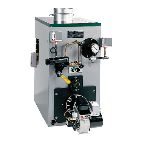
PEERLESS SERIES TC Instruction manual

PEERLESS

PEERLESS SERIES TC Instruction manual

PEERLESS PureFire PF-50 Instruction manual

PEERLESS

PEERLESS PureFire PF-50 Instruction manual

PEERLESS ECT SERIES Instruction manual

PEERLESS

PEERLESS ECT SERIES Instruction manual

PEERLESS Pinnacle PO-70 Instruction manual

PEERLESS

PEERLESS Pinnacle PO-70 Instruction manual

PEERLESS MI-e Series Instruction manual

PEERLESS

PEERLESS MI-e Series Instruction manual

PEERLESS SERIES WV-DV Instruction manual
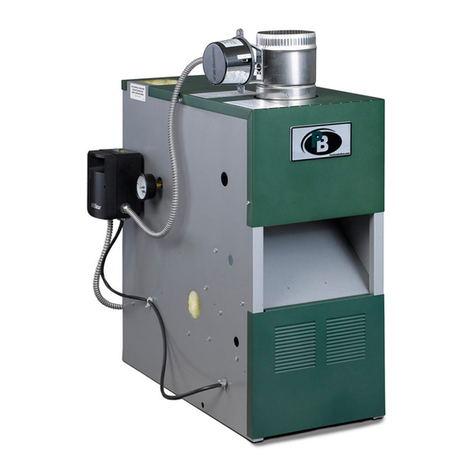
PEERLESS

PEERLESS SERIES WV-DV Instruction manual

PEERLESS WBV SERIES Instruction manual

PEERLESS

PEERLESS WBV SERIES Instruction manual

PEERLESS LC SERIES Instruction manual

PEERLESS

PEERLESS LC SERIES Instruction manual

PEERLESS Gas Boiler Instruction Manual

PEERLESS

PEERLESS Gas Boiler Instruction Manual

PEERLESS Pinnacle PI-399 User manual

PEERLESS

PEERLESS Pinnacle PI-399 User manual

PEERLESS PureFire PF-50 Instruction manual

PEERLESS

PEERLESS PureFire PF-50 Instruction manual

PEERLESS Series 63 Instruction manual

PEERLESS

PEERLESS Series 63 Instruction manual

PEERLESS Stainless Steel Gas Boilers Instruction manual

PEERLESS

PEERLESS Stainless Steel Gas Boilers Instruction manual

PEERLESS SERIES 211A Instruction manual

PEERLESS

PEERLESS SERIES 211A Instruction manual

PEERLESS SERIES 211A Instruction manual

PEERLESS

PEERLESS SERIES 211A Instruction manual

PEERLESS Series MI Instruction manual

PEERLESS

PEERLESS Series MI Instruction manual
PEERLESS PUREFIRE PFW-399 Instruction manual

PEERLESS

PEERLESS PUREFIRE PFW-399 Instruction manual

PEERLESS PureFire PF-200 Instruction manual

PEERLESS

PEERLESS PureFire PF-200 Instruction manual

PEERLESS Series MI Instruction manual

PEERLESS

PEERLESS Series MI Instruction manual

PEERLESS Pinnacle PI-199 Instruction manual

PEERLESS

PEERLESS Pinnacle PI-199 Instruction manual

PEERLESS SERIES DE Instruction manual

PEERLESS

PEERLESS SERIES DE Instruction manual

PEERLESS SERIES 62 Instruction manual

PEERLESS

PEERLESS SERIES 62 Instruction manual

Popular Boiler manuals by other brands

Termo 55 user manual

Termo

Termo 55 user manual

IDEAL he15 Installation and servicing

IDEAL

IDEAL he15 Installation and servicing

Keston 170 User instructions

Keston

Keston 170 User instructions

REXENER PR-200 user manual

REXENER

REXENER PR-200 user manual

Thermo-Dynamics Boiler TDE-10 Installation and maintenance manual

Thermo-Dynamics Boiler

Thermo-Dynamics Boiler TDE-10 Installation and maintenance manual

Chappee initia+ DUO 3.25 HTE Instruction manual for users and fitters

Chappee

Chappee initia+ DUO 3.25 HTE Instruction manual for users and fitters

Viessmann Vitodens 100-W operating instructions

Viessmann

Viessmann Vitodens 100-W operating instructions

Noritz CB199-DV owner's guide

Noritz

Noritz CB199-DV owner's guide

Raypak MVB TYPE B 504-2004 Installation & operating instructions

Raypak

Raypak MVB TYPE B 504-2004 Installation & operating instructions

Viessmann Vitodens 200-W System Installation and service instructions

Viessmann

Viessmann Vitodens 200-W System Installation and service instructions

Riello INSIEME EVOe 32 B/110 LN Installation and maintenance manual

Riello

Riello INSIEME EVOe 32 B/110 LN Installation and maintenance manual

Centrometal EKO-CKS P 140 Technical instructions

Centrometal

Centrometal EKO-CKS P 140 Technical instructions

Baxi Mainfour 24-24F Operating and installation instructions

Baxi

Baxi Mainfour 24-24F Operating and installation instructions

Quietside 090W1-NG installation manual

Quietside

Quietside 090W1-NG installation manual

Coopra TWIN80C installation manual

Coopra

Coopra TWIN80C installation manual

HearthStone H series instruction manual

HearthStone

HearthStone H series instruction manual

Fondital Nias Dual Line Tech BTN 24 Installation, use and maintenance

Fondital

Fondital Nias Dual Line Tech BTN 24 Installation, use and maintenance

Grundfos HURLEY ENGINEERING Hydro Multi-B Series Installation and operating instructions

Grundfos

Grundfos HURLEY ENGINEERING Hydro Multi-B Series Installation and operating instructions

manuals.online logo
manuals.online logoBrands
  • About & Mission
  • Contact us
  • Privacy Policy
  • Terms and Conditions

Copyright 2025 Manuals.Online. All Rights Reserved.