Pentair MYERS SRA-125 Troubleshooting guide

NOTE! To the installer: Please make sure you provide this manual to the owner of the equipment or to the responsible
party who maintains the system.
MODEL SRA-125/SRAX-125
DOUBLE-RAIL LIFT-OUT RAIL SYSTEM
INSTALLATION AND SERVICE MANUAL WITH PARTS LIST
For MG, WG(X), WGL, and Grinder Pumps for Effluent and Sewage.
Part # M-03-305 | © 2012 Pentair Pump Group, Ltd. | 11/13/12

M-03-305 11/13/12 2
CAUTION!
Read these safety warnings first before installing,
servicing, or operating any pump.
CALIFORNIA PROPOSITION 65 WARNING:
This product and related
accessories contain chemicals known to the
State of California to cause cancer, birth
defects or other reproductive harm.
GENERAL
1. Most accidents can be avoided by using
COMMON SENSE.
2. Read the operation and maintenance instruction
manual supplied with the pump.
3. Do not wear loose clothing that can become
entangled in the impeller or other moving parts.
4. This pump is designed to handle materials that
could cause illness or disease through direct
exposure.
Wear adequate protective clothing when working
on the pump or piping.
ELECTRICAL
5. To reduce the risk of electrical shock, pump must
be properly grounded in accordance with the
National Electric Code and all applicable state and
local codes and ordinances.
6. To reduce risk of electrical shock, disconnect the
pump from the power source before handling or
servicing.
7. Any wiring to be done on pumps should be done
by a qualified electrician.
8. Never operate a pump with a power cord that has
frayed or brittle insulation.
9. Never let cords or plugs lie in water.
10.Never handle connected power cords with wet
hands.
PUMPS
11.Pump builds up heat and pressure during
operation; allow time for pump to cool before
handling or servicing.
12.Only qualified personnel should install, operate or
repair pump.
13.Keep clear of suction and discharge openings.
DO NOT insert fingers in pump with power
connected.
14.Do not pump hazardous material not
recommended for pump (flammable, caustic, etc.).
15.Make sure lifting handles are securely fastened
each time before lifting.
16.Do not lift pump by the power cord.
17.Do not exceed manufacturer’s recommendation
for maximum performance, as this could cause the
motor to overheat.
18.Secure the pump in its operating position so it
cannot tip over, fall or slide.
19.Keep hands and feet away from impeller when
power is connected.
20.Submersible effluent, sewage and grinder
pumps are not approved for use in swimming
pools, recreational water installations, decorative
fountains or any installation where human contact
with the pumped fluid is common.
21.Do not operate pump without safety devices in
place.
22.For hazardous locations, use pumps that are listed
and classified for such locations.
IMPORTANT! Myers is not responsible for losses,
injury or death resulting from a failure to observe
these safety precautions, misuse or abuse of
pumps or equipment.
GENERAL INFORMATION
Lift-Out Models: These instructions cover the SRA-
125 with and without check valve. All lift-outs are
designed for pumps with 1-1/4" vertical discharge.
General Construction: The base as well as the
movable disconnect are made of cast iron. The guide
plate, top rail support and intermediate rail support
are made of stainless steel.
Lift-Out Chain: The two chain packages available
are galvanized and stainless steel. Each package
is designed to attach to the top of the pump and
also to the guide plate which is part of the movable
disconnect. Each package is designed to allow the
pump to be safely hoisted up the guide rail.
Rail Support Brackets: All the lift-outs are designed
to use 1" standard pipe for guide rails. A top rail
support is available to be mounted to the hatch frame.
Intermediate brackets are available for deep basins. It
is recommended that if the rail length is over 20 feet,
an intermediate bracket be installed.
Basin Covers: Myers has several types of basin
covers available for use with either fiberglass or
concrete basins. Basin hatch type covers are available
in either steel or aluminum construction. The basin
cover frame is designed to allow for mounting of rail
support brackets.
Basin Bottom: All concrete pipe basins must have a
smooth level troweled bottom for level mounting of
discharge casting.

M-03-305 11/13/12
3
Level Sensing Controls: The float level controls
maintain the basin sewage water level by controlling
pump turn-on and turn-off levels.
1. The lower turn-off control should be set so that the
pump stops at approximately the top of the pump.
Consult the factory for any settings below this
point.
2. The upper turn-on control should be set above the
lower turn-off control. The exact height between
the two controls is determined by the number
of pump starts desired and depth of the basin.
A maximum of 10 starts per hour should not be
exceeded.
3. The override control is set at a specified height
above the upper turn-on control.
4. The alarm control is set about 6" to 12" above the
override control.
5. No control should be set above the inlet invert.
CAUTION: Never enter pump chamber after
sewage or effluent has been in basin. Sewage
water can give off methane, hydrogen sulfide
and other gases that are highly poisonous. Myers
recommends using the rail lift-out system so that
no service is required inside the basin.
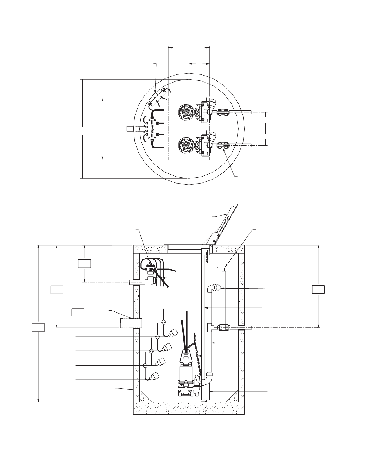
INSTALLING RAIL SYSTEM PARTS
Mounting Cover, Discharge Base and Rails
1. Set concrete cover with hatch opening in position.
2. Bolt top rail support plates to hatch frame. Two
1/4" bolts are required to attach each support.
3. Lower the base elbow into the basin.
4. Position the base elbow by dropping a plumb
line from center of pipe supports, located on
top rail support, to center of rail pins protruding
from the base elbow. Level the elbow flange in
two directions 90° to each other. Shims may be
required under the base in order to obtain this level
condition. Mark the position of the base hold-down
bolts through the holes in the base.
5. Move the base aside to allow drilling of the
concrete for 3/8" expansion bolts, 2" long. Move
the base over the bolt holes and recheck with level
and plumb line. Install expansion bolts.
6. Cut the pipe guide rails to the proper length and
install them between the pipe supports at the top
of the basin and the pins on the base. Guide rails
are to be Schedule 10 or Schedule 40, galvanized
or stainless steel.
7. Install discharge pipe as required by the particular
job specifications.
IMPORTANT: DISCHARGE PIPE AND GUIDE RAILS
MUST BE PARALLEL IF INTERMEDIATE GUIDE
BRACKET IS USED.
INSTALLING INTERMEDIATE
GUIDE BRACKET
(Required for each 20 feet of basin depth)
1. Remove guide rails and cut a piece from each
one. These pipes must be exactly the same length
and of a length that will permit installing the
intermediate guide bracket in the desired location.
2. Place the cut pieces of pipe over the guide rail pins
located in the base.
3. Set the intermediate guide bracket in position with
guides into pipe. Put U-bolt around discharge pipe
and tighten lightly.
4. Measure from joint on plug on intermediate guide
bracket to joint on plug on top rail support and
cut two rails to this length. Put rails in place and
tighten screws in top rail support.
5. Recheck rails; they must be straight and plumb.
Move intermediate guide bracket if necessary to
perfectly align rails. After alignment is secured,
tighten nuts on U-bolt.
6. If a second intermediate guide bracket is used, the
above procedure is followed for installation.
ATTACHING DISCONNECT TO PUMP
1. Bolt elbow onto pump volute at flange vise with
two 5/16-18UNC socket head cap screws.
2. Set lifting chain bail with one end on guide plate
eye bolt and other end on pump lifting eye.
INSTALLING PUMP AND DISCONNECT
1. Attach the lifting chain to the bail with clevis,
sliding the clevis along bail until the center of
gravity is found.
2. A hook is located on the top rail support to hold
the upper end of the chain when not in use.
3. Position pump so the guide rails are located in the
slots of the guide plate. Slowly lower the pump
down the guide rails to the base. The locating pins
(horizontal pins on sealing plate) should come to
seat in the inclined surface on the arms.
CAUTION: No persons should be in the sump basin
when pump is lowered into position!
Air Venting: Air tends to trap in the pump volute when
water rises in the sump or when the pump is lowered
into water after service. To vent off this air, a small
hole is drilled into the pump volute. Be sure this vent
hole is clean after any service work on pump.

M-03-305 11/13/12 4
INSTALLATION FOR RAIL SYSTEM
" x 2" lg.
Stud (4) Req’d.
Centerline Rails
and Base Studs
4"
7"
STUD PATTERN
FOR BASE
4"
17/16"
11/16"
101/2"
7"
23/4"
153/8"
31/4"
Hatch Cover Frame
To p Rail Support
Guide Rails, 1"
Intermediate Guide Bracket
(Req’d for depths over 20 f
eet)
Pump Guide Plate
2" NPT (female)
Lift-out Chain
Lift Bail
Ball Check Valve
(Bolts to pump)
27/8"
95/8"
14"
3/8

M-03-305 11/13/12
5
PARTS LIST
SIMPLEX TYPICAL INSTALLATION
Part Number Description
27170A001 DISCHARGE SEAL
05876A258 O-RING, ELBOWS
27156D000 BASE
27157C000 ELBOW, SRA-125
25073A004 GUIDE PIN
27171B000 GUIDE PLATE
19100A004 SCREWS, GUIDE PLATE
Part Number Description
21929A011 EYEBOLT, SST
06106A059 SCREWS, VOLUTE
27277A000 INSERT, SRA-125CV
050780001 BALL, SRA-125CV
27157C010 ELBOW, BRASS, SRAX-125
27171B001 GUIDE PLATE, BRASS, SRAX-125
Basin Cover, Struct. Plastic
or Fiberglass
SST Fasteners
Rail Support
Lift-out Chain
1-1/4" Anti-Siphon
Valve, PVC
1-1/4" Ball Valve, PVC Tr ue Union,
Blocked Type w/extension rod to
top
of basin)
Control Mounting Float Pole
High Water “Alarm” Level
1-1/4" Discharge Pipe, PVC
SCH.80
“On-Off” Level Control
SRA-125-CV Lift-out w/check valve
Simplex Junction Box
Conduit Flange
EY Conduit Seal
(req’d by others)
1-1/2" Conduit
Guide Rails, 1" Pipe
Fiberglass Basin
Invert
Inlet Adapter
(field installed)
18
24 or 30" Dia.
Discharge

M-03-305 11/13/12 6
DUPLEX TYPICAL INSTALLATION
1-1/4" Ball Valve, PVC
True Union, Blocked Type
Valve Extension Handle
1-1/4" Anti-Siphon
Valve (as req’d)
Guide Rails, 1"
Discharge Level
1-1/4" Discharge Pipe
Lift-out Chain
SRA-125-CV w/check
valve
48" Concrete Basin
(by others)
Pump “OFF” Level
Lead Pump “ON” Level
Lag Pump “ON” Level
High Water “Alarm” Level
Invert
Inlet Pipe
Duplex Junction Box
Alum. or Steel Basin Hatch
w/hinged access door
8 Min.
8 Min.
10
20 Min. Clear
Opening
Control Mounting
Bracket
48Ø30 Min.
Clear
Opening

THIS PAGE INTENTIONALLY LEFT BLANK

STANDARD LIMITED WARRANTY
Myers®warrants its products against defects in material and workmanship for a period of 12 months from the date
of shipment from Myers or 18 months from the manufacturing date, whichever occurs first - provided that such
products are used in compliance with the requirements of the Myers catalog and technical manuals for use in
pumping raw sewage, municipal wastewater or similar, abrasive free non-corrosive liquids.
During the warranty period and subject to the conditions set forth, Myers, at its discretion, will repair or replace to
the original user, the parts which prove defective in materials and workmanship. Myers reserves the right to change
or improve its products or any portions thereof without being obligated to provide such a change or improvement
for prior sold and/or shipped units.
Start-up reports and electrical schematics may be required to support warranty claims. Submit at the time of start
up through the Myers website: http://forms.pentairliterature.com/startupform/startupform.asp?type=m.
Warranty is effective only if Myers authorized control panels are used. All seal fail and heat sensing devices must
be hooked up, functional and monitored or this warranty will be void. Myers will only cover the lower seal and labor
thereof for all dual seal pumps. Under no circumstance will Myers be responsible for the cost of field labor, travel
expenses, rented equipment, removal/reinstallation costs or freight expenses to and from the factory or an
authorized Myers service facility.
This limited warranty will not apply: (a) to defects or malfunctions resulting from failure to properly install, operate or
maintain the unit in accordance with the printed instructions provided; (b) to failures resulting from abuse, accident
or negligence; (c) to normal maintenance services and parts used in connection with such service; (d) to units which
are not installed in accordance with applicable local codes, ordinances and good trade practices; (e) if the unit is
moved from its original installation location; (f) if unit is used for purposes other than for what it is designed and
manufactured; (g) to any unit which has been repaired or altered by anyone other than Myers or an authorized
Myers service provider; (h) to any unit which has been repaired using non factory specified/OEM parts.
Warranty Exclusions: MYERS MAKES NO EXPRESS OR IMPLIED WARRANTIES WHICH EXTEND BEYOND
THE DESCRIPTION ON THE FACE HEREOF. MYERS SPECIFICALLY DISCLAIMS THE IMPLIED WARRANTIES
OF MERCHANTABILITY AND FITNESS FOR ANY PARTICULAR PURPOSE.
Liability Limitation: IN NO EVENT SHALL MYERS BE LIABLE OR RESPONSIBLE FOR CONSEQUENTIAL,
INCIDENTAL OR SPECIAL DAMAGES RESULTING FROM OR RELATED IN ANY MANNER TO ANY MYERS
PRODUCT OR PARTS THEREOF. PERSONAL INJURY AND/OR PROPERTY DAMAGE MAY RESULT FROM
IMPROPER INSTALLATION. MYERS DISCLAIMS ALL LIABILITY, INCLUDING LIABILITY UNDER THIS
WARRANTY, FOR IMPROPER INSTALLATION. MYERS RECOMMENDS INSTALLATION BY PROFESSIONALS.
Some states do not permit some or all of the above warranty limitations or the exclusion or limitation of incidental
or consequential damages and therefore such limitations may not apply to you. No warranties or representations at
any time made by any representatives of Myers shall vary or expand the provision hereof.
740 East 9th Street
Ashland, Ohio 44805-1969
419-289-1144
www.femyers.com
Warranty Rev 12/11
Other manuals for MYERS SRA-125
1
This manual suits for next models
1
Table of contents
Other Pentair Grinder manuals