Pentair HYDROMATIC HPD200 Manual

NOTE! To the installer: Please make sure you provide this manual to the owner of the equipment or to the responsible
party who maintains the system.
RETROFIT SYSTEMS
INSTALLATION AND SERVICE MANUAL
Engineered for quick and easy replacement of existing
progressive cavity grinder systems.
• Fully assembled
• Uses existing ball valve and latch
• Uses existing underground wiring and alarm panel
This manual covers the following retrofit systems:
• HPD200 Float Control
• HPD200 Pressure Control
• HPGR200 Float Control
• HPGR200 Pressure Control
Item # E-03-482 | Part # 5625-482-1 | © 2014 Pentair Ltd. | 03/28/14
HPD200
Pressure Control
Shown

2
General
Information
ATTENTION: This manual
contains important information for
the safe use of this product. Read
this manual completely before
using this product and refer to it
often for continued safe product
use. DO NOT THROW AWAY
OR LOSE THIS MANUAL. Keep
it in a safe place so that you may
refer to it often.
Check local codes and
requirements before installation.
WARNING – Before handling
these pumps and controls, always
disconnect the power first. Do
not smoke or use sparkable
electrical devices or flames in a
septic (gaseous) or possible septic
sump.
CALIFORNIA PROPOSITION
65 WARNING:
This product and
related accessories contain
chemicals known to the State of
California to cause cancer, birth
defects or other reproductive
harm.
Installation
Instructions
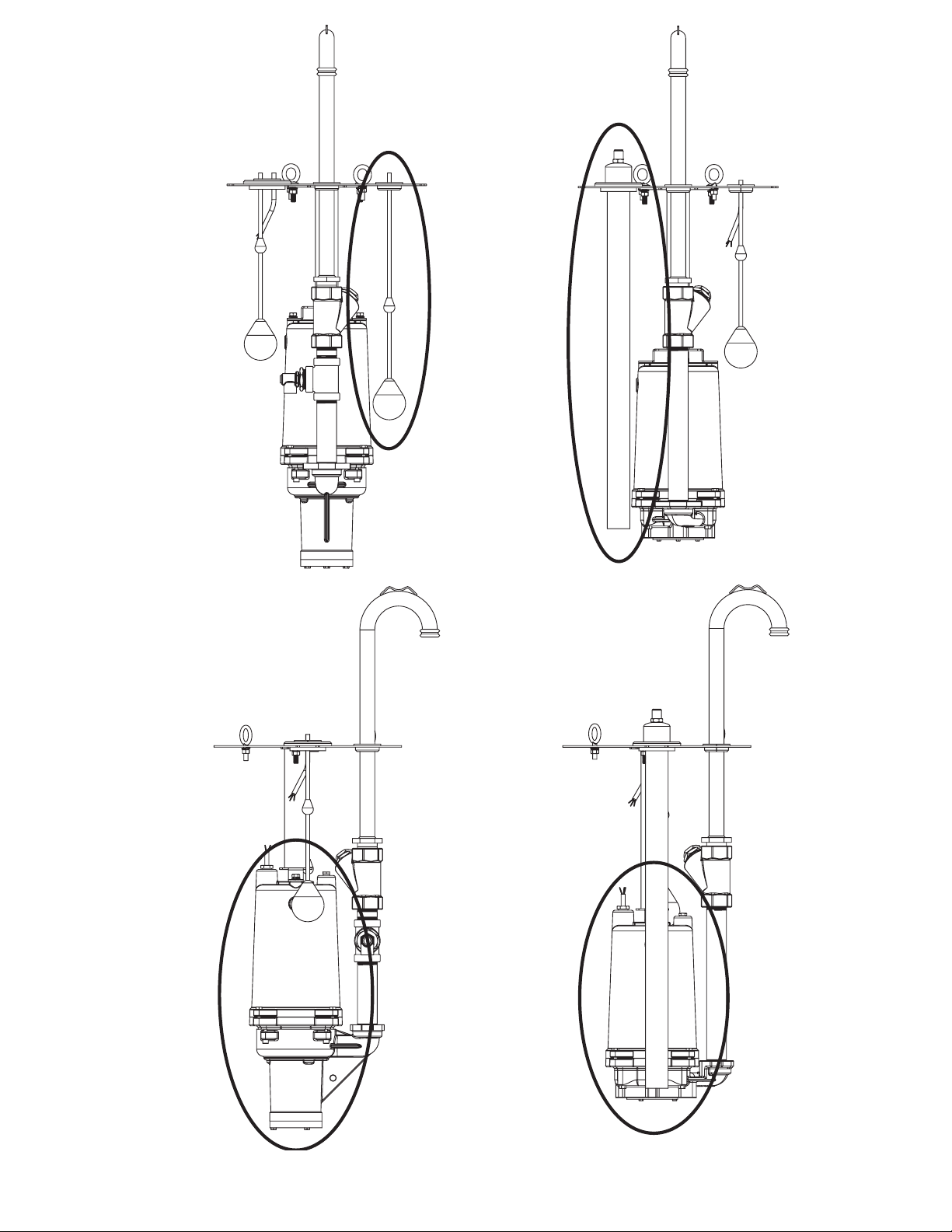
This manual covers retrofit
systems with either semipositive
displacement (HPD200) or
centrifugal (HPGR200) grinder
pumps using either pressure
controls or mechanical floats.
Please make sure you know which
system you are installing.
11. Attach cover with screws,
sleeves and washers provided.
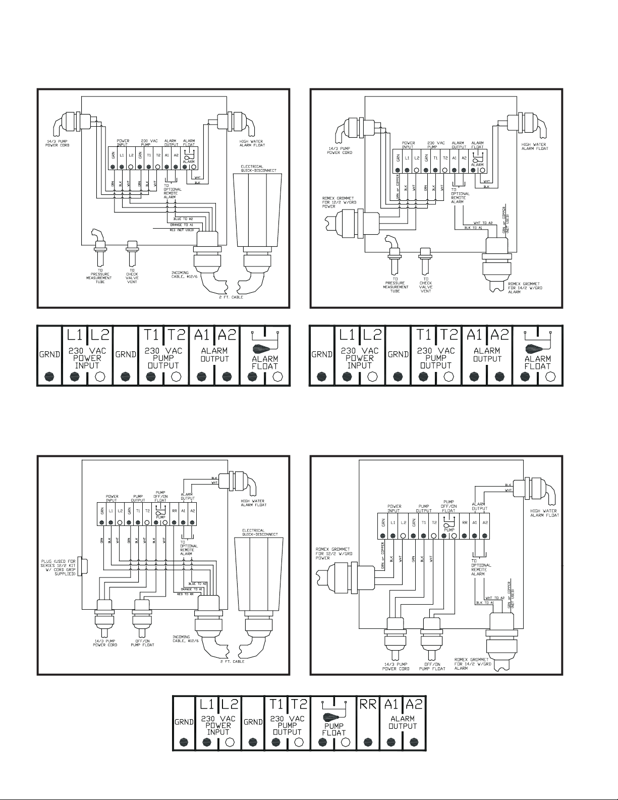
12. Power, control cords, pressure
tubing (for PCP units only)
and high water alarm to be
routed through junction box.
13. Properly calibrate operation
of the unit by ensuring that
the liquid level in the basin
is at its lowest level when
the control panel cycles off.
Make sure to cut off excess
pressure tubing to prevent
condensation from forming
inside tubing.
Electrical Note: Ensure that
existing wiring is adequate for
the pump service requirements.
Pump Full Load
Amps
Circuit
Breaker
HPD200 12 20 amp
HPGR200 15 20 amp
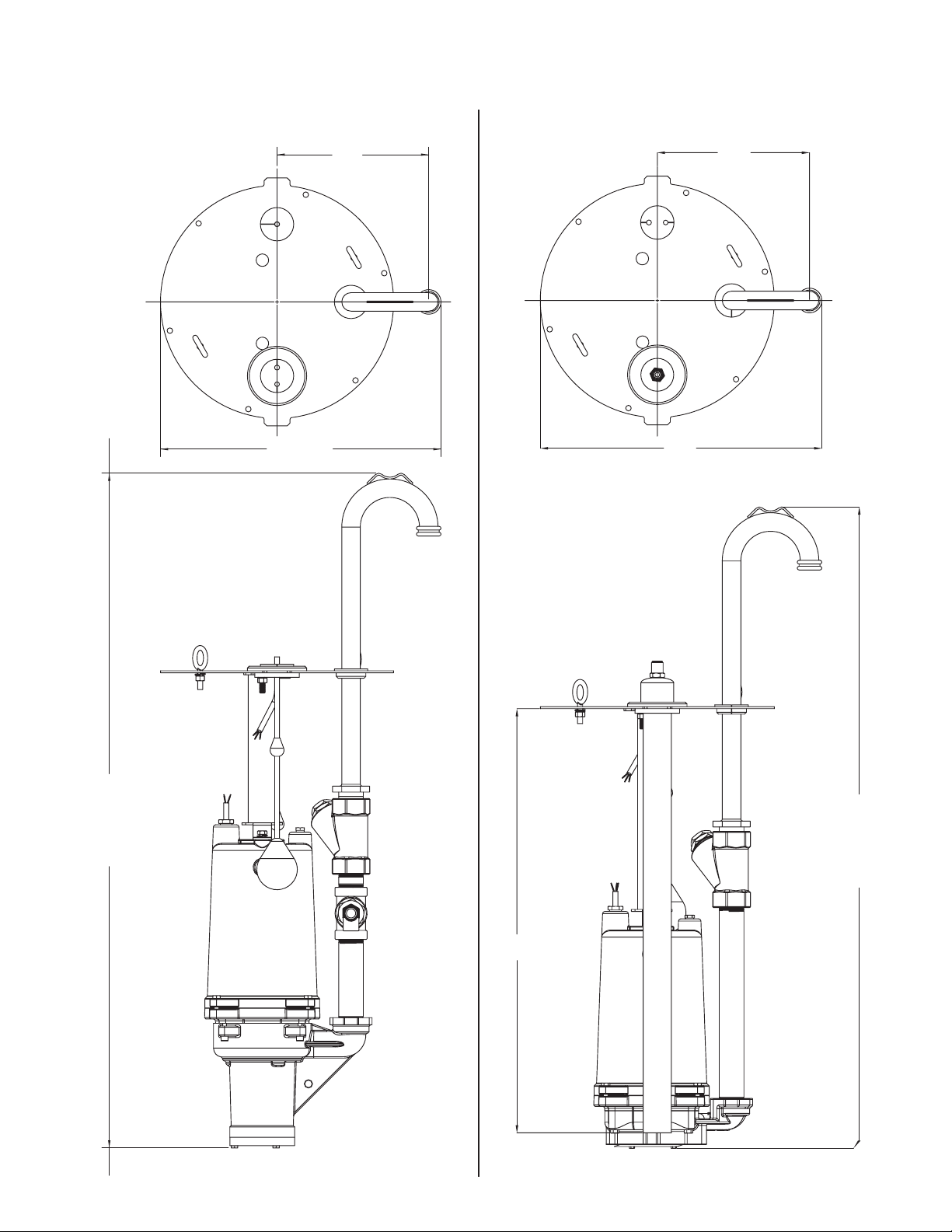
Grinder Installation
Instructions
1. Remove existing pump and
pipe system.
2. Make sure pump compartment
is clean of any debris.
3. Clean bolt hole (mating)
surface.
4. Make sure there is sufficient
amount of power/control/
alarm cord to be able to
splice into power/control/
alarm cords at the new
junction box.
5. Lift preassembled unit into
place using lift rope supplied.
6. Be sure that gasket stays in
place beneath cover.
7. Grease O-ring.
8. Guide tabs will line up with
existing alignment brackets.
Retrofit system discharge
piping should mate with
existing female socket.
9. After gooseneck is lined
up directly above ball
valve socket, drop into
place. Make certain that
adapter is forced all the
way into socket to ensure
a pressure-tight seal.
10. Rotate ball valve handle/latch
to secure piping and open
valve. If gooseneck is not
completely forced into the
female socket as described
above, ball valve handle/latch
will not close completely over
gooseneck piping.

3
Pressure ControlFloat Control
Semipositive Displacement Pump
(HPD200)
Centrifugal Pump
(HPGR200)

4
Incoming 12/6 Power Cord
Terminal LabelTerminal Label
Incoming 12/2 or 14/2 Power Cord
Part No. 27480A104
Retr
ofit Float Level Control Junction Box Wiring Diagram
Retrofit Pressure Level Control Junction Box Wiring Diagram
Par
t No. 27480A300 Part No. 27480A200
Incoming 12/6 Power Cord Incoming 14/2 Power Cord
Terminal Label

5
28.55
(REF.)
10.25
18.96
HPD200
45.63"
(APPROX.)
HPGR200
45.00"
(APPROX.)
10.25
19.00 (REF.)
HPD200 Shown HPGR200 Shown
HPGR200
45.00"
(APPROX.)
HPD200
45.63"
(APPROX.)
Dimensions
Float Control Pressure Control

6
ORDERING REPLACEMENT PARTS: Product improvements are made from time to time. The latest part design will be furnished as long as it is
interchangeable with the old part. When ordering replacement parts, always furnish the following information: (1) pump serial number, (2) pump model and size,
(3) part description, (4) part number, (5) impeller diameter (if ordering impeller), (6) quantity required and (7) shipping instructions.
Item Part No. Description Qty.
121920C017 Cover – Retrofit System 1
221925A008 Grommet – 1-1/4" Discharge 1
324335A006 Grommet – Pipe 1-1/2" 1
421925A006 Plug – Pump/Float Cables 1
527580A015 Float – Alarm, 15' lg. 1
605004A124 Bushing – Pipe, 1-1/2" x 1" SST 1
721929A012 Bolt – Eye, 3/8" SST 2
805454A015 Washer – Lock, 3/8" SST 5
919109A018 Nut – 3/8" SST 5
10 23019252100 Rope – 3/8" Poly 15 ft.
11 23150074000 Tape – Foam Gasket 4 ft.
12 26517C013 Adapter – Pump Support (HPGR200) 1
26517C012 Adapter – Pump Support (HPD200) 1
13 05660A033 Bolt – Carriage, 3/8" SST 2
14 27480A300 Panel – Junction Box for Incoming 12/6 Power Cord 1
27480A200 Panel – Junction Box for Incoming 14/2 Power Cord 1
15 26465D800 Pump – HPGR200 1
27315D812 Pump – HPD200 1
16 05917A139 Pipe – 1-1/4" x 2" SST (HPD200 Only) 1
17 05917A212 Pipe – 1-1/4" x 14-7/8" SST (HPGR200) 1
05917A211 Pipe – 1-1/4" x 6-11/16" SST (HPD200) 1
18 21903A012 Valve – Ball Check, 1-1/4" 1
Item Part No. Description Qty.
19 22418A016 Elbow – 1-1/4" Discharge, SST 1
20 05126A059 Tee – 1-1/4" SST (HPD200 Only) 1
21 05004A120 Bushing – Pipe, 1-1/4" x 1/2" SST (HPD200 Only) 1
22 149850001 Valve – Relief 1/2" (HPD200 Only) 1
23 005090011 Tube – Pressure, 1/4" O.D. 15 ft.
24 05737A027 Cap – Pipe, 1-1/2" PVC 1
25 13126A207 Pipe – 1-1/2" x 30" PVC 1
26 18696A028 Connector – Pressure Tube 1
27 19100A800 Screw – 5/16" x 2-1/4" SST 6
28 05151A426 Ferrule – 1/2" O.D. x 3/4" Lg. SST 6
29 05030A263 Washer – 5/16" SST 6
30 21903A100 Valve – Anti-Siphon 1
HPD200 Pressure Control System Shown
19
1
2
3
4
5
30
6
16
18
17
12
25
24
26
23
22
21
20
15
10
7
98
13
45°
VALV E
PUMP
NOTE: CHECK
VALVE MUST BE
INSTALLED PER
ILLUSTRATION
29 28
14
NOTE: SHIPPED LOOSE IN CARTON FOR
OPTIONAL CUSTOMER INSTALLATION
11
Pressure Control Retrofit System Replacement Parts

7
ORDERING REPLACEMENT PARTS: Product improvements are made from time to time. The latest part design will be furnished as long as it is
interchangeable with the old part. When ordering replacement parts, always furnish the following information: (1) pump serial number, (2) pump model and size,
(3) part description, (4) part number, (5) impeller diameter (if ordering impeller), (6) quantity required and (7) shipping instructions.
Item Part No. Description Qty.
121920C017 Cover – Retrofit System 1
221925A008 Grommet – 1-1/4" Discharge 1
324335A006 Grommet – Pipe 1-1/2" 1
421925A006 Plug – Pump/Float Cables 1
527599A020 Float – Control, 25' lg. 2
605004A120 Bushing – Pipe, 1-1/4" x 1/2" SST (HPD200 Only) 1
721929A012 Bolt – Eye, 3/8" SST 2
805454A015 Washer – Lock, 3/8" SST 5
919109A018 Nut – 3/8" SST 5
10 23019252100 Rope – 3/8" Poly 15 ft.
11 23150074000 Tape – Foam Gasket 4 ft.
12 26517C013 Adapter – Pump Support (HPGR200) 1
26517C012 Adapter – Pump Support (HPD200) 1
13 05660A033 Bolt – Carriage, 3/8" SST 2
14 14985D001 Valve – Relief, 1/2" (HPD200 Only) 1
15 26465D800 Pump – HPGR200 1
27315D812 Pump – HPD200 1
Item Part No. Description Qty.
16 05917A212 Pipe – 1-1/4" x 14-7/8" SST (HPGR200) 1
05917A211 Pipe – 1-1/4" x 6-11/16" SST (HPD200) 1
17 21903A012 Valve – Ball Check, 1-1/4" 1
18 22418A016 Elbow – 1-1/4" Discharge, SST 1
19 19100A800 Screw – 5/16" x 2-1/4" SST 6
20 05151A426 Ferrule – 1/2" O.D. x 3/4" Lg. SST 6
21 05030A263 Washer – 5/16" 6
22 21903A100 Valve – Anti-Siphon 1
23 21925A000 Plug – Float Cables 1
24 05004A124 Bushing – Pipe, 1-1/2" x 1" SST 1
25 27480A104 Panel – Junction Box 1
26 05126A059 Tee – 1-1/4" SST (HPD200 Only) 1
27 05917A139 Pipe – 1-1/4" x 2" SST (HPD200 Only) 1
HPGR200 Float Control System Shown
25
20
21
19
45°
VALVE
PUMP
NOTE: SHIPPED LOOSE IN CARTON FOR
OPTIONAL CUSTOMER INSTALLATION
NOTE: CHECK
VALVE MUST BE
INSTALLED PER
ILLUSTRATION
3
1
2
4
5
16
17
15
11
18
12
7
98
10
13
23
HPD200
only
14
27
6
26
24
22
Float Control Retrofit System Replacement Parts

740 EAST 9TH STREET 490 PINEBUSH ROAD, UNIT #4
ASHLAND, OHIO, USA 44805 CAMBRIDGE, ONTARIO, CANADA N1T 0A5
419-289-1144 800-363-PUMP
WWW.HYDROMATIC.COM
Warranty Rev. 12/13
STANDARD LIMITED WARRANTY
Pentair Hydromatic® warrants its products against defects in material and workmanship for a period of 12 months
from the date of shipment from Pentair Hydromatic or 18 months from the manufacturing date, whichever
occurs first – provided that such products are used in compliance with the requirements of the Pentair Hydromatic
catalog and technical manuals for use in pumping raw sewage, municipal wastewater or similar, abrasive-free,
noncorrosive liquids.
During the warranty period and subject to the conditions set forth, Pentair Hydromatic, at its discretion, will repair
or replace to the original user, the parts that prove defective in materials and workmanship. Pentair Hydromatic
reserves the right to change or improve its products or any portions thereof without being obligated to provide such
a change or improvement for prior sold and/or shipped units.
Start-up reports and electrical schematics may be required to support warranty claims. Submit at the time of start up
through the Pentair Hydromatic website: http://forms.pentairliterature.com/startupform/startupform.asp?type=h.
Warranty is effective only if Pentair Hydromatic authorized control panels are used. All seal fail and heat sensing
devices must be hooked up, functional and monitored or this warranty will be void. Pentair Hydromatic will cover
only the lower seal and labor thereof for all dual seal pumps. Under no circumstance will Pentair Hydromatic be
responsible for the cost of field labor, travel expenses, rented equipment, removal/reinstallation costs or freight
expenses to and from the factory or an authorized Pentair Hydromatic service facility.
This limited warranty will not apply: (a) to defects or malfunctions resulting from failure to properly install, operate or
maintain the unit in accordance with the printed instructions provided; (b) to failures resulting from abuse, accident
or negligence; (c) to normal maintenance services and parts used in connection with such service; (d) to units that
are not installed in accordance with applicable local codes, ordinances and good trade practices; (e) if the unit is
moved from its original installation location; (f) if unit is used for purposes other than for what it is designed and
manufactured; (g) to any unit that has been repaired or altered by anyone other than Pentair Hydromatic or an
authorized Pentair Hydromatic service provider; (h) to any unit that has been repaired using non factory specified/
OEM parts.
Warranty Exclusions: PENTAIR HYDROMATIC MAKES NO EXPRESS OR IMPLIED WARRANTIES THAT EXTEND
BEYOND THE DESCRIPTION ON THE FACE HEREOF. PENTAIR HYDROMATIC SPECIFICALLY DISCLAIMS THE
IMPLIED WARRANTIES OF MERCHANTABILITY AND FITNESS FOR ANY PARTICULAR PURPOSE.
Liability Limitation: IN NO EVENT SHALL PENTAIR HYDROMATIC BE LIABLE OR RESPONSIBLE FOR
CONSEQUENTIAL, INCIDENTAL OR SPECIAL DAMAGES RESULTING FROM OR RELATED IN ANY MANNER TO
ANY PENTAIR HYDROMATIC PRODUCT OR PARTS THEREOF. PERSONAL INJURY AND/OR PROPERTY DAMAGE
MAY RESULT FROM IMPROPER INSTALLATION. PENTAIR HYDROMATIC DISCLAIMS ALL LIABILITY, INCLUDING
LIABILITY UNDER THIS WARRANTY, FOR IMPROPER INSTALLATION. PENTAIR HYDROMATIC RECOMMENDS
INSTALLATION BY PROFESSIONALS.
Some states do not permit some or all of the above warranty limitations or the exclusion or limitation of incidental or
consequential damages and therefore such limitations may not apply to you. No warranties or representations at any
time made by any representatives of Pentair Hydromatic shall vary or expand the provision hereof.
This manual suits for next models
1
Table of contents
Other Pentair Grinder manuals