manuals.online logo
Brands
  1. Home
  2. •
  3. Brands
  4. •
  5. PENTRON
  6. •
  7. Cassette Player
  8. •
  9. PENTRON HF-400 User manual

PENTRON HF-400 User manual

PHoToFACT* FolJ.t
o
o
z\t
g ri.
c,L
F
qJ
G 111
4'e
=
GENERAL I NFORMATION
The Pentron Model IIF-400 utilizes mechanical and electrical facilities for making and
playing back tape recordings. Since this unit employs the Pentron TM-56 tapetransport mech-
anism. this service manual may be used when servicing the mechanical functions of any re-
corder using the TM-56 mechanism.
This recorder has two speeds (3 3/ 4 and 7 I/ 2 inches per second) and is designed for
duai track recordings, giving two full length recordings on a single reel of recording tape.
Any size reel up to ?" may be used on this machine. A VU Meter is used to simplify ttre ie-
cording level setting. Recordings can be madg from a radio, television receiver or phono-
graph. in addition to those made directly from the microphone. Recordings can be played back
through the self-contained speakers or an external speaker may be used through use of the
"Ext. Spkr. " jack.
Model HF-400 is designed to operate on 60 cycle, 110 to 125 voits, AC supply only. Be-
fore connecting to your line supply, be absolutely certain that it agrees with ttre above spec-
ifications.
MANUFACTURED by:
THE PENTRON CORPORAT I ON
777 S. TRIPP AVENUE
cHtcAGo 24, tLLtN0ts
3
9*
lll r
sZ{
T-
io
jlz
o
o
PENTRON
MODET HF.4OO
fhis moleriol compiled ond published by
sAms & co., lNc., INDIANAPOIlS,
Copyright 1956 . All Rights Reserved
DATE 8-56
INDIANA
sET 32 6t0tDtR I
HOWARD lA/.
6
*inPtrri &
ffi,#
,s: $ry
.:::l:::. ': 6
:::::r:.: : :
::1.:tl:: rF(l-
ourrurF. ,dF
FUNCTIONS OF THE CONTROLS
Speed Control-
This recorder is designed to record and play back
at two separate speeds, 7 L/ 2" per second, or 3 3/ 4,'
per second. Since quality of recording increases with
the speed of the tape it is desirable to use the faster
speed when recording musical programs. For voice
and other types of recordings where maximum fidelity
is not necessary, the slow speed is preferable since
it doubles the playing time of a given size reel. To
change speed, grasp the speed control shaft (3) and
turn it clockwise. While holding it in the clockwise
position push it down for fast speed, or puil it up for
slow speed, then release.
NOTE: When recorder is not in use, the speed con-
trol should be set half-way between the two
speed positions. A locator is provided for
setting the control in this position.
Volume Control (Amplifier On-Off)-
The switch on this control turns on the amplifier
and leaves it in stand-by position when the "Motor
On-Off" switch is in the "Off" position. Turning the
"Volume" control clockwise increases the volume level
for both playing and recording.
Tone Control (Motor On-Off)-
This control starts and stops the mechanism
drive motor. Turning the I'Toneil control clockwise
increases the bass response during playback. This
control does not affect bass response during recording
since the ideal position for recording is preset at the
factory.
Page 2
Figure I
NOTE: Separate switches enable you to use amplifier
in conjunction with radio tuner, phonograph,
or P. A. System.
"Unimagic" Single Lever Control-
Play, Record, Fast Forward and Fast Rewind
may be selected with this control. To play, move
lever toward front of unit. For fast forward, return
control to neutral (upright) and pivot it to the left. To
rewind, return control to neutral, then pivot it to the
right. Brakes are automatically appiied when "Uni-
magic" control is placed in neutral position.
Record Lock Button-
When this button is down the machine is switched
from a reproducer to a recorder. The recorder then
erases tape passing in front of the erase head. To
record, depress button at the same time "Unimagic"
control is piaced in the ilPlayt' position. When the
"Unimagic' control is returned to its neutral position,
the record lock button is automatically disengaged.
Index Counter-
Set counter to zero at the beginning of a reel by
rotating the reset knob. Counter automatically gives
an accurate guide for location of recorded material
anywhere on the tape.
OPERATI NG INSTRUCTI ONS
Threading The Tape-
1. Place a reel of tape on the right hand (feed
reel) spindle so that the reel will turn clockwise when
tape is pulled from the reel.
NOTE: This recorder uses "A" rtround tape, i. e. the
dull magnetic coated side faces the center of
the reel. If the tape used is type ',B!' (coated
side facing outward) recordings will be made
at a very low sound level and playback will be
inaudible.
2. Place an empty reel on the left hand spindle
(take-up reel). Be sure that both reels are engaged
with the 3 fins on each spindle.
3. Reel out about 16t! of tape and hold a section
straight with both hands. Drop tape into tape slot.
Thread the end of the tape into one of the slots in the
outer surface of the take-up reel hub. Rotate take-up
reel several turns to secure tape to reel and to take
up slack between reels.
To Record From Microphone-
1. Insert the microphone plug into the "Mic. I'
jack.
2. Turn the "Volume-On-Off" control to the "On"
position. This supplies power to the amplifier.
3. Turn the "Tone-On-Off" control to the "On"
position. This supplies power to the motor.
4. Beforemakinga recording it is generally ad-
visable to set the volume at the proper ievel. To do
this, hold the record lock button (26) down and while
talking into the microphone in a natural tone, adjust
the "Volume" control so that the peaks of the meter
deflection do not go past zero, or into the red area of
dial calibration.
5. While hoiding record lock button (26) in the
down position, move the "Unimagic!' control (5) to the
Playposition. A recording is now being made and any
sounds entering the microphone will be recorded on
the tape.
To Record From Radio, TV, Or Phonograph-
1. Using a standard interconnecting cable such
as the Pentron accessory cord X-166, fasten the two
clips to the loud speaker terminaLs of the externai
source, and insert the plug on the other end into the
"Radio'input on the recorder.
To Monitor A Recording-
By plugging a set of earphones in the "Ampl. I'
jack the recording maybe monitored. Inanemergency
the microphone will serve as an earphone if plugged
into this same jack. Continued use of the microphone
in this fashion is not recommended since permanent
damage may result,
To Play A Recording-
1. Move the Unimagic control (5) to the t'Playil
position.
2. Adjust "Volume" and "Tone"controls for de-
sired listening level.
Dual Track.Es gellling-
This recorder is designed so that only one-half
the tape width is recorded at a time, therebyresulting
in dual-track recording. To make dual-track record-
ing proceed as follows:
l. After a reel of tape has been recorded, i. e.
all the tape wound onto the take-up reel, place the
"Unimagic" control (5) in neutral (upright) position.
2. Remove the reels from the recorder, turn
thefullreelover and place it on the right-hand spindle
and place the empty reel on the left-hand spindle.
3. Thread the tape and proceed with the re-
cording.
4. After the second track has been recorded the
first track is ready to be played, without rewinding,
as follows:
(a) Place the full reel on the right-hand spindle
and the empty reel on the left-hand spindle.
(b) Thread the tape and set the controls as
described under "To Play A Recording".
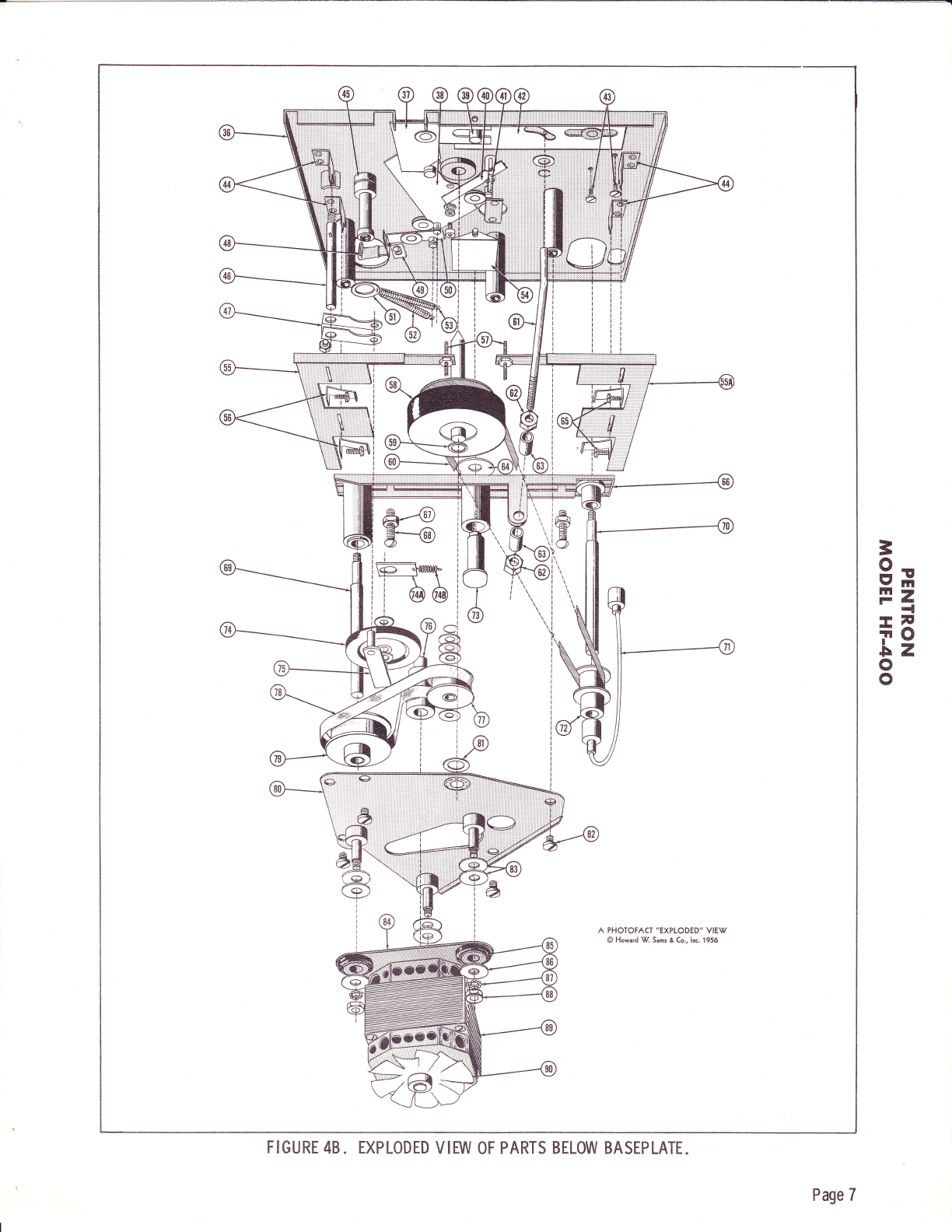
FUNCTIONS OF PRINCIPAL PARTS
Unimagic Control (5)-
This control has three positions:
1, rrP-R'r - Play And Record Position.
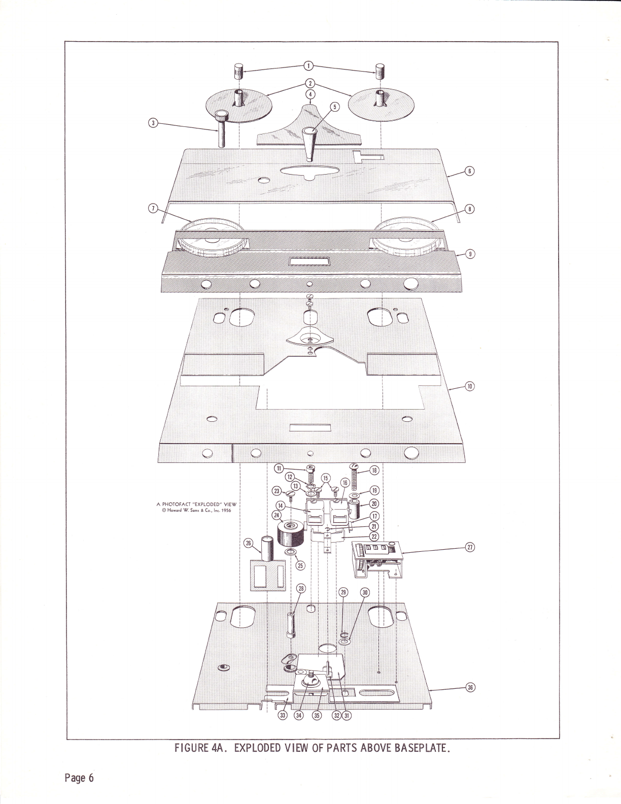
When the "Unimagic" control (5) is moved into
the trP-Rtr position. the piay-record control cam (3?)
is actuated by the shaft in the control. This pivoting
movementof cam (3?) allows the pressure roller slide
plate (38)tobe activated by the pressure roller spring
(53) which engages the pressure roller (24) with the
capstan (58) which in turn drives the tape at a constant
speed. The take-up adjusting lever (50) which is held
againsttheendof slide plate (38) by the take-up spring
(52) , is pivoted as the slide plate moves forward. This
causes the boot on take-up adjusting spring (aB) to
press against the equalizer bar (66) with just enough
pressure for the take-up belt (78) to become taut and
to rotate the take-up pulley (79) so as to wind tape on
the reel. This acts as a ciutch by allowing the belt to
slip due to the slower speed of the capstan. Also, by
the movement of slide plate (38) , pressure is removed
from the pressure finger lever (40), whichhasbeen
engaged with the pressure pad pivot pin on the pres-
sure pad carrier (32). which holds the pressure pads
away from the heads. When pressure is removed
from the pressure finger lever (40) the pressure pad
spring (41) pulls the pressure pad carrier (32) inward
causing pressure pads (22) to bear against the tape
and hold it in positive contact with the heads.
NOTE: Mechanical functions explained above pertain
to both Play and Record.
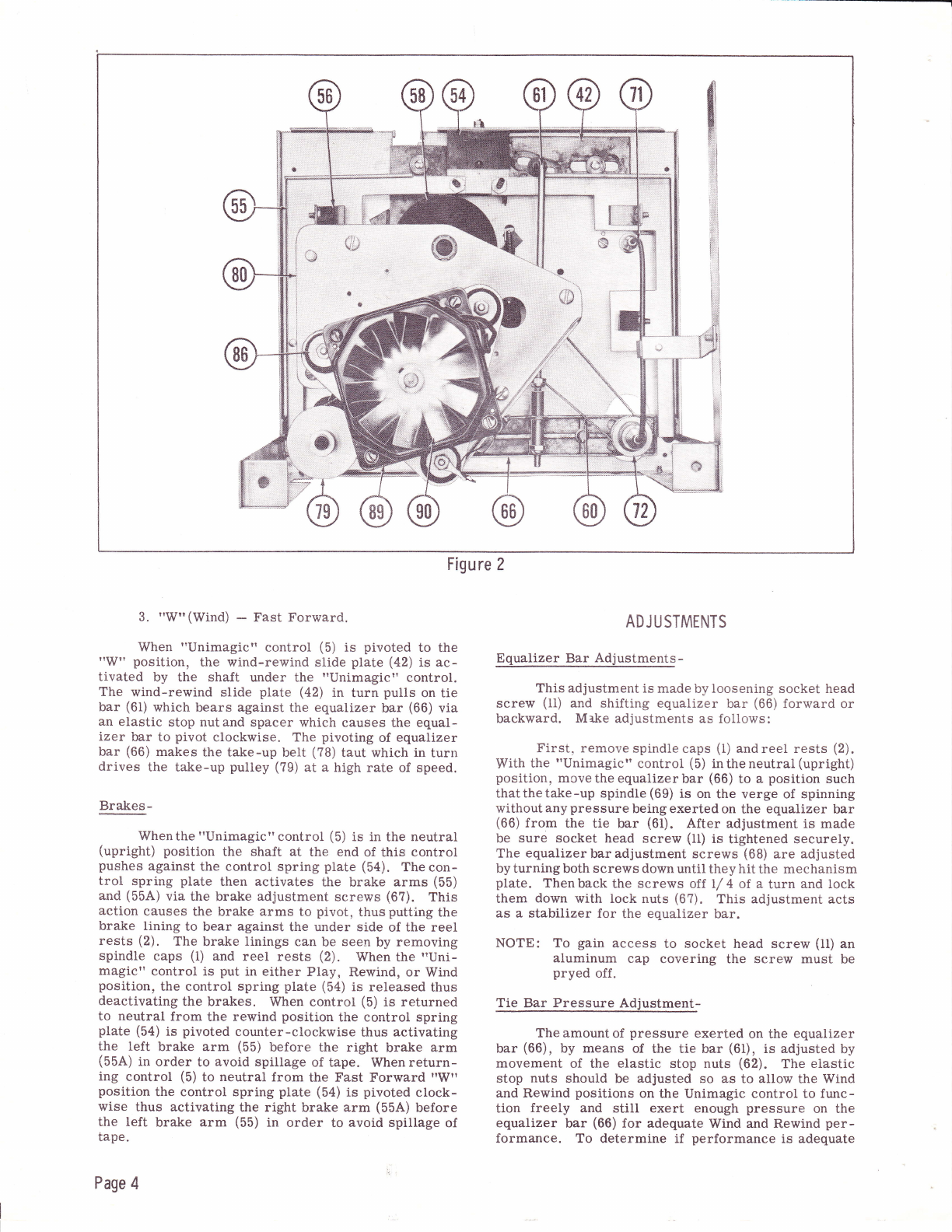
2. I'Rr' -- Rewind.
When the "Unimagict' control (5) is pivoted to
the "R" position the wind-rewind slide plate (42) is
activated by the sha-ft under the "Unimagic" control.
The wind-rewind slide plate (42) in turn pushes on the
tie bar (61) which bears against the equalizer bar (66)
via an elastic stop nut and spacer which causes the
equalizer bar (66) to pivot counter-clockwise. The
pivoting of the equalizer bar makes the feed belt (60)
taut which in turn drives the feed pulley (?2) at a high
rate of speed.
3
9*
Pz
-l
-il,
io
Lz
o
o
Page 3
!-l
; .:i
t.tt
ti;,;
;id
:.ni
({;x9i
l#Pi
fl
i1
il
i
Figure 2
3. "W"(Wind) - Fast Forward.
When "Unimagic" controt (5) is pivoted to the
"W" position, the wind-rewind slide plate (42) is ac-
tivated by the shaft under the "Unimagic?' control.
The wind-rewind slide plate (a2) in turn pulls on tie
bar (61) which bears against the equaiizer bar (66) via
an elastic stop nutand spacer which causes the equal-
izer bar to pivot clockwise. The pivoting of equalizer
bar (66) makes the take-up belt (78) taut which in turn
drives the take-up pulley (79) at a high rate of speed.
Brakes-
Whenthe "Unimagic'control (5) is in the neutral
(upright) position the shaft at the end of this control
pushes against the control spring plate (54). The con-
trol spring plate then activates the brake arms (55)
and (55A) via the brake adjustment screws (6?). This
action causes the brake arms to pivot, thus putting the
brake lining to bear against the under side of the reei
rests (2). The brake linings can be seen by removing
spindle caps (1) and reel rests (2). When thetrUni-
magic" control is put in either Play, Rewind, or Wind
position, the control spring plate (5a) is released thus
deactivating the brakes. When control (5) is returned
to neutral from the rewind position the control spring
plate (5a) is pivoted counter-clockwise thus activating
the left brake arm (55) before the right brake arm
(55A) in order to avoid spillage of tape. When return-
ing control (5) to neutral from the Fast Forward "W"
position the control spring plate (5a) is pivoted clock-
wise thus activating the right brake arm (55A) before
the left brake arm (55) in order to avoid spillage of
tape.
Page 4
ADJUSTMENTS
Equalizer Bar Adjustments -
This adjustment is made by loosening socket head
screw (11) anO shifting equallzer bar (66) forward or
backward. Mal<e adjustments as follows:
First. remove spindle caps (i) andreel rests (2).
With the "Unimagic" control (5) intheneutral(upright)
position, movethe equalizerbar (66) to a position such
thatthetake-up spindle (69) is on the verge of spinning
without any pressure being exerted on the equalizer bar
(66) from the tie bar (61). After adjustment is made
be sure socket head screw (11) is tightened securely.
The equalizer bar adjustment screws (68) are adjusted
by turning both screws down until they hit the mechanism
plate. Then back the screws of,f I/ 4 of a turn and lock
them down with lock nuts (67). This adjustment acts
as a stabilizer for the equalizer bar.
NOTE: To gain access to socket head screw (11) an
aluminum cap covering the screw must be
pryed off.
Tie Bar Pressure Adjustment-
The amount of pressure exerted on the equalizer
bar (66), by means of the tie bar (61), is adjusted by
movement of the elastic stop nuts (62). The elastic
stop nuts should be adjusted so as to allow the Wind
and Rewind positions on the Unimagic control to func-
tion freely and still exert enough pressure on the
equalizer bar (66) for adequate Wind and Rewind per-
formance. To determine if performance is adequate
Figure 33
9x
lll r
-G {
-F
io
ilz
o
o
test the Rewind with a full 7" reel onthefeedside. To
test for Wind piace full ?" reel on take-up side.
NOTE: The tie bar (61) must be readjusted whenever
equalizer bar (66) is readjusted.
Take-Up Adjustment-
This adjustment is accomplished by bending the
take-up adjusting spring (48). Bending the spring
closer to the equalizer bar (66) increases pressure on
the equalizer bar thus giving a stronger take-up. Bend-
ing the spring away from equalizer bar (66) gives a
weaker take-up. If bending spring (48) does not give
adequate adjustment, loosen the screw which mounts
the spring and move the spring in the proper direction
for optimum adjustment.
Brake Adjustment-
After equalizer bar adjustments have been made
the brakes are ready to be adjusted. First put a futl
5" reel of tape on the feed reel side. and an empty ?r'
reel on the take up side. Wind about L/ 4 of the tape
on to the ?" reel. While operating the Unimagic con-
trol from "Rewind" to 'T.[eutral", tighten the left brake
adjusting screw (5?) until the reels stop in about I
revolution without spiliing tape. Next, reverse the
procedurebyplacing the 5t! reel of tape on the take-up
side and the empty 7" reel on the feed side. Adjust
the right brake adjusting screw (5?) so that the reels
stopin "Fast Forward" to I'Neutraln in aboutl revolu-
tion. Next put a full 7r' reel of tape on the feed side
and an empty 7" reel on the take-up side. Run about
100' of tape on to the take-up reel and go directly into
"Rewindr'. When the take-up reel is almcst empty,
place the Unimagic control in tNeutralt!. The reels
should stop in about 3 or 4 revolutions without spilling
tape. Next, reverse the procedure by placing the fuIl
7" reel on the take-up side and rewind about 100' of
tape on the feed reel. Go directly into "Fast Forwardt'
until the feed reel is almost empty. Then place Uni-
magic control in 'Neutralf'. The reels should stop in
about 3 or 4 revolutions without spiiling tape. After
brakes are adjusted, check the take-up and rewind.
If the take-up or rewind has been affected, readjust.
If it is difficult to get adequate take-up, brakes may
have been adjusted too tight. Then readjust brakes to
rectify this condition.
Idler And Speed Change Adjustment-
Loosen the set screw and nut which secures idter
sha-ft (a6) to idler channel (47). Adjust position of idter
channel assembly (47) so that the fuil perimeter of idler
wheel (74) ridesonthe perimeter of motor puliey (?6).
While adjusting, position the height of idler shaft (46)
so that its ro11 pin will locate in the slot in the shaft
housing. Idler wheel (?4) must be adjusted so as not
to ride on the edge of the motor pulley.
Flexible Shaft Adjustment-
This adjustment is made by shifting the cable
clamp support bracket to a position so that a light
downward pressure is exerted of flexibie shaft {?1) so
as to keep it from whipping when machine is in r.Fast
Forward" or "Rewindt' position.
Play-Record Head Alignment-
To align the play-record head (14) a special head
alignment wrench is necessary. An alignment tape is
recommended for accurate alignment.
Page 5
FIGURE 4A. EXPLODED VIEW OF PARTS ABOVE BASEPLATE.
Page 6
3
gH
Ez
t-;
+6
tz
o
o
A PHOTOFACT'EXPLODED' VIE\r
@ Howard W. Sams & Co., lnc. 1956
FIGURE 48. EXPLODED VIEW OF PARTS BELOW BASEPLATE.
Page 7
To align head for azimuth, slip the alignment
wrench over the head can and rock head while tape is
playing until maximum output is obtained. This can
be readily heard because the high frequencynotes will
be apparent rather than the low mellow sounds. After
the head is aligned it must be secured by tightening
the back screw and sealing it with household cement.
If the height of the head has been disturbed, the center
Iineof the head and pole piece must be lined up so that
the pole piece is at the same level as the tape guides
and tape.
How To Replace A Pole Piece-
Remove the head assembly by loosening the two
mounting screws which hold down the head assembly.
The pole piece is then removed by inserting a non-
magnetic screw driver between the head can and the
pole piece and prying the pole piece loose by breaking
the glue joint. The new pole piece is then inserted
between the two laminations provided for each leg of
the pole piece and gluingit from the sides with house-
hold cement. The head assembly is then screwed into
place and the heads aligned.
LUBRICATION
Altlough this mechanism is prelubricated at the
factory, replacement of parts require that they be
lubricated in order to insure proper functioning. No
part need more than a slight film of grease where
grease is specified or one drop of oil where oil is
specified.
The following parts require greasing with fibre
grease or a similar compound:
1. Play-record cam (37).
2. Wind-rewind slide plate (42).
3. Control spring (54).
4. Control shaft (34), bottom end.
5. Slide plate assembly (38).
6. Pressure roller bearing (24) and (28).
?. Belt pulley (?7).
8. Tie bar (61), front end.
9. Idler wheel bearing (?4).
10. Clamp for flexible cable (71).
11. Record lock (26).
12. Equalizer bar pivot stud (66).
13. Take-up adjusting lever (50).
14. Pressure arm lever (40).
15. Pressure finger carrier assembly (32).
Thefollowingparts require oiling with 10 W lub-
ricating oil:
1. Feed spindle assembly (?0).
2. Take-up spindle assembly (69).
Page 8
3. Flywheel assembly (58).
CAUTION: Do not clean oilite bearings with cleaning
solvent. Oilite bearings are permanently
oiled, but in some instances where the
bearings appear dry a drop of oil will be
necessary.
CLEANING
The play-record head (14), erase head (16), cap-
stan (58), and pressure roller (24) are subject to an
accumulation of tape coating oxide which is worn off
the tape as it passes these parts. Clean these parts
with a soft cloth and alcohol after every ten hours of
running time,
TROUBLES AND PROBABLE REMEDIES
No Rewind-
l. Glazed idier wheel (?4). Rub off slickness
with a clean, dry, lint free cloth.
2. Faulty tie rod (61) adjustment. Adjust as
described under "Tie Bar Pressure Adjustmentt'.
3. Slippage of idler wheel (?4) against flywheel
or motor pulley. Clean idler wheel, flylvheel, and
motor pulley with alcohol. If idier wheel still slips,
replace.
4. Idler wheel (?4) not adjusted properly. Ad-
just as described under rTdler And Speed Change
Adjustment",
5. Binding feed reel spindle (?0). Loosen the
set screw in rewind pulley (?2). Clean bearing and
spindle surface and reinstall leaving .005 and play in
assembly.
6. Dragging brake linings. Brakes not properly
adjusted. Adjust brakes as described under "Brake
Adjustment".
?. Bent reei rest (2). Repiace reel rest.
8. Feed belt (60) loose or broken. Replace.
Flutter-
1. Motor pulley (?6) not concentric to motor shaft.
Replace motor and pulley assembly.
2. Excessivetake-up, Adjustasdescribedunder
"Take -Up Adjustmentt'.
3. Take-up belt (?8) not installedproperly. Re-
move and replace belt as shown on Exploded View,
4. Dirty flywheel bearings. Clean bearings and
flywheel shaft.
Wow-
l. Foreign matter on idler wheel (?4), motor
pulley(?6), flywheel(58), ortake-up pulley(?9). Clean
all wheels and pulleys with clean cloth and alcohol.
2. Defective idler wheel (?4). Replace.
3. Defective pressure roller (24). Replace.
I
4. Reel spindles (69) and (70) binding. Loosen Tape Spillage Or Insufficient Braking-
set screw on pulley, clean bearing and spindle sur-
face. Reinstall leaving .005 end play in assembly. l. Faulty brake adjustment. Adjust brakes as
described under "Brake Adjustment".
5. Brakes improperly adjusted. Adjust as de-
scribed under "Brake Adjustmentrr' 2. worn brake rinings. Replace linings and re-
No Wind (Fast Forward)- adjust brakes'
1. Binding take-up spindle (69). Loosen set 3. Worn-outorloosecontrol spring(54). Adjust
screw in take-uppulley(?9),-clean bearing and spindle or replace control spring.
surface and reinstaLl leaving ' 005 end.play in assembly 4. Excessive pray in equalizer bar (66). Readjust
2. Take-up belt (?8) loose, twisted, or broken. equalizer bar as described under t'Equalizer Bar Ad-
Replace belt. justmentst'.
MECHANICAL PARTS LIST
=
9x
tn-
-G{
|-
fio
Lz
o
o
Ref.
No. Part
No. Description Ref ,
No. Part
No. Description
I
2
3
4
5
6
I
I
I
l0
1l
L2
l3
t4
15
16
I7
r8
19
20
2r
22
23
24
25
26
27
2B
29
30
31
32
33
34
35
36
37
38
39
40
4l
42
43
44
45
46
47
7r4-A-276
?65 -B-12
714-A-474
7t4-A-413
6r3 -10896
61? -1134
616 -1144
943-A-11
611-80454
943-A-r0
?ll-A-345
611-11615
616-1144
?14-A-102
6r9 -144
964-A-124
611-60353
964-A-116
616-A-3169
498-A-2
7t4-A-47
619-146
619-A-24
7ll-A-34?
964-A-114
?11-B-134
964-A-268
7ll-A-592
711-C -13?
7ll-B-135
964 -A-23
7t4-A-472
?u-A-330
7r2-A-2r
?ll-B-133
611-60454
?lr-A-594
?14-A-16r
?14-A-336
711-A-343
Reel Spindle Cap
Reel Rest
Idler Shaft Knob
Head Cover Casting
Control Knob, Unimagic
Control Plate Casting
Volume Control Knob
On-Off -Tone Control Knob
Front Escutcheon
Top Cover Panel
#10-32 xL/2" Sckt. Hd.
Cap Screw
#10 Ext. Tooth Lockwasher
. lB? x . 437 x .031 Plain Washer
Record Head - Dual Track
#8-32 x L/ 4 B. H. M. S.
Erase Head - Dual Track
Tape Guide
#10-32 x I't Rd. Hd.
Mach. Screw
. i8? x . 437 x .031 Plain Washer
Dummy Stop
. 125 ttC' Washer
Pressure Pad & Plate Assy.
#6-32 x 3/ 16 B. H. M. s.
Capstan Pressure Roller
.250 x .500 x .010 Clock
St'1. Washer
Record Lock Button
Counter
Capstan Roller Shaft
. 188 "C" Ring
.190 x .3?5 x .010 Clock
St'l. Washer
Shiel.d Plate
Pressure Pad Carrier Assv.
Control Support
Control Assembly
Ball Retainer
Mechanism Plate
Play & Record Control Cam
Slide Plate Assy.
Control Shaft
Pressure Arm Lever
Pressure Pad Spring
Wind & Rewind Slide Plate
#6-32 x t/ 4 B. H. M. S.
Brake Support
Plate Stud
Idler Shaft
Idler Channel
48
49
50
51
52
53
54
55
55A
56
57
58
59
60
6l
62
63
64
65
66
6?
68
69
70
?l
12
?3
74
744
748
75
?6
77
?8
79
80
81
82
B3
84
85
86
8?
88
89
90
964-A-12i
?11-A-209
964-A-129
?r1-A-20?
?12-A-5
?12-A-6
742-A-23
?11-C -r39
?11-C-140
742-B-r
613 -81606
1t4-A-47r
8?l-23
899-A-2
?r4-B-3
6r5 -I124
714-A-182
?14-A-185
611-80454
964 -B-19
714-A-462
?r4-A-463
529-A-16
?14-A-135
?14-A-183
964-A-115
?1r-A-346
964-A-139
?14-A-167
714 -A-1?l
899-A-3
964 -A-91
?11-B-75
616-A-9209
611-10554
?11-A-341
?11-A-342
855-A-8
?11-A-341
6r? - 8l14
614 -8114
36?-B-6
?r7 -A-20
Take-Up Adjusting Spring
Take-Up Stop Plate
Take-Up Adj. Le'rer Assy.
Spring Ring
Take-Up Pressure Spring
Pressure Roller Spring
Control Spring
Left Brake Arm
Right Brake Arm
Brake Pivot Spring
#8-32 x li'Allen Hd. Cup Pt.
Set Screw
Capstan
Felt Washer
Feed Belt, ,3I2 x17.25
Tie Bar
#10-32 Elastic Stop Nut
Tie Bar Spacer
Equalizer Spacer
#8-32 x t/ 4 B. H. M. S.
Equalizer Bar & Bearing Assy.
Lock Nut
Equalizer Bar Adj. Screw
Take-Up Reel Spindle
Feed Reel Spindle
Flexible Shaft
Rewind Pull.ey
Equalizer Bar Pivot Stud
Idler Wheel
Idler Spring Clip
Idler Spring
Idler Bracket Sub Assy.
Motor Pulley
Belt Pulley
Take-Up Belt, . 312 x 12.625
Take-Up Pulley
Motor Support Plate
. 3?7 x 5/ B x .01 Clock
St'1. Washer
#10-32 x 5/ 16 B. H. M. S.
.2I8 x7/ 8 x l/32 Motor
Mtg. Washer
Motor Plate
Shock Mount
.2I8 x7/ B x / 32 Motor
Mtg. Washer
#8 Int. Tooth Lockwasher
#8-32 Hex. Nut
Motor
Motor Fan
Page 9
:z
o
11
hc
o
I!z
s
E
c
E
c\
c
+
!z
o
F
<l
G
€
c(L
F
c
o
o
ts
N
Y
o
AI c
o
h
ts
FCL
F
|f
cc
a
o+c
a
N
Y
6
+o-
-s
e
ts
d
G
o
6
nc
o
€
CL
F + o
ts
N
-
o
N
+
v
o
N
=t
cl
F
Fo
€
F
C'
x
€
=N-l F
o
I
(o
cu
ao
F
t4l
I
\,
(/t .O
n
zo\
o
FC
s-.
O.3
z4
(]:
E:
<ur
2>
(r
FL
vrI
_o
L,I
(or
r-
o
F
o
I
o-
ci
U
F
o
z.
u
vl
=
E.
U
I
F
o
at
vl
u
J
z,
J
z.
o
tr
a/,
o
rL
==
CL
-F
-))a-
2,. ,, -
!zvvA
<6@E
tsz.zo
r-;H
G==S
=o<)
fr e, ez.
dLr-
if,oaa-
ouuu>
<.Ee.e.=
!g===o
=VlU)(/)L
==Es=
* (r i-
F
=a
E i,!
ur
No-
=6
<6
fl2.
a;
UU
o- o-
v)o
<9
z.
6
u
e
u
o
z
F
ttl
6
u
e.
r:l
z
o
t<
2
OF:
.z
BO
ir(J
e.
o
F
o
=
o
@:
E<
>(J
=A
\9
o
N
6
tq
3@
fi Eo
o
r=t ,
=
o
F
=e?
=3
o5
do_
$z
U
E,=
>B
'<o
it
o- u.r
!z
€
\o
@
o
c_l
6,)
I
F
o
!:|fl
H5
€r
a
rrJ
e.
@
@
-)-
t<
IJ
lo-
a
e.
-O
;<
i;u
dL
LJ
k
z
G
u
\z
<9
tr3
.J
Eft
J<
Hs
dq
LJJ
rJ<
6>
o
d.>
luG
rE
=d
@
o
=
E<@
8rA
o :\S9zu
q_m
t
./4,
I
*fmrl
@
W€
@il6-
ers
.: \9
c1
v
a
sa
x@
F
@c>
6
F
o-
F
oO
=tr\
+Evt
=o€
REx
c)
9r:
od
=€
o<
-e
l-
.=
o-F-
=5
<o
N
3
==t
krE
e=e
>N
a<
<C\
o- -!o
@
^@l
q = €)*s
r vl
Page 10
=
ut
I
a
o
l-I
la
I
lrll
la
I
.L
L'
irt
J
o
&
l-
z
o
I
i,
Ov;
x!
oo
so
i8
tn E.c
e, ,c- E
noQ
ts b j
(J ET
<'b
L3r
{ o.!
(J€=
OL
il:I
x;i
l!eEo-
>.:
'6!
6E
ii
l'!t
>6
i.E
'Uo
oo
o.o
OU
lJ
.tt
e,
o
=
I
c.
(,
I
h
J
o
e,
F
(J
tlJ
Lr,t
la
Z=
9;
h
o.z
r-
4G
(J ,:
lnY
Et c,
aH
ad
ZJ
trt
h2
I,lE
-!o
I
'n;
l- lll
4co
4
6X5GT 6V6GT 6AQ5 I2AU76AQ5
u,
q
F
o
z
z
o
ts
J
J
ts
o
z
33 *n<
dfi &&
oo oo
o--
!9U.IOO
-icdcd:dd
=e!X!d
><<r.<<
B:
==
dd
.9o ,9o
HN HN
@e I @! |
$ ou)s om
DZD>29
d
uz
EF
d
JJ
-O;O
id-id_
oli toli I
gztrGzF
F
<C;
Or
ed
d4
NN
lt
MY
R cP N
6 a6 i
-Tft-Tr,:
a92B$S2B
<l{@<latD
6
<d
<z
Fiv
z<
ud
(J
-- ci Ei-- ci. J.
u:r o osl o o
octrodrd
@e!@!!
r oo I oo
azzazz
A;
Fp
3X.
tue
lt
I .9
$ dds dd
o o oo o o
add4dd
S::S:x
!r,E uzi.
o
z
F
d
rn
F
F
!
-i.q
n\)
nz
g< OcdaOd'a
o! 503 t
@ao6tnu)
E: {tqon<tro
q
r
F
o
z
z
g
{
!
IJ
5
!
!
z
Hd
oL
*i
or Ef,qEH+q+ 44qqqF*EEpp
li * * ir *ir * * ** * * *1il li
OUFF F{ E{F Er F FF F T F g OOOO
66S<O$$@S$$$;@=@666
i-e
oz
=5
66 @h
Nd =Nd6r6
fr3s=F=9F==p9ER:fr38*
r rss@+$@$v$s9N@t{ I I r I
U (J F F F F F. F{ E< F F T{ 9 F 9 (J O O O
;T>AAAAAAAqAA=A>DDDD
d
z
r
EE
-iG
oglm oo SS
oYo oo 6
JJJ S.iJ =.|
o@o -oo :o
oo- \mm r o 6;65
.l*J i"i.l X"i +++r
*** *** 3* ====
vvv vvv 9u €666
66
NN
@@
-.!d c
i=z
5=: 3aE636aaS3-E
EEBEEEEE$EEEEEesree
OOOU U(JOCJ OOOOGO =o oti g
fe
<L
9.p
=4
t,tt aAEEEEIE;;EEEE AAEa
5e
9u
U<
<a
66 6@
NN NN66
oo ^oooo
oo6r r6 :<6n xOOOO
OOOOaOO-OOoO ^Xoooo
AAAA=ddFdAdA=EJooAo
HftfrfiHfiA#ftHfiHHfr9frfrfifr
at
FiF
H^o
I5
ele ooooooooooooo
oooooooaooooo
{$o$$@$$s$6@c
'lg @ - 6O
OOn-Q:6O::66^OOOOOO
6@oooooooooo=oo6@oo
NN.. ...=.oNNG@
frt &@roo9=S9g59f39RFSR
OOUOOOU()OOOOO(JO(JOOC)
F
F
z
r
:
U
qd
oL
SE
G<
6d
F Fq*
W NN
s
i *s*
F FFd
9e
Op
3s
66:r
- NSKS
q! 'i' -i t !E
'? 55F{F
G r-;ii>>
od
=z
{p
4e
rj NN
tt
6@
NN
tt
AQ
E< E{
o
N
O
F<
>i
4y
oz
:5 N @666
9 NNNN
A OOOO
h FFFF
<t
!l
!l rad
dvz
&6E
8e3 I ^-66
=T FREil
otr E&&d
om aooco
5i
9E
u<
<e
n9
Nt 66H
@ NNZ
g >>>
!- 66@
t ssa
k dcc :L
p
.9 ..i
fi_.M
o!-
!o
E TOF
9iE
H ok
o:,1o
NYL
'a F.l o
U.t o
; Ppq
zi9
. R>
+:=
o o:
6ot
z
AO
ez
Fp
Ze
iir <
^d a
o
z
Foooo
6@@@66@
OOO6NNN
d
U$o==@6o
a l < NN6
{;
r-Y
tsz Jtroa^-*
O ()OO
U)
u
F
o
z
q
4
FFE<
?89 H
<<>x
q
faa=
ooE.9
o oe=
<<o0,
Et s6@r
U
F
o
z
u
4
Fr
Or:
r>Jl
n 3*
g
q
l
!
to
of
@o
>E
,|:
Li f @
ii: E.g d
.H* A*E
EE 35 s,
i ji 5t b
5:<:<E
o -, u- =
e!sfiii
F: dN o
Page ll
3
lr|
I
E
o
l-
F
o
6
I
ra
I
ta
ta
n
.L
(\,
u
llt
-
t!
tr
I
ut
u
=
f
z
lr|
J
tlt
ut
t!
-I
lL
&,
vt
J
6
tJ
e
tlt
v
ll|
r
vt
F
D
e.
l-
f
o
I
o
f
u,
lr|
=
e,
o
l!
(n
z
E
F
e
llt
=
o
g
e,
UI
=
e,
o
t!
vt
z
/,
F
c;
q)
.e
c)
.f,
'=
c)
.C
o
,t,
rt,
c)
c
tti
t/1
q
o
tg
=
AI
tt
q,
trtl
(g
(g
=
A
'u
o
3
C
.I-
tr
o
(,
v
tft
z
o
-
lr
&tn
-g!
go
rJh
nn
as
o
z
F
ln
n
J
rn
l-
&,
<
0
tn
l!
F
o
z
6
o.
F
o
€
'A
a
I
F
a
\t{ X q)
.osi
9=j
ncd
95bo
vFd
&trrE
rc!
>.o I
-cdOY
* T Efi
=
Iu
U
J
CL
LLJ
e.
nz.
=F
;3
e,
o
F
o-
llj
U
ul
d,
'_d
6z-
=3
z
oo
{r-
7e.
e{
trl o-
F
1
pq
n
E-
$
a2
L{F
';E
nf
z
9,2
F,
Ze,
rd<
Ao-
=
bo
'f.c g ,-
sOOii
c::;
E;; g
lrl
z
e,
o-
F
z
tlt
d.
d.
f
I
U>
IU
F
o
zt{
0)
i
ni
tJ-) L
J
JF
=?
o-
o
ts7
e.
u.r F
<: d'
-<l
o-l
ffc;
zz
a
aE
=s
6e
&-
F3 6A
aT
co 6a
an
l!
E
(,
o
U
lLl
V)
e.
o- c\t
tl,
v)
J
-: .d
VA
u)t':
r) o \-,
,!4 +r
U): Cd E
d'i o 5
'dUAF
NC)6'A
fri c\
J-1
.a
[t
o
z
o
z
UJ
=
ul
U
I
o.
uI
d
o
<z
(J u.r
Eo-
F
rnau)
o) o) ctJ
61 c\l 6t
6t cN 6l
22
3-
dz
at-
co co 1t{
z
&2
ts-
ZE,
trl <
Ao-
rl)uao
ttt
r(:ll)r()
Sl .tl <]t
60 66 CO
t,
o
z
t
o.
t
U
:
o
UJ
lL
<{3{$
ttl
co co 6.J
EE>
AAA
UJ
N
rn co c0 3{
f;-s
FZ, Hilf;
.n
ut
F
o
z
bo
#
o
tr
F
q)
o)
.'1 O)
n;
e
o
F
z
lr|
=
lll
rJ
J
4
IIJ
d.
C;
7z
E
-L cta
4
X
rrl
]rJ
I
o
oo
tL
o
TE
9<
:! lL
co
L()
a
6I
6:
-d
3z
cF
ae,
.;{ o
t-
co
I
o
t-
.= z-
OF
=t
o-
O
OJ
g\l
I
oo
'L
iu
E<
Io-
e
qJ
o
O
N
z
Oc;
trz
H
vr-
4e.
F<
l{ aL
o,
I
6l
$
6A
III
LJ
z
o
lLt
o-
=
U
II
V, $I
ca
d
o. M
t--
F: C!
E-t
F
o
t-
z
llt
=
llt
LJ
J
o-
U.J
e.
o
rZ
o
,*Eo-
oo
tZ-
o
-oF
Ld,
9<
-o-
-o
o7
g-
LF
ad.
6<
o
d
.-LOF
<d.
CL
c.
OO
2z
o
r!
o<
Io-
6:
d-
tr{F
ie,
^<
trl o-
A
6A
6a
C\l
ro
6a
()
z
d.
ti
U,l
al.
(\
{.
rl
a.l, H1
dra)
rl{
b3
Fo
lr)
E-^
ro (dl)
O<
Eq
=G)
fr* d
Ft
.n
llJ
F
o
z
o
z
llJ
=
tlt
U
J
e
lft
e
o
vz
ets
-e o-
Ba be
() tr:
i555:5IH5S:XHi5
HhhhhHhEhHHHhhE
Ee
ts-
Zd,
ra{
^.G
o
A
tr
e,
tr
;# =$
.n
=
oss
HsHssgREgscxsHF
Fi a o = c\l CO ltt rf) (() t- o o, o I 61 60
=Atc\r61 c\I c\tN6tg\161 6lcACOcAcO
Edfi8dtrfifififidfiefrfr
ln
ut
F
o
z
cl
z
ll!
=
ul
U
5
A.
lrt
c,
o
uz
CF
A
b0
o
EvEFaSsEBxPs4vEEx
E35*.FSFFEEESgNN=
ttltttttttlttttt
a(Aaaau)aa(naaaaaav)
F E-{ F t-{ E-r E. F F F{ E-r F E< F{ F E{ E-{
tr m tq tr cq tr E tr pq tr !0 Fq pq rq pQ pq
A;
&1
tsp
zc,
iii <
P* a'
o
z-
tr
u
tr
=
v,
=
o$uHIxHxrgHg$gHHg
Ei 6o.il 'o (o tr- @ ot 9 = E I : I I 5 =
fitrfifiddEddddEdEEd
Page 12

Popular Cassette Player manuals by other brands

Optimus STEREO MATE SCP-81 owner's manual

Optimus

Optimus STEREO MATE SCP-81 owner's manual

Aiwa RM-P300 Service manual

Aiwa

Aiwa RM-P300 Service manual

Philips AQ 6587/01S Instructions for use

Philips

Philips AQ 6587/01S Instructions for use

Panasonic RQ-E30V operating instructions

Panasonic

Panasonic RQ-E30V operating instructions

Honeywell DELTA21 Operator's manual

Honeywell

Honeywell DELTA21 Operator's manual

Sony WM-EX190 - Walkman Cassette Player operating instructions

Sony

Sony WM-EX190 - Walkman Cassette Player operating instructions

Teac AD-800 owner's manual

Teac

Teac AD-800 owner's manual

Philips AW 7550 Instructions for use

Philips

Philips AW 7550 Instructions for use

Philips AW7304 user manual

Philips

Philips AW7304 user manual

Sony TC-D5M manual

Sony

Sony TC-D5M manual

Pioneer CT-W910R operating instructions

Pioneer

Pioneer CT-W910R operating instructions

Marantz CR2020 user guide

Marantz

Marantz CR2020 user guide

Philips AQ6542 Manual do usuário

Philips

Philips AQ6542 Manual do usuário

Aiwa TP-VS500 operating instructions

Aiwa

Aiwa TP-VS500 operating instructions

Philips AW 7760 Instructions for use

Philips

Philips AW 7760 Instructions for use

Sony WM-FX521 - Walkman operating instructions

Sony

Sony WM-FX521 - Walkman operating instructions

Dual C 808 operating instructions

Dual

Dual C 808 operating instructions

Philips AZ 8110 user manual

Philips

Philips AZ 8110 user manual

manuals.online logo
manuals.online logoBrands
  • About & Mission
  • Contact us
  • Privacy Policy
  • Terms and Conditions

Copyright 2025 Manuals.Online. All Rights Reserved.