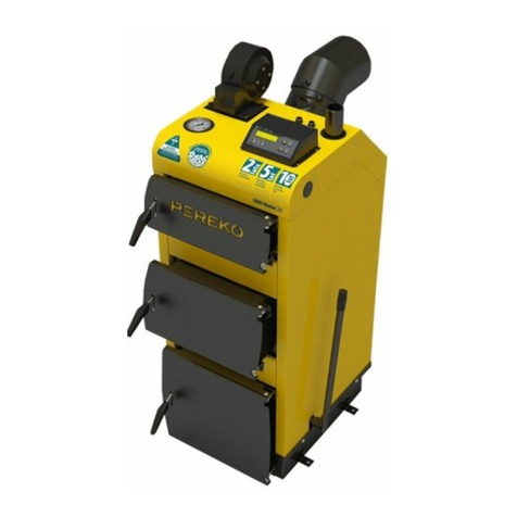
Per-Eko KSR Beta Pelet 20 User manual

Operation and maintenance manual for
KSR Beta Pelet
series boilers with feeders

TABLE OF CONTENTS
1. INTRODUCTION............................................3
1.1. Obligations of the user and guidelines concerning safety . . . . .3
1.2. Selection of correct power of the boiler....................3
2. TECHNICAL DESCRIPTION ....................................4
2.1. Intendeduse..........................................4
2.2. Designdescription.....................................4
2.3. Boilerdesigndiagram..................................6
2.4. Operation and technical parameters. . . . . . . . . . . . . . . . . . . . . . .7
2.5. Fuel..................................................8
2.6. Equipment............................................8
3. BEFORE START-UP..........................................8
3.1. Boilerroom...........................................8
3.2. Connectiontochimney.................................9
3.3. Connection of central heating
and domestic hot water system........................ 10
3.4. Connection of the boiler to electrical system..............11
3.5. Filling the system with water . . . . . . . . . . . . . . . . . . . . . . . . . . 12
4. SERVICE MANUAL ........................................13
4.1. Safe operating conditions . . . . . . . . . . . . . . . . . . . . . . . . . . . . . 13
4.2. Before rst ringup..................................13
4.3. Firing up in the in KSR Beta series boilers . . . . . . . . . . . . . . . . 14
4.4. Refueling........................................... 15
4.5. Stopofboileroperation...............................15
4.6. Adjustment of hopper chute . . . . . . . . . . . . . . . . . . . . . . . . . . . 15
4.7. Cleaning and maintenance . . . . . . . . . . . . . . . . . . . . . . . . . . . . 16
4.8. Emergency stop of boiler operation . . . . . . . . . . . . . . . . . . . . . 16
5. BOILER OPERATION DISTURBANCES
– BEFORE CALLINGTHE SERVICE............................... 17
6. WARRANTYTERMS AND CONDITIONS . . . . . . . . . . . . . . . . . . . . . . . 18
Thank you for purchasing PEREKO heating boiler. This documen-
tation applies to the KSR Beta Pelet series boilers with fuel feeder
- wood pellet. The manual contains all necessary information and
recommendations concerning operation.
Please carefully read this document before start-up of the
boiler. Observance of the guidelines contained in the manual will
ensure safety and prevent against misuse of the equipment and
its faulty operation.
Manual for the controller, which should be read and understood,
is enclosed in the set of documents for the boiler supported by
electronics. Documentation and manuals should be kept and
stored in a way allowing using them also during servicing of the
equipment.

3
PageOperation and maintenance manual for the KSR Beta Pelet series boilers with feeders. The producer reserves the right to introduce technical modifications.
1. INTRODUCTION
1.1. Obligations of the user and guidelines concerning safety
To assure operational safety and maintain optimum operation
of the equipment:
• read the manual of the boiler, controller, feeder and observe
their guidelines,
• the manual should be kept and stored in a safe place in the
boiler room allowing using it during any moment of boiler
operation,
• ensure that it is never operated by children or persons who
have not read the contents of the manual and adults with
disabilities preventing them from the safe operation,
• the system should be made in compliance with the applica-
ble regulations and in accordance with the rules and recom-
mendations contained in the manual,
• before setting and connecting the boiler check whether all
components are in good working order and whether the
boiler has a complete equipment for servicing and cleaning,
• the boiler should be cleaned on regular basis, at least once
per week, removing a layer of deposited soot and ash, which
reduces the eciency of the boiler,
• ensure continuous access to the equipment,
• avoid exceeding water temperature in boiler over 95°C,
• maintain operating pressure not exceeding 1.5 bar.
NOTE! Boiler installation in accordance with the applicable
standards and regulations and rst start-up should be car-
ried out by a qualied installer.
1.2. Selection of correct power of the boiler
Nominal power of purchased boiler (that is maximum ther-
mal eciency, which can be reached during continuous use
maintaining the eciency declared by the producer) should be
selected in a way corresponding the real demand for thermal
energy even in case of occurrence of very low temperatures.
Do not purchase boiler with power higher than this planned
in the design. Selecting boiler with too high power will result in
higher fuel consumption and lack of full control over the com-
bustion process and therefore higher operation costs, while too
small boiler will not ensure sucient power necessary to heat
up the building.
Approximate boiler power can be calculated using a pow-
er calculator on our website www.pereko.pl Furthermore, you
should also consider: thickness of walls and insulation, the
thermal permeability of rst x joinery (including: tightness of
windows and doors, type of window panels used) and climatic
zone, where the heated building is located.

4Page Operation and maintenance manual for the KSR Beta Pelet series boilers with feeders. The producer reserves the right to introduce technical modifications.
2. TECHNICAL DESCRIPTION
2.1. Intended use
Steel heating boilers KSR BETA PELET are intended for instal-
lation in the central heating water systems in single-family
houses, garages, maintenance rooms etc. These boilers belong
to a group of low-temperature boilers and are not subject to
registration in the regional Oce of Technical Inspection. They
are intended for operation in water distribution piping of the
gravity hot-water systems or in open systems with forced circu-
lation, which are equipped with protections in compliance with
the requirements PN-91/B-02413 applying to the protections
of the open water heating system (considering the Regulation
of the Minister of Infrastructure, Journal of Laws of 2009 no. 5
item 461).
2.2. Design description
2.2.1. The set includes
• Boiler body (on pallet)
• Charging hopper (on pallet)
• Burner with feeder (packed in cardboard box)
2.2.2. Water casing
KSR BETA PELET heating boilers are made of steel sheet P265GH
intended for production of the pressure equipment operating in
the elevated temperatures. Heat exchanger sheets are welded
from both sides and body sheets are reinforced with supports.
Location of convection ducts allows cleaning through the upper
doors. Ash and soot are removed through bottom doors. Design
solution, that is the use of three-draught design of the furnace,
ensures ecient reception of heat.
2.2.3. Doors
The boiler is equipped with top doors intended for cleaning,
central inspection doors and bottom doors, with pellet burner
and they are intended for removal of ash formed during the
combustion process.
2.2.4. Water jacket
The water jacket is a space lled with heating medium - water.
The structure is made of steel sheet P265GH for pressure equip-
ment intended for operation at elevated temperatures.
2.2.5. Thermal insulation panels
Insulation panels xed on the surface of the water casing lim-
its heat losses to the environment. They are made of aesthetic
panels made of a zinc-plated metal sheet, painted with powder
paint ensuring high anti-corrosion protection. The modules are
lined with a mineral wool from the inside, which is used as an
insulation material.

5
PageOperation and maintenance manual for the KSR Beta Pelet series boilers with feeders. The producer reserves the right to introduce technical modifications.
2.2.6. Electronic controller
Microprocessor controller, installed in upper front part of the
boiler allows programming temperature of boiler operation and
programming changes of temperature of its operation at any
time.The controller is also responsible for the so-called blowing
of the furnace chamber.The controller is also equipped with op-
eration control sensor and sensor of emergency boiler shutdown
after exceeding water temperature 95°C. Detailed information
you will nd in the“User’s manual of microprocessor tempera-
ture controller”, enclosed in the boiler documentation.
2.2.7. Set of feeder with burner
The unit consists of two modules: burner driven by the mo-
toreducer, which is installed in the bottom doors or on the side
of the boiler and pellet feeding tube with drive and transport
screw. Its task is to take the fuel from the container and feed it
automatically to burner part. Unit design allows quick assem-
bling and disassembling.
2.2.8. Water connections
Water connections are intended for connection of boiler to the
central heating system. Size of supply and return connection
- G 1 1/2”internal thread.
2.2.9. Flue with a damper
Flue with rotary ue gas damper is an integral part of the boiler,
which discharges ue gas towards the chimney ue.
2.2.10. Flue gas swirlers
Flue gas swirlers are located inside the convection ducts to swirl
ue gas stream, what has an inuence on the increase of e-
ciency and the boiler power. The swirlers should be removed in
case of weak chimney draught.

6Page Operation and maintenance manual for the KSR Beta Pelet series boilers with feeders. The producer reserves the right to introduce technical modifications.
2.3. Boiler design diagram
1. Boiler body;
2. Pellet-red burner
3. Feeding unit
4. Charging hopper
5. Electronic controller
6. Ash-pan doors
7. Flue
1
5 7
2
6
4
3

7
PageOperation and maintenance manual for the KSR Beta Pelet series boilers with feeders. The producer reserves the right to introduce technical modifications.
2.4. Operation and technical parameters
S S1 L
L1
L2
H3
H2
H1
H
Parameter Unit Model
16 20 24 28
Dimensions
D [mm] ∅159 ∅180
E [mm] 348 ×198 348 ×248
L1 [mm] 110
L2 [mm] 800
L [mm] 490 520 590
H [mm] 1285 1390 1450 1560
H1 [mm] 1070 1160 1220 1330
H2 [mm] 175
H3 [mm] 1250
S [mm] 490 550
S1 [mm] 610
Primary fuel — wood pellet
Thermal power range* [kW] 4.8 – 16 6 – 20 7.2 - 24 8.4 – 28
Area of heated rooms** [m2] do 290 do 364 do 436 do 509
Heated rooms volume [m3] do 725 do 909 do 1090 do 1273
Charging capacity of container [dm3] 300
Boiler water capacity [dm3] 56 63 73 89
Heat exchanger material — steel P265GH [PN-EN 10028]; thickness 5 and 6 mm
Maximum operating pressure [bar] 1,5
Wymagany min. ciąg kominowy*** [Pa] 20 25
Supply / Power [V/W] 230 / 50
Boiler weight without water [kg] 268 304 342 397
Energy-eciency rating — A+
5 CLASS acc. to PN EN 303-5:2012 — yes
The boiler meets the ECODESIGN — yes no yes
The boiler meets the requirements of the
REGULATION OFTHE MINISTER OF DEVELOPMENT AND
FINANCE of 1 August 2017
yes
Warranty —
10-year warranty for tightness of welds
6 years warranty for tightness of heat exchanger
2 years warranty for components
*maximum water temperature in the boiler – 95°C; **for rooms height 2.5 m and insulation with styrofoam 15 cm (q = 55 W/m2); ***PN-EN 12809, PN-EN 303-5:2002;

8Page Operation and maintenance manual for the KSR Beta Pelet series boilers with feeders. The producer reserves the right to introduce technical modifications.
2.5. Fuel
Wood pellet is a primary fuel used in the KSR Beta Pelet: PN-EN
ISO 17225-2:2014 – class A1. Fuel used for combustion in the
pellet-red boiler should have sucient caloric value > 17 MJ/
kg, be dried (moisture content ~ 10%) and have size recom-
mendedbythe producer (6±1mm and8 ±1mm). Useof moist
or too large fuel can lead to locking in the feeder and serious
failure of the boiler. Ash content should be lower than 0.5%,
the unfavourable chemical composition of the fuel can result in
sintering and formation of large amounts of dust and soot and
increased fuel consumption.Times given in the table on page 14
apply only to operation with suitable fuel.
2.6. Equipment
Prior to the boiler setting you should check the presence of addi-
tional tools and operation of the instrumentation.The complete
set should include: burner with a feeding system, fuel container,
electronic controller, brush, hook, ash shovel, drain cock, fuel
swirlers.
3. BEFORE START-UP
3.1. Boiler room
• It should be a separate room with height not lower than 2.2
m in the newly constructed building (in the already existing
buildings the allowable height equals to 1.9 m).
• It should have articial lighting installed and have natural
lighting as far as practicable.
• It should have gravity ventilation in good working order,
including:
1. air-supply duct in the external wall with cross-section
not lower than 50% of chimney cross-sectional area on
height maximum 1 m over the ooring or not lower than
200 cm2for boilers with power up to 25 kW or 400 cm2
for boilers over 25 kW,
2. 2. separate air-exhaust duct on the internal wall with
cross-section not lower than 140x140 mm with an out-
let located under the boiler-room roof near the chimney.
NOTE! It is forbidden to use mechanical exhaust ventilation
in the room where the boiler was installed.
• Floor gully and oor with 1% slope towards the outlet
should be planned in the central part of the room.
• Flooring and walls in the whole room should be made of
non-combustible materials.
• The doors to the boiler room should open outwards.
3.1.1. Method for boiler setting
The boiler requires non-ammable ooring, in form of a foun-
dation, but it is allowed to place it on non-ammable wall base
with height not lower than 50 mm. The boiler should be placed
in a way ensuring free access to the equipment, allowing its
cleaning and maintenance. Therefore, while setting the boiler
it is recommended to maintain minimum distances from the
individual walls:
• distance from the front of the boiler to opposite boiler room
wall should not be smaller than 2 m,
• the distance of boiler side from the wall of the boiler room
should be lower than 1 m,

9
PageOperation and maintenance manual for the KSR Beta Pelet series boilers with feeders. The producer reserves the right to introduce technical modifications.
• the distance of rear part of the boiler from the wall of the
boiler room should be equal to at least length of the connec-
tion, that is 0.25 m.
3.2. Connection to chimney
1. It is necessary to prepare stand-alone, tight chimney ue,
which will be used for ue gas from the boiler.
2. The ue should be placed at least 1.5 m over the roof ridge
to avoid the occurrence of backdraught. The intersection of
the ue should be appropriately selected for the boiler pow-
er and height of the chimney. Approximate calculations of
chimney height and intersection can be carried out using
a chimney intersection calculator available on the website
www.pereko.pl Regardless of the results of the calculations
the minimum intersection of masonry chimney should not
be lower than 14 x 14 cm!The intersection of non-insulated
steel chimneys should be bigger by 20% and the chimneys
made from steel pipes should be about 15-20% higher than
brick chimneys.
3. Check condition of the chimney (preferably by a chimney
sweep) before connecting the boiler to the chimney and
check whether the chimney is free from connections of the
heating elements.
4. The boiler should be connected with chimney using a con-
nector. It is not recommended to use the connection at a
straight angle because it will cause a loss in the chimney
draught. Flue with chimney should be joined with a connec-
tor made of steel sheet of thickness 3 mm (to be purchased
from the boiler producer). We put it on the outlet from the
ue, x on the chimney and seal with high-temperature
silicone. The connector should be directed slightly upwards
from 5° to 20°. If boiler ue will have a length over 400
mm then it is recommended to insulate it with a thermal
insulation.
NOTE! Boilers should be installed in compliance with the
applicable Regulation of the Minister of Infrastructure
(Journal of Laws of 2002 no. 75 item 690 and Journal of
Laws of 2009 no. 56 item 461.) In addition, it is recom-
mended to use chimney liner resistant to corrosion: chem-
ical, pitting, intercrystalline and surface.

10 Page Operation and maintenance manual for the KSR Beta Pelet series boilers with feeders. The producer reserves the right to introduce technical modifications.
3.3. Connection of central heating and domestic hot water system
3.3.1. Open water installations
KSR Beta Pelet boilers are intended for feeding water distribu-
tion piping in the open central heating systems with gravity or
forced circulation of water.The system, where the boiler will be
operated, should meet the requirements of the Polish Standard
PN-91/B-02414 Heating and district heating - Protection of
open water heating installations - Requirements.
Equalizing tank
Non-return ball valve
Non-return valve
Central heating pump
Pump
Boiler
Heaters
Storage-type
water heater
for hot water
Exemplary diagram of the open central heating system with four-way valve and hot water heater

11
PageOperation and maintenance manual for the KSR Beta Pelet series boilers with feeders. The producer reserves the right to introduce technical modifications.
3.3.2. Closed installations water
distribution systems
KSR BETA PELET heating boilers with automatic fuel charging
with nominal power up to 300 kW can be used in closed water
heating systems provided that:
1. the system has been equipped with membrane expansion
vessel;
2. a device intended for removal of heat excess, that is
two-function cooling valve REGULUS DBV-1, was installed
3. the safety valve 1.5 bar was installed.
NOTE! Correct selection of protections and suitable expan-
sion diaphragm vessel having inuence on safety level of
the system and the boiler. The above equipment should
be rigorously inspected minimum twice per year. The rst
inspection should be carried out during seasonal start-up
of the boiler with the water distribution system.
3.3.3. Four-way valve
Design of the heating system should take into account protec-
tion of the boiler against the return of too cold water from the
system. It is recommended to use four-way mixing valve what
allows the increasing temperature of water returning to the
boiler.
Four-way valve mixes hot water from the supply with cooler
water returning from the heating cycle and therefore:
• protects the boiler against low-temperature corrosion and
premature wear,
• improves the eciency of heating of tap water in the DHW
storage tank,
• allows smooth adjustment of the temperature of the heating
water with respect to the needs of the heating system,
• improves the eciency of operation of the whole system.
Designing of the correct diagram of the system for the house
and its execution should be entrusted to a person with appro-
priate qualications. Central heating systems may dier and
therefore it is necessary to stick to the guidelines included in the
central heating design. Below you will nd an exemplary con-
nection diagram of the boiler to the central heating and domes-
tic hot water system in the open installation with gravitational
or forced water circulation.
3.4. Connection of the boiler to electrical system
Boiler room should be equipped with electrical system with
rated voltage 230/50Hz in compliance with the applicable reg-
ulations. The system should be terminated with plug-in socket
equipped with protective conductor contact with connected
protective conductor terminal PE to protect against electric
shock.

12 Page Operation and maintenance manual for the KSR Beta Pelet series boilers with feeders. The producer reserves the right to introduce technical modifications.
3.5. Filling the system with water
3.5.1. Filling the boiler with water
before rst start-up
1. Flush heating system and boiler before lling it with water to
remove all contaminations.
2. Fill the system with water through the drain cock using the
exible hose. Water intended for feeding the heating boil-
er should meet the requirements of the PN-93/C-04607
standard. Quality of water lling the central heating system
inuences its durability therefore this water should be free
from the contaminations, oil and aggressive chemical sub-
stances.Waterhardnessshould notexceed2°tn (1°tn= 0.71
mval/l).Too hard water causes deposition of sediment in the
boiler and heating system what decreases eciency and
may damage the boiler.
3. Water relling process in the system should be stopped
when the system is full. In such case the water will ow out
from the signalling pipe of the expansion vessel, which is
located at the highest point of the system. Additional mea-
suring instrument – pressure gauge, will indicate approx.
0.8-1.2 bar. Relling should take several seconds to make
sure that the water ows down from the vessel.
4. Close boiler drain cock and disconnect exible hose from the
boiler when the system is lled.
3.5.2. Relling system with water
Heating system with open container allows direct contact of
heating water with the air what results in evaporation and ne-
cessity to rell it.
NOTE! It is forbidden to add cold water to the hot system.
Adding water to hot components of the boiler may dam-
age it and is synonymous with loss of warranty.
The system can be relled with water only when the boiler is
cold. Firing up should be restarted after lling the system.
3.5.3. Draining water from the system
It is not recommended to drain the water from the system after
the heating season because it increases the risk of occurrence
of the corrosion and formation of boiler scale. The exception
is a time needed to carry out necessary repair and long-term
standstills of the boiler during strong frosts. In the latter case it is
recommended todrain thewaterfromthe systemtoavoidfreez-
ing and therefore damages and relling it when the frost is over.

13
PageOperation and maintenance manual for the KSR Beta Pelet series boilers with feeders. The producer reserves the right to introduce technical modifications.
4. SERVICE MANUAL
4.1. Safe operating conditions
To maintain safe operating conditions for the boiler you should:
• Execute heating system correctly in compliance with the
requirements of the standards: PN 91/B-02413, applying to
the protection of open water heating installations, consider-
ingthe RegulationoftheMinisterofInfrastructure,Journalof
Laws of 2009, no. 56, item 461.
• Fill the system with water correctly. Do not rell the system
with cold water during operation of the hot boiler.
• It is forbidden to operate the boiler if the water level in the
system is below the level indicated in the central heating
system user manual.
• Never use ammable liquids, e.g. petrol, for ring up.
• Do not extinguish the re in the furnace by pouring it with
water.
• Use suitable equipment and protective clothing (gloves,
goggles, head protection, shoes) during work with the boiler
and take special care during servicing of non-insulated com-
ponents (e.g. doors), which may heat up to high tempera-
tures resulting in risk of burn injuries.
• Do not stay on the side of the boiler during the opening of
the doors and pay attention to ames.
• Take care of cleanness in the boiler room, ensure proper
ventilation and remove corrosive and ammable materials
located nearby.
• The boiler should be cleaned only when it does not work.
• Use mobile lamps supplied with a voltage lower than 24V
during works connected with servicing of the boiler.
• Take care of the good condition of the boiler and hydraulic
system.
• Take care of boiler cleanness.
4.2. Before rst ring up
Before the rst start-up, please check:
1. The correctness of installation and connection to electrical
system:
a. the actuator of the four-way valve (if any),
b. central heating pump, domestic hot water pump, oor
pump (if any),
c. the sensor in the boiler,
d. fan,
e. feeder.
2. Heating system:
a. its tightness, whether there are no leaks of water from
the boiler or system,
b. whether the water is not frozen in the conductors and
expansion vessel,
c. whether water level and its pressure are correct and
sucient (pressure gauge depending on the height of
the building should indicate from 0.8 to 1.2 bar). If the
pressure is too low, you should add water by pouring it
to the cold boiler.
3. Cleaning hole, which should be tight.
4. The correctness of boiler connection to the chimney.
5. Carry out measurements of chimney draught.

14 Page Operation and maintenance manual for the KSR Beta Pelet series boilers with feeders. The producer reserves the right to introduce technical modifications.
4.3. Firing up in the in KSR Beta series boilers
1. Fill the fuel container with suitable fuel (wood pellet).
2. Switch on the controller (see Controller User’s Manual) and
switch to manual operating mode.
3. Check operation of the individual equipment: operation of
the fan, feeder, activation of the central heating pump, do-
mestic hot water pump and a oor pump.
4. Turn othe fan. In manual mode the feeder starts feeding
the fuel for approx. 2-3 min. Wait until pellet starts falling
down in the exible hose of the feeder.
5. Set feeder on the electronic controller to “automatic mode”
after feeding the fuel (see Controller User’s Manual).
6. Set required parameters (boiler operation time, feeding
time, break in fuel feeding and blowing speed) after 10 min-
utes in accordance with specied values given in the user’s
manual for controller and feeder.
NOTE! Doors with burner should be tightly closed during
automatic operation of the boiler.
NOTE! The temperature on the boiler should not be set be-
low 57°C! It increases a risk of occurrence of a “dew point”
what considerably low-temperature corrosion in the heat
exchanger. Maintaining a temperature of feeding water
below 57°C with simultaneous use of incorrect solid fuels
leads to accelerated wear and tear of the boiler and de-
creases its eciency.
Whole combustion process will be controlled by the con-
troller when the boiler is red up (see Controller User’s Manual),
maintaining the set temperature of water in the boiler and tak-
ing into account building demand for heat.
4.3.1. Approximate output parameters
of the controller
The controller is pre-congured, but its output parameters are
changed, depending on fuel used (pellet) and may require indi-
vidual adjustment. They should be adjusted depending on heat
demand,type and quality (caloricvalue)ofpellet ordepending
on the development of the heating system. Selecting correct pa-
rameters ensures economical combustion of fuel.

15
PageOperation and maintenance manual for the KSR Beta Pelet series boilers with feeders. The producer reserves the right to introduce technical modifications.
4.4. Refueling
The container should be refuelled regularly to maintain contin-
uous operation of the boiler. If there is no fuel, the controller will
shutdown whole system and will signal lack of the fuel.
NOTE: Make sure that there are no contaminants, which
can lock operation of the feeder (debris, rocks, parts of
wood metal).
4.5. Stop of boiler operation
Switch to shutdown mode, where the controller stops the feed-
er and executes cyclic blowing to post-combust fuel residues.
When fuel brightness decreases the controller switches to
STANDSTILL mode and waits for the signal to start operation.
4.6. Adjustment of hopper chute
Adjustment of hopper chute allows directing feeding pipe to-
wards the burner. Loosen the nuts for this purpose (item 1) and
thendirectchuteto thegivenside (right orleft). Aftersettingthe
chute it should be re-tightened.
1. Wing nut
2. M8 screw
3. Cleaning hole

16 Page Operation and maintenance manual for the KSR Beta Pelet series boilers with feeders. The producer reserves the right to introduce technical modifications.
4.7. Cleaning and maintenance
Maintaining cleanness of the boiler is a necessary condition for
its eective, trouble-free operation. Even small layer of deposit
will cause a decrease of heat transfer from ue gas and reduces
boiler eciency as a result.The accumulated deposit can be also
a reason for boiler damage.
Therefore, the boiler should be regularly and precisely cleaned at
least once a week. Remove soot from the combustion chamber
and vertical smoke tubes using wire brush after extinguishing
andcooling downof theboiler.Removesootthroughside clean-
ing holes once a month.
4.8. Emergency stop of boiler operation
The boiler should be stopped always in case of:
1. water leakage from the boiler,
2. temperature increase over 90°C,
3. the necessity to rell evaporated water in the system and
heaters.
To stop operation of the boiler you should carry out operations
listed in “Stop of boiler operation”. If it is necessary to stop the
boiler quicker you should take out heat from igniter using a met-
al shovel to a metal container, remove heat from the boiler-room
and extinguish it with water there.
NOTE! Do not extinguish glowing fuel with water in the
boiler room!

17
PageOperation and maintenance manual for the KSR Beta Pelet series boilers with feeders. The producer reserves the right to introduce technical modifications.
5. BOILER OPERATION DISTURBANCES
–BEFORE CALLING THE SERVICE
The customer will bear the costs of travel and work of the sere technician in case of the unjustied calling of producer’s service.There-
fore, before you call the producer’s service please read the section concerning the most often occurring disturbances in boiler operation
and methods of dealing with them.
Symptom Cause Repair
Smoking outwards
insucient chimney draught remove leaks in chimney, ue or boiler doors
insucient chimney height lift chimney to height min. 1.5 m over roof ridge
too small chimney’s intersection adjust damper of the ue, decrease blowing force
very low atmospheric pressure use fan supporting chimney draught
contamination of chimney ue clean ducts
Low thermal eciency of the boiler
combustion of low heat fuel replace fuel with high heat fuel
no supply of air to the boiler-room facilitate correct air supply through the window or
air supply duct
failure of forced draught fan or controller re-set parameters in compliance with the user’s man-
ual or replace with a new one - in good working order
contamination of gas passes in smoke tubes chamber clean passes, adjust the damper
Moistening and tar deposits inside the boiler
(symptoms similar to leak) low temperature maintained in the boiler use boiler in temp. min. 57°C
Leak for evaluation of the producer repair by PEREKO service
Too high chimney’s draught — adjust chimney draught with a damper in boiler ue
Fuel suspends in the container Too moist fuel Remove fuel from the container and dry it
Screw-conveyor feeder does not start
no supply check supply
controller switched ocheck the main switch of the controller
Smoking from container
incorrect setting of fuel feeding time set correctly the time for fuel feeding on the controller
moist fuel check and dry the fuel
Too high fuel consumption
incorrect setting of parameters the assistance of the producer’s
bad quality of fuel replace fuel
Fuel does not burn completely
too short time between fuel feeding set the correct interval between successive fuel
feeding
bad quality of fuel replace fuel

18 Page Operation and maintenance manual for the KSR Beta Pelet series boilers with feeders. The producer reserves the right to introduce technical modifications.
6. WARRANTY TERMS AND CONDITIONS
1. Envo sp. z o.o. with registered oce in Starachowice ul. Ra-
domska 76 is a producer of PEREKO boilers.
2. The warranty card is invalid without a date, stamp and sig-
natures of the producer, retail outlet and the seller.
3. Copies shall not be issued if the warranty card is lost.
4. The warranty card or purchase invoice is the only documents
authorising the purchaser for free warranty repair.
5. Thebeginningof thewarrantyperiod forthe PEREKO boileris
the date of purchase conrmed by a proof of purchase.
6. The producer provides a warranty for the operation of
the heat exchanger for 60 months and 24 months for the
components.
7. The producer provides a warranty for tightness of welding
connections for 10 years.
8. Warranty for tightness of welding joints is not synonymous
with warranty for tightness of the whole boiler and is appli-
cable in case of leaks only on welding joints.
9. The producer reserves the right to make improvements or
modications without prior notice.
10.The warranty is prolonged by a period from the date of the
notice of boiler repair to the date of its execution. Execution
of the repair is conrmed in the warranty card and report
from visit intended for removal of fault.
11.The producer will consider the claim within 14 days from the
date of the notice.
12.During the warranty period the boiler can be replaced with a
new one if the Producer (based on the decision of the autho-
rized expert) decides it cannot be repaired.
13.Quality claims concerning the boiler should be made in sales
location or directly to the producer.
14.The warranty does not cover boiler connection, clamping
grips, heat doors, sealing cord located in the external doors
and tools for servicing and cleaning.
15.Warranty for electronic temperature controller (regulator),
fan and automatic coal feeding system is provided by their
producer and it is enclosed to set of boiler documents.
16.The user shall bear the costs of travel and work of the service
technicians in case of unjustied claim and groundless call-
ing the producer’s service.
17.The above manual for the feeder boilers is the property or
ENVO sp. z o.o. It should not be copied and use by the other
economic entity or natural person without written consent
from the owner. All rights reserved.
NOTE! The producer does not accept any liability for eects
of incorrect installation, incorrect operation of the boiler,
non-observance of the recommendations included in the
user’s manual or incorrect maintenance of the equipment.
The warranty becomes void in case of:
1. Use of protections incompatible with PN-91/B-02413.
2. Incorrect connection in closed system acc. to the Journal of
Laws of 2009, no. 56 item 461.
3. Incorrect transport and storage of the boiler.
4. Starting the boiler without sucient amount of water.
5. Damages resulting from overheating of the boiler.
6. Repairs during the warranty period by person and compa-
nies without authorization from the producer.
7. Damages resulting from non-observance of assumptions
contained in the manual.
8. Exceeding allowable working pressure 1.5 bar.
9. Mechanical damages or intervention in the boiler structure
by non-authorized persons.
10.Corrosion of steel components resulting from maintaining
too low temperature of water - below 57°C with simultane-
ous use of incorrect, moist fuel.
11.

19
PageOperation and maintenance manual for the KSR Beta Pelet series boilers with feeders. The producer reserves the right to introduce technical modifications.
SERVICE ASSISTANCE
Date Comments Signature

This manual suits for next models
3
Table of contents
Other Per-Eko Boiler manuals