Percussionaire TXP 5 User manual

User Manual
Patent Pending
High-Frequency
Percussive Ventilator (HFPV)
This device is
NOT an oscillator, NOT a jet (HFJV)
And NOT a Conventional Ventilator
TXP™

II
©2020 Percussionaire® Corporation
ALL RIGHTS RESERVED
1st Edition
First Printing May 2020
Percussionaire® is a registered trademark of Percussionaire Corporation
This work is the sole property of Percussionaire® Corporation. The information in this
manual is condential and may not be disclosed to third parties without the prior written
consent of Percussionaire®. No part of this document may be copied, reproduced,
transmitted, or stored in any electronic information system without the prior written
permission of Percussionaire® Corporation.
One or more patents may cover the devices and products contained in this manual.
This manual was originally released and supplied in English.
For a list of available translations, contact customerservice@percussionaire.com
All ventilators should be operated and serviced only by trained professionals.
Percussionaire® Corporation’s sole responsibility with respect to its ventilators, accessories,
components, and software, and their use, are as stated in the warranty provided in the
manuals. The information set forth herein is believed to be accurate; it is not a substitute for
the exercise of professional judgment.

III
Table of Contents
Chapter 1: Introduction....................................................................................................... 1
High-Frequency Percussive Ventilation ......................................................... 1
Phasitron® Breathing Circuit A50606-TXP .................................................... 1
Eects of HFPV ....................................................................................................... 2
Document Symbols .............................................................................................. 3
Warnings and Cautions........................................................................................ 4
Warnings .......................................................................... ..................... 4
Cautions .................................................................................................. 4
Chapter 2: Intended Use ..................................................................................................... 5
Indications for Use................................................................................................. 5
Patient Population................................................................................................. 5
Absolute Contraindications ............................................................................... 5
Relative Contraindications.................................................................................. 5
Possible Adverse Reactions................................................................................ 5
Physiological Benets of HFPV.......................................................................... 5
Clinical Limitations/Restrictions ...................................................................... 6
Chapter 3: System Description ........................................................................................ 7
Frequency Control Knob ................................................................................... 7
Amplitude Control Knob .................................................................................... 7
Control Knob ........................................................................................................... 8
Tubing Connectors................................................................................................ 8
Digital Multimeter (DMA) ................................................................................... 8
Power-On Self-Test (POST) Mode ........................................................... 8
Treatment Screen.......................................................................................... 9
Main Menu Options...................................................................................... 9
Power O........................................................................................................10
System Information ..................................................................................10
Exit Menu ......................................................................................................11
Volume ...........................................................................................................11
Chapter 4: Alarms ................................................................................................................12
Alarm Setting.........................................................................................................12
Alarm Conditions ................................................................................................14
High Priority ..................................................................................................14
Loss of All Power Alarm.............................................................................14
Medium Priority...........................................................................................15
Battery Low....................................................................................................15
Patient Pressure Below Set Limit ...........................................................15
Alarm Silence................................................................................................15
Chapter 5: Setup...................................................................................................................16
Controller and Stand...........................................................................................16
DISS Gas Connection ..........................................................................................16
Mounting to Pole/Post.......................................................................................17
Adjusting Clamp Range and Tension............................................................17
Mounting to Rail...................................................................................................17
III

IV
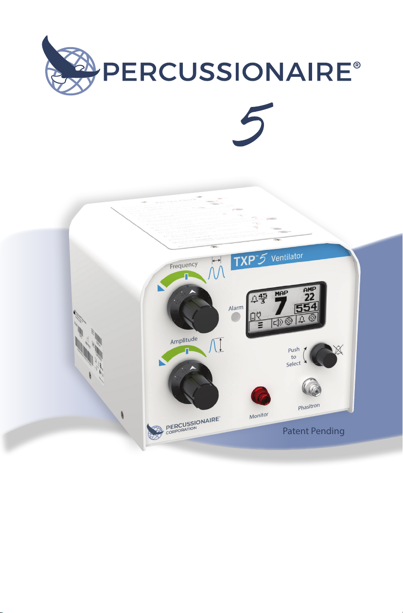
Phasitron® A50606-TXP Assembly .................................................................18
Connect Tubing Harness ...................................................................................18
Congurations ......................................................................................................19
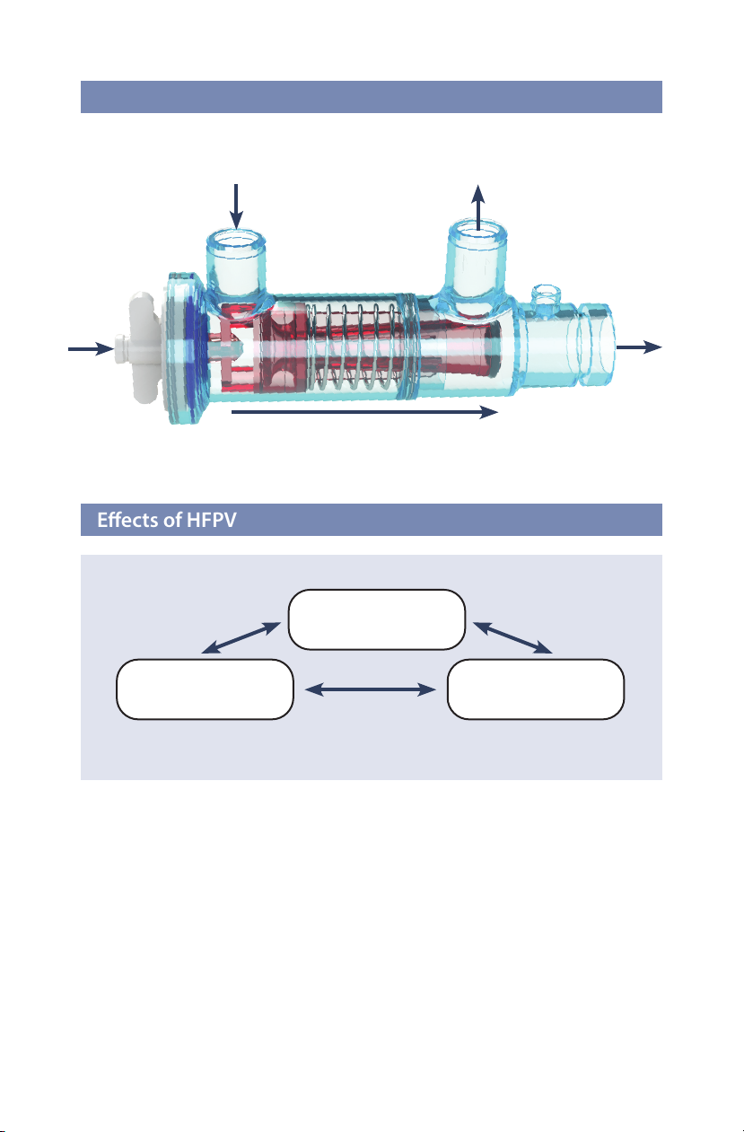
Intubated Patient with Phasitron® ........................................................19
Standard Circuit ...........................................................................................19
Optional PEEP Valve ...................................................................................19
Optional Secondary Filters ......................................................................19
Chapter 6: Pre-Use Check.................................................................................................20
Chapter 7: Ventilation Settings..................................................................................... 21
Standard Circuit Initial Settings ..................................................................... 21
Adjustment Options: Standard Circuit........................................................ 21
Increase pO2if CO2is OK ......................................................................... 21
Increase O2if CO2is OK ........................................................................... 21
Decrease CO2if O2is OK ........................................................................... 21
Adjustment Options: Standard Circuit with
Optional PEEP Valve and Inspiratory Valve ............................................... 22
Increase pO2and Decrease CO2............................................................ 22
Increase O2if CO2is OK ............................................................................ 22
Decrease Patient’s CO2if O2is OK ........................................................ 22
Increase CO2if O2is OK ............................................................................ 22
Patient Monitoring ............................................................................................. 23
Assessment................................................................................................... 23
Ventilation..................................................................................................... 23
Increase Ventilation................................................................................... 23
Oxygenation ................................................................................................ 24
Increase Oxygenation............................................................................... 24
Decrease Ventilation Increase pCO2.......................................................24
Chapter 8: Cleaning and Maintenance ...................................................................... 25
Cleaning ................................................................................................................. 25
TXP™5 Controller ................................................................................................ 25
Digital Multimeter (DMA) Screen ................................................................. 25
Phasitron® A50606-TXP Breathing Circuit Kit .......................................... 26
Cleaning and Disinfecting Solutions ........................................................... 2
Maintenance ........................................................................................................ 26
TXP™5 Controller ................................................................................................. 26
Lithium-ion Battery Care ................................................................................. 26
Battery Replacement ......................................................................................... 27
Chapter 9: Troubleshooting ........................................................................................... 28
Chapter 10: Technical Specications ......................................................................... 30
TXP™5 Ventilator .................................................................................................. 30
Measured Performance............................................................................ 30
FiO2Measurements .................................................................................. 31
Digital Multimeter (DMA) Specications ................................................... 32
Phasitron® A50606-TXP..................................................................................... 32
Battery: Lithium-ion 18650 3.7V.................................................................... 33
Chapter 11: Service and Repair .................................................................................... 34
Disposal of Equipment...................................................................................... 34
Battery Disposal................................................................................................... 34
Chapter 12: Limited Warranty ....................................................................................... 34

1
Chapter 1: Introduction
This chapter provides an overview of the TXP™5 emergency high-frequency ventilator.
High-Frequency Percussive Ventilation (HFPV) can be lifesaving for patients with
fragile, congested, or sti lungs weakened by barotrauma or infection. HFPV is a
solution that requires neither the pressure of mechanical ventilation nor the breathing
action of the patient.
HFPV provides respiratory assistance as the patient breathes through the Phasitron®.
The patented Phasitron® uses a unique venturi as a“clutch”mechanism to protect the lung
from over-pressure. By automatically adjusting to the resistance of the lung, the Phasitron®
precisely, and safely delivers the optimal amount and pressure of air required by the
alveolar space. When lung resistance is low, as in a compliant lung, all the pulsed air from
the TXP™5 enters the mouth of the venturi. Each air pulse draws up to four times as much
additional air into the venturi tube. This low-pressure entrained air automatically lls the
available space in the lung. The Phasitron® continuously and instantaneously adjusts to
keep a gentle and safe air pressure even in a compromised lung.
High-Frequency Percussive Ventilation
Phasitron® Breathing Circuit A50606-TXP
Numbers for
reference only

2
The eects of HFPV occur with or without the cooperation of the patient. HFPV provides
a sub-tidal gas exchange within the respiratory bronchioles with associated alveolar
recruitment maintaining a minimal mean intrathoracic expiratory pressure increase
for peripheral lung stabilization. This allows for mechanical ventilation to provide for
peripheral lung recruitment while minimizing the potential for induced barotrauma.
Ventilation &
Oxygenation
Mobilization of
Airway Secretions
Lung
Recruitment
Eects of HFPV
Phasitron® Breathing Circuit A50606-TXP
Exhalation port
Patient
Inhalation port
4 x amplication if needed
Air/Oxygen
inlet
Venturi as “clutch” mechanism

3
Document Symbols
NON
STERILE
LATEX
PHT DEHP
DIBP
DBP
BBP
i
C
M
N
D
h
g
y
WARNING
CAUTION
Read the manual
before use
CE marking
Manufacturer
Manufacture Date
Non-Sterile
Does Not Contain
the Phthalate
Plasticizers DEHP,
DIBP, DBP, or BBP
Type BF Applied Part
Single Patient Use
Prescription Only
Catalog Number
Lot Number
European
Representative
Not Made with
Natural Rubber Latex
Disposal

4
Warnings and Cautions
Warnings
A WARNING icon indicates a risk of injury to a patient or operator.
A CAUTION icon indicates a risk of equipment damage.
Articial Airway If the HFPV device is used on a patient with an indwelling
airway (i.e., endotracheal or tracheostomy tube), a clinician
must be present so that a one-to-one relationship exists.
These devices enhance secretion clearance. Patients must
be assessed for a reduced functional residual capacity (FRC).
Patient Monitoring Complete a clinical assessment before placing a patient on
the TXP™5 ventilator.
Personnel The operator of the TXP™5 is responsible for reading
Qualications and understanding the manual before use.
TXP™5 is a medical device designed for hospital use
by trained clinicians under the supervision of a
physician. Only change the prescription and device
settings on the order of the supervising physician.
Pre-Use Check Always conduct a pre-use check before starting HFPV
with the TXP™5.
Suctioning Perform suctioning as necessary; pulmonary alveoli cannot
be ventilated when their transmitting airways are obstructed.
Cleaning Do not use any steam cleaning methods to clean the device
or Phasitron® A50606-TXP breathing circuit.
Always follow hospital/institutional protocols for
cleaning and disinfection.
Maintenance The TXP™5 must not be opened by anyone other than
Percussionaire®-authorized service personnel.
Maintain and service the TXP™5 device according to
the recommendations provided in this manual.
Only use Percussionaire® accessories explicitly designed
for use with the TXP™5 device.
Malfunctions If the TXP™5 malfunctions, it should not be utilized
any further. Report any malfunctions immediately.
Read and All persons providing HFPV therapy must be trained
Understand Manual in the use of the TXP™5.
Safety Do not place objects on top of the TXP™5. Do not cover the
device during use. Do not lean on device.
Cautions

5
Chapter 2: Intended Use
The TXP™5 is designed for emergency ventilation of adult, pediatric, or neonatal patients.
The device is intended for hospital or pre-hospital use, emergency care,
intra-hospital, and external hospital transport. The TXP™5 is intended for use under the
supervision of a licensed physician, by both properly trained clinicians and personnel
with limited training. The TXP™5 requires a 50 psi source capable of maintaining 15 LPM.
A medical source of compressed oxygen or air is preferred, but other emergency sources
may be used.
Patient Population
Indications for Use
Absolute Contraindications
Relative Contraindications
Possible Adverse Reactions
Physiological Benets of HFPV
TXP™5 ventilator is intended for use on neonatal, pediatric, and adult patient populations.
• Untreated tension pneumothorax • Untrained or unskilled operator
• History of pneumothorax • Lack of patient cooperation
• Recent pneumonectomy • Vomiting
• Pulmonary hemorrhage • Pulmonary air leak
• Myocardial infarction (without functioning chest tube)
• Decreased cardiac output • Increased intracranial pressure
• Pneumothorax • Increased air trapping
• Hyper-oxygenation • Pulmonary air leak
• Pulmonary hemorrhage • Hyperventilation
• Gastric distension
• Recruitment of atelectatic lung • Mechanical ventilation
• Improved FRC • May improve breathing pattern
• Decreased work of breathing • Increased secretion mobilization

6
Clinical Limitations/Restrictions
Use of the TXP™5 is limited to qualied individuals who have received training.
WARNING: Suctioning should be performed as necessary; pulmonary alveoli cannot
be ventilated when airways are obstructed.
WARNING: When used, a clinician must be present so that a one-to-one relationship
exists. These devices enhance secretion clearance. Patients must be assessed pre- and
post-ventilation for a reduced functional residual capacity (FRC) or the need for assistance
in clearing airway secretions.
WARNING: When using an HME (Heat-Moisture Exchanger), connect between the
Phasitron®breathing circuit and the patient. Follow all setup instructions provided by the
HME manufacturer.
NOTE: Any HME attached to the Phasitron®breathing circuit should comply with
ISO 9360-1 or ISO 9360-2.

7
Chapter 3: System Description
The TXP™5 ventilator provides high-frequency percussive ventilation (HFPV) as the
patient breathes through the Phasitron® breathing circuit.
The Frequency knob controls the frequency rate from
approximately 200-700 pulses (inations) per minute.
NOTE: The rate may dier at dierent altitudes.
The Amplitude control knob determines the amplitude
delivered to the patient during the pulse.
NOTE: Amplitude is aected by lung compliance and
resistance.
Amplitude is attenuated by resistance and compliance to
an airway pressure.
Frequency Control Knob
Amplitude Control Knob
Controls the
high-frequency rate
Determines the
pressure amplitude
Selects menu and
silences alarms
Displays the alarm
settings, MAP,
pulse frequency
rate, and pulse
amplitude

8
Control Knob
Tubing Connectors
Use the control knob to select menus and silence alarms.
Connect the Phasitron® breathing circuit easily by
inserting the tubing connectors into the bulkhead ttings.
CAUTION: Ensure the connection is straight to
prevent crimping the O-ring and causing a leak.
Digital Multimeter (DMA)
The DMA treatment screen displays Amplitude,
Mean Airway Pressure, Frequency, alarm high and
low setpoints, battery condition, charging status,
and power plug indicator.
The multimeter has three menu options:
• Main menu
• Volume settings
• Alarm Settings
NOTE: If a technical issue arises during POST, the System Failure screen will appear.
Power-On Self-Test (POST) Mode
Push the control knob for more than .5 of a second to power on the multimeter.
The screen displays the POST screen while it evaluates system processes before
proceeding to the treatment screen. The POST screen is displayed for 3 to 5 seconds.

9 9
Treatment Screen
Main Menu Options
Once POST is complete, the treatment screen is displayed.
The treatment screen displays several menu options. Turn the knob until the desired
menu option highlights. Push the knob to select.
Turn the control knob to
highlight the main menu
button. Push the control
knob to select. A popup
will appear with menu
options.
NOTE: Displayed values may read zero if the TXP™ 5 is not on or pulsing.
Mean Airway Pressure
(MAP) Range 0-99 cmH₂O
Alarm high and low
settings
Battery status,
charging, and
indicator for AC
power
Select to open
Main Menu
Main Menu Options
Select to open
volume settings
Select to open
alarm settings
Frequency
50-999
Amplitude
(peak to trough)
Range 0- 99

10
Power O
System Information
Highlight POWER OFF by turning the
control knob. Push the control knob to
select.
Turn the control knob to highlight
SYSTEM INFORMATION.
Push the control knob to select.
A popup will appear displaying system
information. Turn the control knob to
highlight EXIT to return to the treatment
screen. Push the control knob to make
selection.

11
Exit Menu
Volume
Turn the control knob to highlight
EXIT MENU. Push the control knob to
select and return to the treatment screen.
Turn the control knob to highlight the
volume icon on the treatment screen.
Push the control knob to select.
A popup will appear displaying volume
options. Turn the control knob to highlight the
desired volume. Push control knob to select:
LOW – volume set to 25% of speaker output
MEDIUM – volume set to 50% of speaker
output
HIGH – volume set to 100% of speaker output
A conrming tone will sound when the
volume selection is made.
Turn the control knob to highlight EXIT.
Push to select. This will return the user to
the treatment screen.

12
Chapter 4: Alarms
Alarm Settings
Turn the control knob to highlight the
alarm icon. Push the control knob to
select.
An alarm popup will appear.
Turn the control knob to highlight the
value to be changed. Push to select.
Turn the control knob to raise or lower
the alarm value. Push to select.

13
When satised with the new alarm
settings, turn the control knob to
highlight the CONFIRM button. Push
to select. This will return the user to the
treatment screen.
Highlight and select EXIT to return to the
treatment screen without updating or
changing alarm settings.
The alarm parameters display on
the treatment screen.
NOTE: The process is the same for setting both high and low alarms.
NOTE: The alarm setting will not change if the user presses EXIT before conrming
the change.

14
High Priority
Loss of All Power Alarm
Alarm Conditions
A high priority alarm will alert at 1 second. During a high alarm event, the LED ashes
and a high priority alarm tone will sound. Pushing the control knob acknowledges
and silences the alarm, but the visual ashing LED continues until the alarm condition
resolves. After 30 seconds of a high priority alarm condition, a maximum volume alarm
tone will sound, overriding any pre-selected alarm volume level.
A high priority alarm will sound when the TXP™5 battery is drained beyond critical, and
the device is not connected to AC power. When battery power is less than 1%,
the screen shuts o, and the unit emits a steady tone until the control knob is pressed
to silence the alarm tone. The unit will display the battery charge symbol.
High Priority Alarm Conditions

15
Medium Priority
Battery Low
Patient Pressure Below Set Limit
Alarm Silence
A low battery medium priority alarm will alert at 10% remaining battery power.
During this medium alarm event, the LED ashes and a medium priority alarm tone will
sound. The alarm can be silenced, but the visual ashing LED continues until the alarm
condition is resolved. After 30 seconds of a medium priority alarm condition, a maximum
volume alarm tone will sound, overriding any pre-selected alarm volume level.
A medium priority alarm will alert at 1 second. During a medium alarm event, the
LED ashes and a medium priority alarm tone will sound. Pushing the control knob
acknowledges and silences the alarm, but the visual ashing LED continues until the alarm
condition is resolved. After 30 seconds of a medium priority alarm condition, a maximum
volume alarm tone overrides any selected volume level.
Pushing the control knob will silence an alarm. Once the alarm is silenced, a 2-minute
countdown begins. If, after 2 minutes, the alarm condition persists, normal alarming will
resume.
When an alarm is silenced, the alarm screen will ash (on and o) until the alarm condition
is resolved.
Medium Priority Alarm
Push button to
silence the alarm.
Alarm
silenced

16
Chapter 5: Setup
Controller and Stand
DISS Gas Connection
Blended Gas/Air Connection
Connect the ventilator to hospital wall
gas/air, blended gas, oxygen cylinders,
or a mobile compressor.
Pole stand
supplied separately.
Other manuals for TXP 5
2
Table of contents
Popular Fan manuals by other brands

STIEBEL ELTRON
STIEBEL ELTRON LWZ 70 E Operation and installation

Nuaire Group
Nuaire Group MRXBOX95AB-WM2QA11179 Installation and Maintenance

Hunter
Hunter 82040 owner's manual

Holmes
Holmes BLIZZARD HAOF-90 owner's guide

Kichler Lighting
Kichler Lighting Imari 65 instruction manual

Fantech
Fantech SER Series instruction manual

Aprilaire
Aprilaire 8145NC Installation and operating instructions

Vectaire
Vectaire RA10 installation instructions

Fantech
Fantech SHR series Installation, operation and maintenance manual

Be Cool
Be Cool BC78TU2002F manual

Clatronic
Clatronic VL 3602 instruction manual

Merox
Merox L 100 U installation instructions