Pichler LG 100 UP Specification sheet

Systematic ventilation.
COMFORT
VENTILATION
OPERATING AND
INSTALLATION MANUAL
FLUSH-MOUNTED UNIT
LG 100 UP

OPERATING AND INSTALLATION MANUAL FLUSH-MOUNTED UNIT LG 100 UP PAGE 2
Changes reserved
Contents
G
1. Introduction Page 4
2. General Page 4
U
2.1. VERSION PAGE 5
2.1.1. SINGLE-ROOM APPLICATION PAGE 5
2.1.2. MULTI-ROOM APPLICATION PAGE 6
2.2. INSTALLATION VARIANT WITH CONNECTION TO THE REVEAL PAGE 7
2.2.1. SINGLE-ROOM APPLICATION PAGE 7
2.2.2. MULTI-ROOM APPLICATION PAGE 8
2.3. OVERVIEW OF COMPONENTS PAGE 9
3. Functionality of the ventilation system Page 9
4. Designated use Page 9
4.1. INTENDED USE PAGE 9
4.1.1. STIPULATIONS FOR OPERATION WITH FIREPLACES PAGE 10
4.1.2. STIPULATIONS FOR OPERATION WITH EXTRACTOR HOODS PAGE 10
4.1.3. LIABILITY PAGE 10
4.1.4. WARRANTY PAGE 11
5. Safety Page 11
5.1. SYMBOLS USED IN THIS DOCUMENT PAGE 11
5.2. SAFETY REGULATIONS PAGE 12
5.3. SETTING UP THE UNIT PAGE 12
5.4. ELECTRICAL CONNECTION WORK PAGE 12
5.5. PLANT OPERATION PAGE 13
6. Customer service Page 14
7. Design of the ventilation unit Page 14
8. How to operate the unit Page 15
9. MINI control unit Page 16
9.1. FUNCTIONS PAGE 16
9.2. BUTTONS AND LEDS PAGE 16
10. Operation via PICHLER APP and PICHLER Connect Page 17
10.1. EASY OPERATION WITH THE PICHLER APP PAGE 17
10.2. REMOTE ACCESS WITH PICHLER CONNECT PAGE 17
10.3. DATA PROTECTION PAGE 17
10.4. CREATE AN ACCOUNT PAGE 18
11. Error & warning messages Page 20
11.1. LED ON THE VENTILATION UNIT PAGE 20
11.2. MINI CONTROL UNIT PAGE 20
11.3. PICHLER APP PAGE 20
12. Filter service Page 21
12.1. MINI CONTROL UNIT FILTER MESSAGE PAGE 21
12.1.1. CLEARING THE MINI CONTROL UNIT FILTER MESSAGE PAGE 21
12.2. FILTER MESSAGE ON THE UNIT PAGE 21
12.3. FILTER MESSAGE VIA PICHLER APP PAGE 21
12.4. FILTER CHANGE PAGE 22
12.5. PROCEDURE FOR THE FILTER CHANGE PAGE 22
GENERAL
USERS
SPECIALIST PERSONNEL

OPERATING AND INSTALLATION MANUAL FLUSH-MOUNTED UNIT LG 100 UP PAGE 3
Changes reserved
S - /
13. Transport, storage and disposal Page 24
13.1. TRANSPORT, STORAGE AND PACKAGING PAGE 24
13.2. DISPOSAL PAGE 24
14. Technical specifications Page 25
14.1. UNIT SET-UP AND DIMENSIONS PAGE 25
14.2. SYSTEM DIAGRAM PAGE 26
14.3. SAFETY DEVICES PAGE 27
14.4. DEVICE DATA PAGE 27
14.5. SOUND DATA PAGE 28
15. Control Page 29
15.1. FROST PROTECTION WITH PREHEATING BATTERY PAGE 29
15.2. MOISTURE PROTECTION PAGE 29
15.3. FROST PROTECTION WITHOUT A PREHEATING BATTERY PAGE 29
15.4. VOC/ECO2 CONTROL PAGE 30
15.5. OUTDOOR AIR QUALITY CONTROL PAGE 30
15.6. SERVICE LEVEL OPERATION VIA APP PAGE 30
16. Mounting Page 31
16.1. INSTALLATION OF THE SLIDE-IN MODULE IN THE FLUSH-MOUNTED HOUSING PAGE 31
16.2. ELECTRICAL CONNECTION PAGE 35
16.3. ADJUSTING THE AIR REGULATION SHEETS PAGE 37
16.3.1. SINGLE-ROOM APPLICATION PAGE 37
16.3.2. MULTI-ROOM APPLICATION PAGE 38
16.4. INSTALLATION OF THE DESIGN FRONT PAGE 39
S -
17. Maintenance and cleaning Page 40
17.1. SAFETY INSTRUCTIONS PAGE 40
17.2. MAINTENANCE INSTRUCTIONS PAGE 40
17.3. ENTHALPY EXCHANGER PAGE 40
17.4. CLEANING THE EQUIPMENT HOUSING INSIDE PAGE 41
17.5. SERVICE TABLE PAGE 42
18. Commissioning Page 44
18.1. BASIC QUESTIONS FOR COMMISSIONING PAGE 44
18.2. SETTING SYSTEM PARAMETERS PAGE 44
19. Error description Page 45
19.1. DESCRIPTION OF ERRORS INDICATED BY THE MINI CONTROL UNIT PAGE 45
19.2. DESCRIPTION OF ERRORS INDICATED BY THE VENTILATION UNIT PAGE 46
20. Installation/operation of service software and firmware
updates Page 46
21. Spare parts and accessories Page 47
21.1. CONTROL ELEMENTS PAGE 47
21.2. AIR FILTERS PAGE 47
22. Changes reserved Page 47
GENERAL
USERS
SPECIALIST PERSONNEL

OPERATING AND INSTALLATION MANUAL FLUSH-MOUNTED UNIT LG 100 UP PAGE 4
Changes reserved
J. Pichler
Gesellschaft m.b.H.
AUSTRIA 9021
KLAGENFURT
Karlweg 5
T +43 (0) 463 32769
www.pichlerluft.at
Equipment type:
08LG100DEFV
Year of manufacture:
Volume flow:
max. 80 m3/h
Weight: approx. 35 kg
Dimensions WxHxD:
599x945x203 mm
Voltage/frequency:
230 V / 50 Hz
Power consumption:
max. 320 W
Order number:
Serial number:
This manual contains notes and information on safe operation and proper installation of the decentralised compact ventilation unit
LG100 and on its use and servicing. Furthermore, reference this manual during servicing to ensure proper execution of the tasks.
Troubleshooting and procedures may be performed by an installation company (specialist company) only.
Changes reserved: This manual has been compiled with the utmost care. This does not, however, imply any rights. Your unit may
therefore vary slightly from the description in this manual.
Our "General terms and conditions" in their latest version apply.
2. General
Dear customer,
Thank you for choosing the decentralised compact ventilation unit LG100 from PICHLER.
To operate your compact ventilation unit safely, properly and economically, please read this manual carefully and follow the in-
structions provided. Keep this operating manual in a safe place and readily available at all times. These units are subject to ongoing
improvement and further development. Your unit may therefore vary slightly from the description in this manual.
Use the ventilation unit only when in perfect condition and for its designated use, be aware of safety and any hazards and cognisant
of all the notes and information contained in this manual.
1. Introduction
J. Pichler
Gesellschaft m.b.H
AUSTRIA 9021
KLAGENFURT
Karlweg 5
T +43 (0) 463 32769
www.pichlerluft.at
Equipment type:
08LG100UPFV
Year of manufacture:
Volume flow:
max. 80 m3/h
Weight: approx. 15 kg
Dimensions WxHxD:
504x882x192 mm
Voltage/frequency:
230 V / 50 Hz
Power consumption:
max. 320 W
Order number:
Serial number:
J. Pichler
Gesellschaft m.b.H. AUSTRIA 9021
KLAGENFURT
Karlweg 5
T +43 (0) 463 32769
www.pichlerluft.at
Equipment type:
08LG100APFV
Year of manufacture:
Volume flow:
max. 60 m3/h
Weight: approx. 25 kg
Dimensions WxHxD:
525x910x203 mm
Voltage/frequency:
230 V / 50 Hz
Power consumption:
max. 320 W
Order number:
Serial number:
Compact ventilation unit LG100 ceiling variant with
preheating battery
Compact ventilation unit LG100 flush-mounted variant
with preheating battery
Compact ventilation unit LG100 surface-mounted variant with
preheating battery
Please always keep the model and serial number (see name-
plate on unit) at hand in the case of queries or when ordering
spare parts.
Please contact us if you have any further questions or if you lose
this documentation.
Your PICHLER team
J. Pichler Gesellschaft m.b.H.
9021 KLAGENFURT
Karlweg 5, Postfach 32
T+43 (0)463 32769
USERS GENERALSPECIALIST PERSONNEL

OPERATING AND INSTALLATION MANUAL FLUSH-MOUNTED UNIT LG 100 UP PAGE 5
Changes reserved
2.1. Version
2.1.1. SINGLE-ROOM APPLICATION
The compact ventilation unit LG100 in flush-mounted design consists of a flush-mounted housing (3) and a ventilation unit as slide-in
module (2).
The ventilation unit is closed with a design front (1) at its front side. The outdoor air and exhaust air connections are led outside
through a wall duct (5). On the rear side of the housing the compensation plate (4) still has to be mounted. The outdoor air and
exhaust air connections are sealed by means of weather protection grilles (6a or 6b).
Single-room application
GENERAL
USERS
SPECIALIST PERSONNEL
In the shell construction phase, the flush-mounted housing(3) including the compensation plate (4) and wall duct (5) is mounted. In
the course of the installation work, the slide-in module (2) is inserted into the flush-mounted housing (3) and is electrically connected.
3, 4, 5, 6a and 6b are not dealt with in this installation manual.

OPERATING AND INSTALLATION MANUAL FLUSH-MOUNTED UNIT LG 100 UP PAGE 6
Changes reserved
3, 4, 5, 6a and 6b are not dealt with in this installation manual.
2.1.2. MULTI-ROOM APPLICATION
The compact ventilation unit LG100 in flush-mounted design consists of a flush-mounted housing (3) with pre-assembled connectors
and a ventilation unit as slide-in module (2).
The ventilation unit is closed with a design front (1) at its front side. The outdoor air and exhaust air connections are led outside
through a wall duct (5). On the rear side of the housing the compensation plate (4) has to be mounted. The outdoor air and exhaust air
connections are sealed by means of weather protection grilles (6a or 6b).
In the shell construction phase, the flush-mounted housing (3) including the compensation plate (4) and wall duct(5) is mounted.
For multi-room applications, the piping leading upwards for the supply and extract air is provided in addition. In the course of the
installation work, the slide-in module (2) is inserted into the flush-mounted housing (3) and is electrically connected.
Multi-room application
USERS GENERALSPECIALIST PERSONNEL

OPERATING AND INSTALLATION MANUAL FLUSH-MOUNTED UNIT LG 100 UP PAGE 7
Changes reserved
2.2. Installation variant with connection to the reveal
2.2.1. SINGLE-ROOM APPLICATION
The compact ventilation unit LG100 in flush-mounted design for reveals consists of a flush-mounted housing(3) and a ventilation unit
as slide-in module (2).
The ventilation unit is closed with a design front(1) at its front side. The outdoor air and exhaust air connections are led outside
through a wall duct (4) and must be flush with the masonry. The wall duct is connected to the connection set(6) and led towards the
reveal. The outdoor and exhaust air connections are sealed by means of a weather protection grille (7).
In the shell construction phase, the flush-mounted housing (3) including the wall duct (4) is mounted.
The connection set (6) is mounted in the process of insulating the exterior walls and integrated into the insulation. In the course of the
installation work, the slide-in module (2) is inserted into the flush-mounted housing (3) and is electrically connected.
3, 4, 5, 6 and 7 are not dealt with in this installation manual.
Single-room application
GENERAL
USERS
SPECIALIST PERSONNEL

OPERATING AND INSTALLATION MANUAL FLUSH-MOUNTED UNIT LG 100 UP PAGE 8
Changes reserved
In the shell construction phase, the flush-mounted housing(3) including the wall duct(4) is mounted.
For multi-room applications, the piping leading upwards for the supply and extract air is provided in addition. The connection set (6)
is mounted in the process of insulating the exterior walls and integrated into the insulation. In the course of the installation work, the
slide-in module (2) is inserted into the flush-mounted housing(3) and is electrically connected.
2.2.2. MULTI-ROOM APPLICATION
Multi-room application
The compact ventilation unit LG100 in flush-mounted design for reveals consists of a flush-mounted housing(3) with pre-assembled
connectors and a ventilation unit as slide-in module (2).
The ventilation unit is closed with a design front(1) at its front side. The outdoor air and exhaust air connections are led outside
through a wall duct (4) and must be flush with the masonry. The wall duct is connected to the connection set(6) and led towards the
reveal. The outdoor and exhaust air connections are sealed by means of a weather protection grille (7).
3, 4, 5, 6 and 7 are not dealt with in this installation manual.
USERS GENERALSPECIALIST PERSONNEL

OPERATING AND INSTALLATION MANUAL FLUSH-MOUNTED UNIT LG 100 UP PAGE 9
Changes reserved
Komponentenübersicht
Bezeichnung Artikelnummer Skizze
Scope of supply
Slide-in module and design front
Slide-in module with preheating battery
08LG100UPF
Slide-in module without preheating battery
08LG100UPFV
Standard design front
08LG100UPAPDF1A
Further design fronts
available on request!
2.3. Overview of components
With the ventilation unit LG100 you can provide a maximum degree of flexibility to your ventilation concept. Depending on the design
variants of the flush-mounted housing, further rooms can be integrated via the KOMFLEX air duct system. The used air is extracted
from the living areas, and fresh, filtered outdoor air is supplied. In this process, the high-quality enthalpy exchanger allows for
ecient heat and moisture recovery and ensures a well-balanced room humidity and a pleasant room climate.
Highly ecient and low noise EC radial fans allow for extremely energy-saving and low-noise operation. In the switched o state,
the outdoor and exhaust air openings are automatically closed mechanically. The integrated sensors record the VOC and eCO2
concentration of the extract air and, in automatic mode, allow for an operation depending on the room air quality.
The decentralised compact ventilation unit LG100 is controlled easily and intuitively via a pushbutton that is positioned directly on the
unit, or via the PICHLER APP. Therefore the unit comes with a WLAN connection as a standard feature. Optionally you can additionally
connect an external control unit via cable connection.
3. Functionality of the ventilation system
4. Designated use
4.1. Intended use
The compact ventilation unit LG 100 is intended for the installation into ventilation and air conditioning systems for controlled
domestic ventilation in small and medium-sized residential units (approx. 80 m²). The purpose of controlled mechanical ventilation
and deaeration of domestic areas is to improve air quality and reduce the heating energy demand through the use of a highly ecient
heat recovery system, and to influence indoor air humidity. The scope and intended use of the unit is limited to the application in
residential and recreational spaces for the suction of used air and the supply of fresh, tempered outdoor air at maximum air flow
temperatures of -15°C to +35°C. Furthermore the airflow must be free from aggressive vapours and substances causing increased
wear. Any other use shall be deemed contrary to designated use. The manufacturer shall accept no responsibility for damages
or consequential damages arising from improper use. Designated use also includes adherence to our prescribed operating and
installation manual. This unit is available to the general public and is intended for installation in residential or industrial buildings. The
unit is used for mechanical aeration and ventilation of indoor air and, when combined with a heater battery, is also used to preheat
air. The compact ventilation unit LG100 is not suitable for outdoor installation and may be installed in suitable and frost-free interior
areas only. The ventilation unit is not suitable for drying new buildings.
This unit can be used by children from an age of 8 years and furthermore by persons with reduced physical, sensory or mental
capabilities or a lack of experience or knowledge, if they are supervised or if they have been instructed on how to use the unit safely
and if they understand the hazards resulting therefrom. Children must not play with the unit. Cleaning and user maintenance must
not be carried out by children without supervision.
GENERAL
USERS
SPECIALIST PERSONNEL

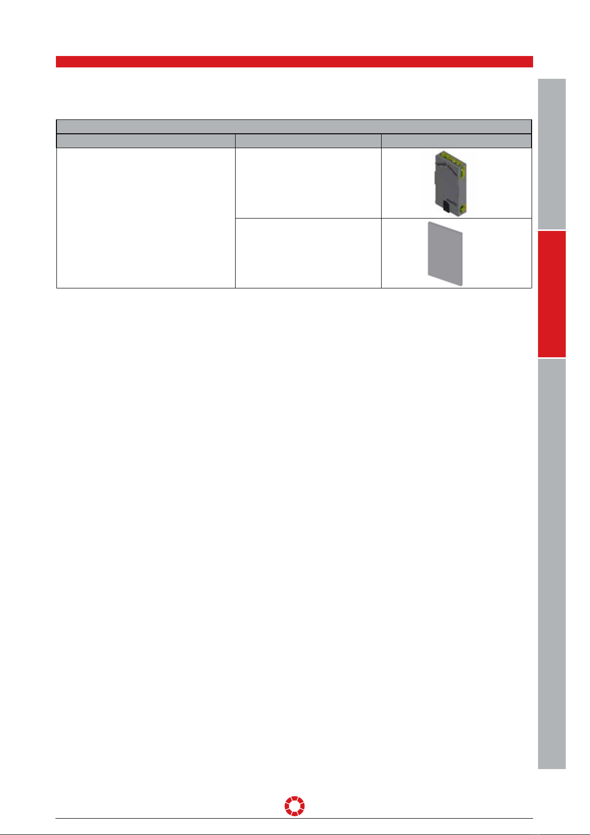
OPERATING AND INSTALLATION MANUAL FLUSH-MOUNTED UNIT LG 100 UP PAGE 10
Changes reserved
The compact ventilation unit is not a ready-to-use product. It must not be put into operation until it has been properly installed and
connected. Only qualified and instructed personnel may carry out connection and service work on the unit.
B
In order to prevent uncontrolled condensate formation in the unit, continuous operation at outdoor temperatures
below 0°C with an extract humidity of more than 60% must be avoided (e.g. private spa area).
B
Persons transporting, installing or working on the unit must have read and understood the operating instructions, in
particular Section5 "Safety". The end user must also be instructed on potential hazards.
4.1.1. STIPULATIONS FOR OPERATION WITH FIREPLACES
4.1.2. STIPULATIONS FOR OPERATION WITH EXTRACTOR HOODS
4.1.3. LIABILITY
Local requirements must be taken into consideration by compliance with corresponding standards, laws and directives.
The decentralised compact ventilation unit LG100 may only be installed in rooms, flats or utilisation units of a comparable size in
which fireplaces dependent on room air are installed, if:
• simultaneous operation of room air-dependent fireplaces and the air extraction unit is prevented by safety devices, or
• the flue gas evacuation of the room air-dependent fireplace is monitored by special safety devices. In the case of room-air
dependent fireplaces for liquid or gaseous fuels, activation of the safety device must lead to the switch-o of the fireplace or
ventilation unit. In the case of room-air dependent fireplaces for solid fuels, activation of the safety device must lead to the switch-o
of the ventilation unit.
The ventilation units for the controlled aeration and ventilation of a flat or a comparable living unit must not be installed if room
air-dependent fireplaces in the living unit are connected to exhaust gas systems, which themselves have multiple connections.
Normal operation of the ventilation systems requires the possibility of shutting potentially available combustion air ducts as well as
exhaust gas systems o from room air-dependent fireplaces. In the case of exhaust gas systems of fireplaces for solid fuels, it must
be ensured that the shut-o device can only be operated manually. The position of the shut-o device must be identifiable by the
setting of the operating handle. This specification is considered as complied with if a shut-o device against soot is used.
Fire protection requirement: With regard to the fire protection installation regulations for the set-up of the ventilation unit, the
provisions of national law, in particular the building regulation concerning the fire protection requirements with regard to ventilation
systems in the relevant latest version must be observed.
Due to the heavy load as well as the irregular operation, the extract air of an existing kitchen extractor hood must not be integrated
into the dwelling's ventilation system. Extract air from such extractor hoods must be conducted separately by means of an exhaust
air pipe via the roof. The supply air must be provided for separately (e.g. by window ventilation).
If an extractor hood without the separate provision of supply air is operated, the balance of the air volume in the dwelling is no longer
provided for and the proper function of the dwelling's ventilation system is no longer ensured (odour diversion, etc.). Another option is
to operate the extractor hood in recirculation mode.
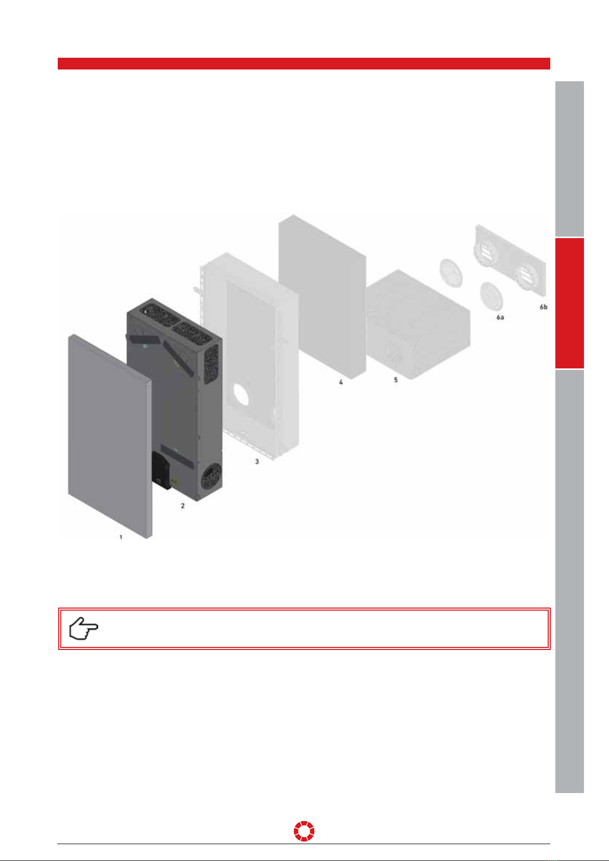
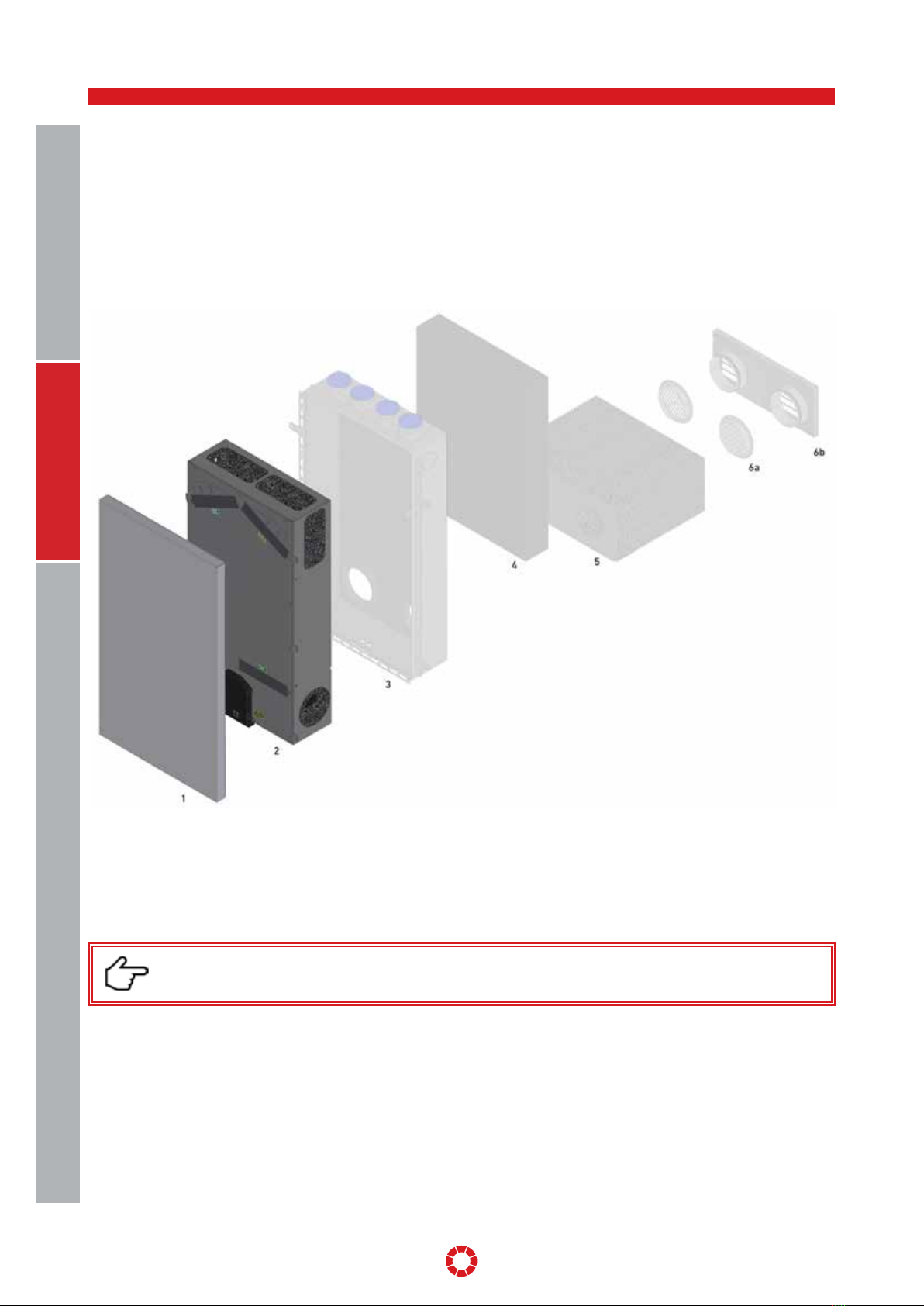
The compact ventilation unit LG 100 has been developed and manufactured for controlled mechanical ventilation and deaeration of
spaces with purposes similar, for example, to seminar rooms and small oces. Proper use of the ventilation systems have the facility
to be shut o from fireplaces dependent on ambient air.
Any other use than the one described in Section4 shall be deemed improper and may cause personal injury or damage to the
compact ventilation unit, for which the manufacturer shall accept no liability.
USERS GENERALSPECIALIST PERSONNEL

OPERATING AND INSTALLATION MANUAL FLUSH-MOUNTED UNIT LG 100 UP PAGE 11
Changes reserved
B
Attention/Note!
4.1.4. WARRANTY
5. Safety
The warranty period shall commence after the unit is put into operation, but no later than one month after delivery. Warranty
details can be found in our “General terms and conditions” in their latest version as well as the merchant conditions of your
respective country. The warranty shall be subject to proof of services performed as per our instructions and executed by a licensed
installer/specialised company. Warranty claims shall be limited to material and/or constructional defects occurring during the
warranty period. In the event of a warranty claim, the compact ventilation unit LG100 must not be dismantled without prior written
authorisation from the manufacturer. The manufacturer's liability shall be limited to spare parts installed by an installation company
approved by the manufacturer. The warranty shall automatically lapse at the end of the warranty period, following improper operation
such as operation without filters, if parts other than original manufacturer-supplied parts are installed, or if unauthorised changes
are made to the unit. Furthermore, the warranty is automatically rendered void by failure to comply with the information in this
operating and installation manual.
Read this operating and installation manual carefully and observe the safety instructions while you carry out installation,
commissioning, servicing or general work on the ventilation unit. Keep the operating and installation manual near the unit for its
entire service life.
Always observe the safety regulations, warnings, notes and instructions given in this operating manual. The specifications given
in this document must not be altered. Non-observance of these safety regulations, warnings, notes and instructions may lead to
physical injury or damage to the compact ventilation unit.
The conclusion of a service contract is recommended to ensure that the unit will be checked at regular intervals. Ask your supplier
about approved specialised companies/installers in your area.
The following Safety symbols highlight text containing warnings in respect of danger and potential hazards. Please familiarise
yourself with these symbols.
5.1. Symbols used in this document
B
Attention – High voltage! Ignoring this warning may lead to injury or threat to life and limb.
B
Attention! Ignoring this warning may lead to injury or threat to life and limb and/or damage to the unit.
The manufacturer accepts no responsibility for any damage due to:
• non-compliance with the safety, operating and servicing instructions given in this operating and installation manual.
• the installation of spare parts that have not been supplied by the manufacturer, the responsibility for the use of such spare parts
being fully borne by the system builder/installer.
• normal wear and tear.
GENERAL
USERS
SPECIALIST PERSONNEL

OPERATING AND INSTALLATION MANUAL FLUSH-MOUNTED UNIT LG 100 UP PAGE 12
Changes reserved
B
Warning: hazardous electrical voltage! Ignoring the danger may result in death, injuries or material damage. Before
carrying out any work on live parts, the unit must always be disconnected completely from the power supply (all
poles) and secured against being switched back on.
5.4. ELECTRICAL CONNECTION WORK
B
Electrical connection work and work on the system's electrical components may be carried out by authorised electri-
cians only, in compliance with national and local regulations.
5.2. Safety regulations
Installation, initial start-up, maintenance and repairs must only be carried out by an authorised specialist company.
Over and above this operating and installation manual, local and national regulations and standards shall also apply to the operation
of this unit without limitation.
Take instruction from your installer on the unit and on its control unit following installation. The ventilation unit must only be used in
accordance with the information provided in Section4 "Designated use".
All safety and danger notices attached to the unit and specified in this description must be observed.
In the event of malfunctioning, switch o the unit immediately and disconnect the power plug. The unit must be appropriately secured
against restart. Faults must be remedied immediately.
After repairs and maintenance work, qualified personnel must verify that the unit is safe to operate.
Attachment or installation of additional parts and components is not permitted. Any modification of the compact ventilation unit is
prohibited. Only original spare parts may be used.
Modifications and alterations to the ventilation unit are prohibited and absolve the manufacturer from all warranties and liability.
Ensure that children do not play with the unit.
Installation shall be carried out in accordance with the general local building, safety and installation regulations of the relevant
community or the water and electricity department and other bodies. The unit may only be installed in frost-free and dry rooms.
The room temperature at the place of installation must be consistently between +5°C min. and +35°C max. The unit is designed for
upright installation or wall installation and may only be set up on a suitable, load-bearing construction. The unit must not be exposed
to vibration of any kind.
Suitable drainage of condensate arising during operation of the unit will be required, including an eective odour blocking trap (si-
phon). Installations for water, heating and condensate connections may be performed by a specialist only. The unit must be installed
and executed appropriately so as to ensure seal-tightness and eective condensate drainage in order to exclude the possibility of
building damage. Eective condensate drainage must be verified on-site prior to initial start-up and after servicing the unit. The maxi-
mum permissible load must be observed when transporting the unit.
Components of the ventilation unit, e.g. air ducts which may need to be installed in unheated areas, must be suitably insulated to
prevent heat loss or condensate formation (for temperatures below dew point). Observe all locally-applicable construction and fire
protection guidelines, regulations and standards. If necessary, appropriate suitable measures should be taken when installing the
unit, e.g. installation of fire dampers in air ducts, etc.
5.3. Setting up the unit
B
The national and local regulations must be heeded when installing and setting up the unit. The unit may only be
installed in compliance with national installation regulations.
USERS GENERALSPECIALIST PERSONNEL

OPERATING AND INSTALLATION MANUAL FLUSH-MOUNTED UNIT LG 100 UP PAGE 13
Changes reserved
B
Any work practices that could potentially impair the safety of the unit are prohibited! To ensure safe operation, safety
devices must not be removed or bypassed.
Electrical equipment and the unit's warning and protective devices must be inspected regularly to ensure that they are in perfect
working order. In the event of faults in the electrical power supply or identification of defects e.g. loose connections or burnt cables,
the unit must be put out of operation immediately. Damaged or faulty power supply cables to the unit must be repaired immediately
to avoid hazards. The unit may not be operated until safe operational conditions are restored.
Fault finding and immediate remediation of electrical defects and malfunctions shall be carried out by authorised electricians only.
All protective measures must be inspected (e.g. earth resistance etc.) after completion of electrical work on the unit.
For details, see Section16.2. “Electrical connection”
B
Before opening the unit and when carrying out work on the unit, e.g. maintenance work and repairs, the unit must be
isolated from the mains (all poles disconnected) and secured against being switched back on for the duration of the
work. The compact ventilation unit must be connected to a 230V / 50Hz voltage supply and with the correct phases.
The mains supply cable must be provided with a strain relief.
To the external interfaces exclusively fittings may be connected for which it is proven that there is an electrically
protective separation between the interface and those active parts of the fitting, which are not operated with safety
extra-low voltage (SELV/PELV), in compliance with DIN EN 1140, e.g. by double or reinforced insulation complying
with DIN EN 60335-1 or DIN EN 60730-1.
GENERAL
USERS
SPECIALIST PERSONNEL
5.5. Plant operation
B
Operation of the ventilation unit is permitted only if all built-in parts provided, e.g. silencers etc., have been properly
connected.
B
In the event of any errors or defects that can cause harm to persons or property, the system must be put out of
operation immediately. Further use must be actively prevented until the unit is fully repaired.
B
Operation of the unit is exclusively permissible with a connected air duct or mounted system components such as
silencers, in order to ensure that, for example, fans or electrical installation parts cannot be touched with the hand.
If error messages are output or in the case of damage, the ventilation unit must be switched o and disconnected from the mains
immediately. When opening the unit or when removing cover fronts, keep safety and potential hazards in mind. Any work practices
that could potentially impair the safety of the unit are prohibited.
The compact ventilation unit may be operated only in accordance with the project documentation, which shall comply with the
Equipment and Product Safety Act and the pertinent provisions of the EC Directives and Standards. Consider environmental impacts
and refrain from installing the ventilation unit in the vicinity of flammable liquids or gases, in swimming pools or in areas exposed to
chemicals or hazardous substances. Never operate the ventilation unit without air filters. The air filters must be checked regularly
for dirt and damage and replaced, if necessary. The air filters must be changed at least every six months or when the “Change Filter”
message appears on the control unit. Use original replacement filters only. If the plant is not used in summer, the air filters must, for
hygienic reasons, be replaced prior to restarting.
Comply with safety requirements and standards when operating the ventilation unit simultaneously with ambient air-dependent
fireplaces. When using fireplaces dependent on ambient air, combustion air supply must be provided separately. Due to the heavy
load as well as the irregular operation, extractor hoods must in no case be integrated into the exhaust duct of the compact ventilation
unit. Exhaust air extractor hoods must be operated via separate air pipes with suitable air replenishment, e.g. by means of window
ventilation or in air recirculation mode. For details regarding this matter, see Section4.1.1. and 4.1.2.

OPERATING AND INSTALLATION MANUAL FLUSH-MOUNTED UNIT LG 100 UP PAGE 14
Changes reserved
7. Design of the ventilation unit
The compact ventilation unit LG 100 consists of:
• a compact, thermally insulated and soundproof EPP housing
• a device enclosure made of galvanised sheet steel
• a design front that comes equipped as a standard with an exterior powder coating in RAL9003
• a highly ecient enthalpy exchanger
• energy-saving EC radial fans
• an integrated sensor system for measuring the volumetric flow, temperature, relative humidity and VOC/eCO2 concentration
• Outdoor air and extract air filters ISO Coarse 70% and supply air filter ISO ePM1 55%
• an integrated filter monitoring function – when the time interval is reached
• standard operation via pushbutton on the unit, WLAN interface for control via the PICHLERAPP and for remote access via
PICHLERConnect and optionally with the control unit “MINI” for setting the basic functions.
Zuluftfilter ePM1 55%
Enthalpietauscher
FOL-Klappe
Abluftfilter ISO Coarse 70%
AUL-Klappe
Außenluftfilter ISO Coarse 70%
Illustration showing the design of a ventilation unit
6. Customer service
J. Pichler Gesellschaft m.b.H.
9021 KLAGENFURT
Karlweg 5, Postfach 32
T+43 (0)463 32769
USERS GENERALSPECIALIST PERSONNEL
Please contact the installer of your ventilation and air conditioning system or contact us directly for any questions relating to the
compact ventilation unit LG100.
Supply air filter ePM1 55%
Enthalpy exchanger
Exhaust air flap
Extract air filter ISO Coarse 70%
Outdoor air filter ISO Coarse 70%
Outdoor air flap

OPERATING AND INSTALLATION MANUAL FLUSH-MOUNTED UNIT LG 100 UP PAGE 15
Changes reserved
The ventilation unit is switched on by pressing the operating button twice and starts running at ventilation level 1. The LED blinks
three times at frequent intervals with one green flash in each case. The outdoor air and exhaust air flap opens and the fans convey the
selected operating volume flow of ventilation level 1. With every further push of the button the ventilation unit is switched to the next
higher ventilation level. When the “Automatic” ventilation level (LED flashing green 4 x) has been reached, the ventilation unit switches
back to the “Standby” mode, and switching starts again from the first level. In the Standby mode, the fans switch o, and the outdoor
air and exhaust air flap closes. The current operating state is indicated by the flashing patterns specified in the table below.
Wake-up call:
After showing the respective flashing pattern, the LED changes to the “Sleeping mode”, the ventilation unit continuing its operation at
the ventilation level currently set.
By pressing the operating button, a “wake-up call” is carried out first and the sleeping mode of the LED is stopped. The LED indicates
the current operating status (ventilation level, error and filter messages) by the dierent flashing modes. The flashing modes are
repeated 3x, then the LED returns to the sleeping mode again.
In order to change the ventilation level, the button on the ventilation unit must be pressed after the “wake-up call” and within the flashing
pattern (3 repetitions).
The ventilation unit can be operated without a control unit via a button on the bottom side of the unit. A green LED indicates the dierent
operating states of the ventilation unit. A red LED indicates an error or a warning message of the unit. A detailed description of the error
codes can be found in Section 19.2.
8. How to operate the unit
LED and operating button on the bottom side of the unit
LED
Operating button
Detailed view
GENERAL
USERS
SPECIALIST PERSONNEL
Pattern Operation
Flashing green 1 x Ventilation level 1
Flashing green 2 x Ventilation level 2
Flashing green 3 x Ventilation level 3
Flashing green 4 x “Automatic” ventilation level
LED flashing green permanently Access point for coupling to the WLAN
Pattern Operation
Flashing red 1-5 x Switch the unit to a deenergized state by switching it o and on. If the
error message remains active, please contact the customer service.
Flashing red 6 x Merely indicates a risk of frost or condensation, but is still in operation.
Flashing red 7 x The unit cannot establish an Internet connection.

OPERATING AND INSTALLATION MANUAL FLUSH-MOUNTED UNIT LG 100 UP PAGE 16
Changes reserved
The following compact ventilation unit functions
can be indicated and configured with the MINI control unit:
• Ventilation level of the compact ventilation unit
• Display of the filter change message
• Display of the fault messages via LED
• Boost ventilation mode for a defined time
• WIFI-modes
9. MINI control unit
9.1. Functions
9.2. Buttons and LEDs
1. Plus button
Increasing the ventilation level
2. Minus button
Reducing the ventilation level
3. Error LED
Indicates errors with dierent flashing patterns that light up
4. Filter LED
After the filter time has elapsed, the filter must be checked.
For acknowledging the filter message, push the reset button.
5. WiFi button
- Press 1x to activate the WiFi mode
- Press for 2 sec. to deactivate the WiFi mode
- Press for 5 sec. to call the Access Point mode
6. WiFi LED
- LED o = WiFi deactivated
- LED is lit = WiFi mode
- LED flashes = Access Point mode
7. Boost button
Activates ventilation level 3 (boost ventilation level) for a
defined period of time (standard: 60 minutes).
8. Boost LED
Is lit if activated.
The LED of the current ventilation level is lit and the LED of
ventilation level 3 flashes.
9. Ventilation level LEDs
Indicate the current ventilation level.
If all three LEDs are active, this corresponds to the automatic
mode. The ventilation unit follows a demand-responsive air
volume regulation via VOC.
Functions of the MINI control unit
USERS GENERALSPECIALIST PERSONNEL
Bedieneinheit MINI

OPERATING AND INSTALLATION MANUAL FLUSH-MOUNTED UNIT LG 100 UP PAGE 17
Changes reserved
PICHLER APP:
Error messages
via PUSH
notification
When the defined time (configurable) has elapsed in the highest ventilation level, ventilation operation switches back automatically to
the ventilation level set last. Alternatively, you can end the boost ventilation mode manually before the time has passed. Simply press
the [-]-button on your control unit.
Ventilation level 1
Boost ventilation mode for a defined time
Ventilation level 2
Boost ventilation mode for a defined time
Ventilation level 3
Boost ventilation mode for a defined time
Pattern Operation
Green LED level 1 is lit
Ventilation level 1
Green LED level 2 is lit
Ventilation level 2
Green LED level 3 is lit
Ventilation level 3
Green LED levels 1 to 3 are lit
“Automatic” ventilation level
10. Operation via PICHLER APP and PICHLER Connect
User-friendly: the compact ventilation unit can be operated
easily with our free smartphone app for Android and iOS,
whether you are at home or on the move.
Load and install the PICHLER APP from the App Store or
from the Google Play Store. The PICHLER APP can control the
ventilation unit directly or via the Internet.
By pressing the WiFi button (see red marking in the illustration
on the left) for 5seconds, the Access Point mode of the
ventilation unit is activated, which is indicated when the WiFi
LED flashes green.
10.1. Easy operation with the PICHLER APP
Operational safety: remote access allows the PICHLER customer service to respond quickly and
easily in the event of faults.
When you have installed the PICHLER APP and establish a connection to the device, we assume that you accept our current data
privacy statement (see: www.pichlerluft.at/datenschutz.at).
10.2. Remote access with PICHLER Connect
10.3. Data protection
connect.
GENERAL
USERS
SPECIALIST PERSONNEL

OPERATING AND INSTALLATION MANUAL FLUSH-MOUNTED UNIT LG 100 UP PAGE 18
Changes reserved
Then press the “Search units...” button.
If the ventilation unit is found via the Access Point mode, a 12-digit
number is shown.
If no number is shown, the smartphone
is no longer connected to the ventilation unit.
Please start again.
When the Access Point mode is active, the ventilation unit is visible
via the WLAN settings of the smartphone. Select the network
“LG100AHU” and enter the password “Pichlerluft1234”.
When a connection with the ventilation unit has been established
successfully, open the PICHLERAPP.
The following screen is shown:
Press the “LG100 Direct” button in order to establish a direct
connection with the ventilation unit.
Press the “Login” button. The app checks the connection and
loads the data of the ventilation unit.
The following screen will open.
Go to the „Wifi settings” menu.
USERS GENERALSPECIALIST PERSONNEL
10.4. Create an account

OPERATING AND INSTALLATION MANUAL FLUSH-MOUNTED UNIT LG 100 UP PAGE 19
Changes reserved
The same 12-digit number as in the Access mode is
shown.
If no number is shown, either the ventilation
unit or your smartphone is not connected
to the Internet router.
Please start again.
Connect your smartphone with the Internet router and
select “Connect via Internet” on the screen.
In order to connect the ventilation unit with the Internet router,
you have to enter the network name (WIFI-SSID), the WiFi pass-
word and the WiFi encryption. Then press “Accept”. The direct
connection between the ventilation unit and your smartphone is
interrupted.
If you have successfully established a connection between the ventilation unit and your smartphone via the Internet, you have to
allocate an account name, e-mail address and a password. Press the “Save” button and your account is created.
Then you can control your ventilation unit globally via your smartphone.
As you are connected with the same network, press the “Search
units...” button.
GENERAL
USERS
SPECIALIST PERSONNEL

OPERATING AND INSTALLATION MANUAL FLUSH-MOUNTED UNIT LG 100 UP PAGE 20
Changes reserved
Display of error messages on the unit
LED
Operating button
11.1. LED on the ventilation unit
11. Error & warning messages
The meaning of the dierent flashing codes is described in greater detail in Section 19 “Error description” (“Specialized personnel”
section). In any case, check the Internet connection and switch the unit on and o before consulting an expert.
The meaning of the dierent flashing codes is described in greater detail in Section 19 “Error description” (“Specialized personnel”
section). In any case, check the Internet connection and switch the unit on and o before consulting an expert.
11.2. MINI control unit
B
The error messages of the compact ventilation unit on the MINI control unit are indicated by red error LED flashing
patterns.
B
The error messages of the compact ventilation unit are indicated by red LED flashing patterns on the bottom side of
the ventilation unit.
MINI control unit error message
The app indicates a group error message via push notification. To obtain an exact error indication, please read o the flashing pattern
from the control unit or the ventilation unit.
11.3. PICHLER-APP
USERS GENERALSPECIALIST PERSONNEL
Table of contents
Other Pichler Fan manuals

Pichler
Pichler LG Series User manual

Pichler
Pichler LG 100 DE Specification sheet

Pichler
Pichler LG 750 User manual

Pichler
Pichler PKOM4 Classic Specification sheet

Pichler
Pichler LBE 250AO Specification sheet

Pichler
Pichler LG 500 System VENTECH User manual

Pichler
Pichler LG 350 User manual

Pichler
Pichler LG 740 Specification sheet

Pichler
Pichler LG 500 System VENTECH User manual

Pichler
Pichler LG 500 System VENTECH User manual