Perfect Sence PS2110 Series User manual

Digital Thermostat
Owners Manual
Model: PS2110 Series
Your new thermostat will provide years of reliable service
and will create uniform comfort in your home through the
seasons. Thank you for buying the product!
Please read this manual for complete instrucons on
installing and operang your thermostat. If you require
further assistance, please feel free to contact us.
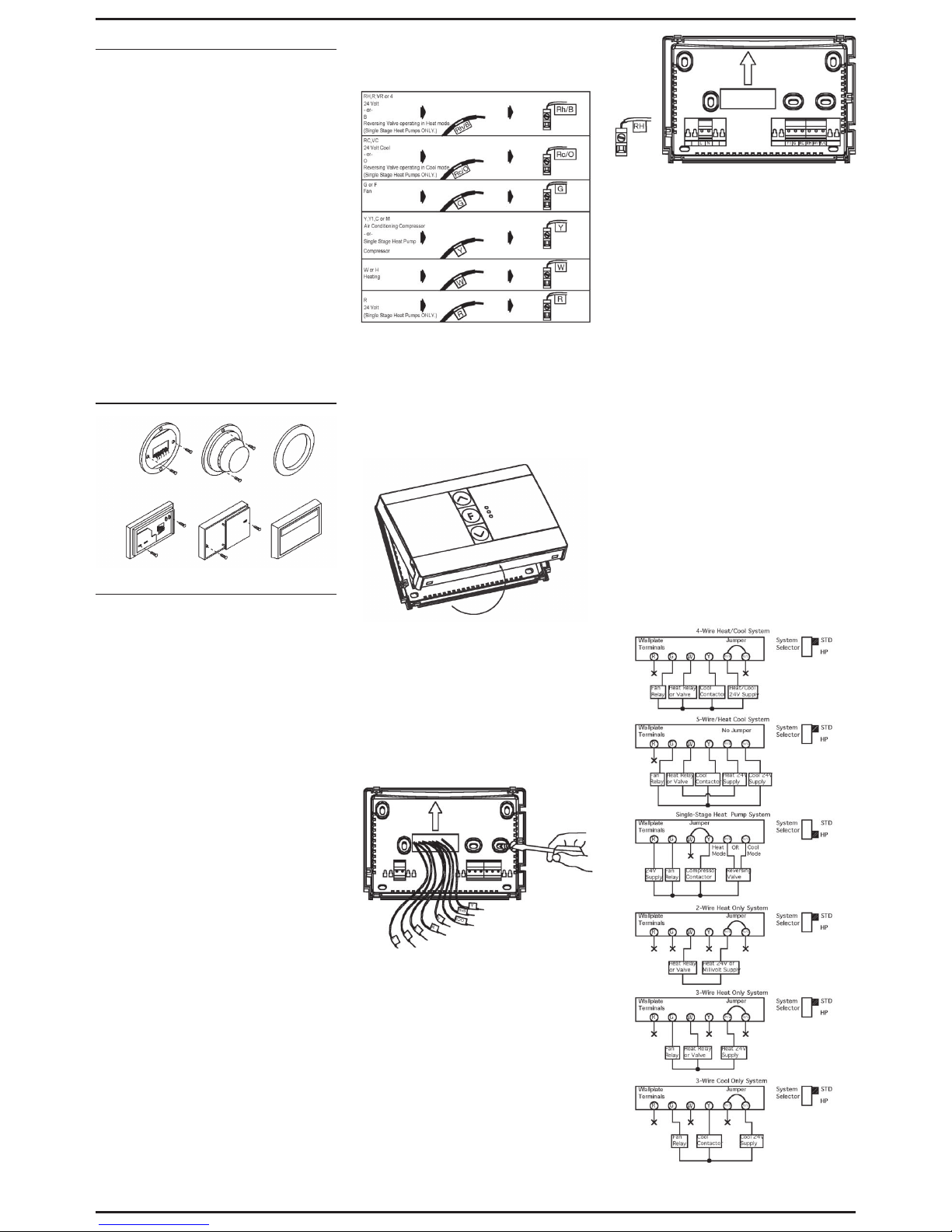
IMPORTANT INFORMATION
1. This thermostat is designed to work on the following
systems:
• Gas – Standing Pilot • Oil – Fired Furnace
• Gas – Electronic Ignion • Single Stage Heat Pumps
– with no auxiliary heat
• Gas – Fired Boilers • Electric Furnace
• Gas – Millivolt Systems • Electric Air Condioning
• Oil – Fired Boilers
This thermostat will NOT control mulstage heat pumps or
110/220V baseboard electric heang systems.
2. Temperature Range
This thermostat can be set between 45°F and 95°F (7°C
and 35°C). However, it will display room temperatures
from 30°F to 99°F (0°C and 37°C). HI will be displayed if
the temperature is higher than 99°F (37°C), and LO will be
displayed if the temperature is lower than 30°F (0°C).
This thermostat will automacally shut down in Heat
mode if the temperature rises above 95°F (35°C), and will
automacally shut down in Cool mode if the temperature
drops below 45°F (7°C).
3. Compressor Protecon
This thermostat provides a 4 minute delay aer shung
o the compressor before it can be restarted. This feature
will prevent damage to your compressor caused by rapid
cycling. It does not prevent a rapid compressor restart due
to short power outages.
4. Baery Warning
Two fresh AA alkaline baeries should provide well over
one year of service. However, when the baeries become
weak the Low Baery Indicator will ash on the display.
When this message occurs, install new alkaline baeries.
You have approximately 1 minute to change the baeries
and keep the thermostat’s sengs. Once the baeries
have become too weak to ensure proper operaon, your
system will be turned o, and the display will be cleared
except for a ashing Low Baery Indicator on the LCD
display.
CAUTION: When only the baery icon ashes on the
display, the thermostat is shut down, and your system
will no longer operate. In this condion, there is no
temperature control.
NOTE: The backlight will not funcon when the thermostat
is in low baery condion.
NOTE: If you plan to be away from the premises over 30
days, we recommend that you replace the old baeries
with new alkaline baeries prior to leaving.
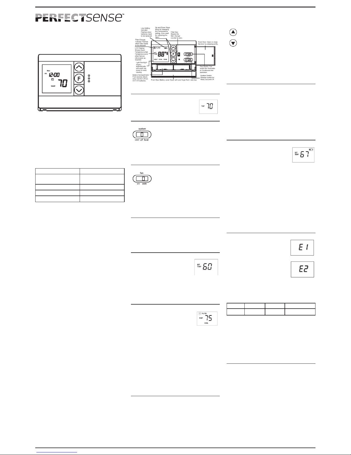
by Uni-Line®
FEATURES
Structure of thermostat and explanaon of the keypads
OPERATION
Start-up
The LCD will show the factory default
display of 70°F (21°C) when baeries
are rst installed. The temperature will
update aer a few seconds.
System Switch
The System switch on the front of the
thermostat determines the operang
mode of the thermostat. You may select
COOL, OFF, or HEAT.
NOTE: Anyme you install or remove the thermostat from
the wallplate, slide the System switch to the OFF posion
to prevent the possibility of a rapid system On – OFF.
Fan Switch
The Fan switch should normally be set in
the AUTO posion. The Fan will turn on
during normal operaon of your system.
In a normal gas or oil furnace, the Fan
will turn aer the furnace warms up. For electric heat, air
condioning, and heat pump operaon, the Fan will turn
on with the system.
To run the Fan connuously, slide the Fan switch to the
ON posion.
Review Current Set Temperature
• Press either the up or down key once to see the Set
Temperature.
The factory default is 68°F (20°C) when started with the
System switch on O or Heat, and 78°F (26°C) when
started with the System switch on Cool.
Seng New Temperature
• Press either up or down once to
display the set temperature.
• Press either up or down again
to change to your desired Set
Temperature. Hold the key down for over 2 seconds to
fast advance the Set Temperature.
The display will return to the normal room temperature
aer the keys have been released for 5 seconds.
Filter Monitor
The thermostat counts the number
of hours your system’s lter has been
in use. To maximize your system’s
performance and energy eciency,
change or clean your lter regularly.
When the total system run me for heat and cool reaches
400 hours, the Filter Change Indicator will ash as a
reminder to check your system’s lter.
Aer changing or cleaning the system lter, press and
release the Filter Buon. The usage hours will display on
the screen. Reset the display by pressing and holding the
Filter Buon again unl the hours displayed are zero (0).
Note: Pressing the Filter key at any me for less than 3
seconds will cause the Filter Change Indicator to appear
on the LCD. This is only to conrm key operaon. The
counter is not aected unless the key is held for 3 seconds
or longer.
DIFF Seng
Your thermostat is set at the factory to cycle at 2°F (1°C)
above and below the set temperature (DIFF = 2). This
seng has been designed to provide a comfortable room
temperature under most condions. However, if you nd
your system cycling too fast or too slow, then the DIFF can
be adjusted to modify the cycle me.
• Press and hold BOTH up and down keys for three
seconds. DIFF will be displayed on the LCD.
• Press up to raise the DIFF to 3. This seng
INCREASES the me between cycles by
allowing your system to run LONGER.
• Press down to lower the DIFF to 1. This
seng DECREASES the me between cycles
by causing your system to run SHORTER.
The DIFF sengs remain the same for both HEAT and
COOL, and can be changed in any System Switch posion.
When baeries are installed in the thermostat, the DIFF is
reset back to seng 2.
Backlighng
Your thermostat has an electroluminescent lamp that
backlights the display for easy viewing in the dark. When
any key is pressed, the display is illuminated.
The display will remain illuminated for 7 seconds aer the
last key is pressed. This allows the light to stay on if you
need to operate several keys.
Note: If the thermostat is in the Low Baery warning
condion, the backlight will not operate. Replace with 2
new AA alkaline baeries to restore the backlight funcon.
Low Baery Warning
Your thermostat has a two-stage low
baery warning system. When the
baeries are rst detected to be weak,
the rst stage low baery warning is
indicated by a baery symbol ashing
on the LCD display. Replace the baeries with 2 new
AA alkaline baeries. When the baeries become too
weak for normal operaon, the thermostat enters the
second stage low baery warning which shuts down the
thermostat. In this condion, the baery symbol ashes
alone on the display and the thermostat will turn your
system o. Your system will remain o unl the baeries
are replaced.
Note: The thermostat will sll keep the current set
temperature and lter run me in memory unl new
baeries are installed. Aer conrming that new baeries
have been inserted, the thermostat will return to normal
operaon.
Error Mode
If the thermostat is unable to control
your system due to an unexpected
baery problem, the thermostat will
enter Error Mode. In this condion, the
thermostat ashes E1 or E2 on the LCD
display, and shuts o your system.
To correct this problem, replace the
baeries with 2 new AA alkaline
baeries, even if you have recently
replaced them. Next, remove the baery, hold any key,
then replace the baery again. You will need to reprogram
your thermostat and conrm normal operaon. If Error
Mode returns, please call us for further informaon.
LCD Display Informaon LCD Display Informaon
E1 Sensor Error E2 System Switch Error
Auto Cut O
Your thermostat will automacally shut down in Heat
mode if the room temperature rises above 95°F (35°C).
It will shut down in cool mode if the room temperature
drops below 45°F (7°C).
Note that if your system has malfunconed and no longer
responds to thermostat controls, the Auto Cut-O will have
no eect.
Mechanical Heat Backup
This thermostat includes a bimetal switch that will
automacally turn on the Heat when the temperature
reaches about 41°F (5°C). WARNING: This switch only
acvates the heang terminal (W). The system itself must
be capable of automacally turning the fan on. Without
normal fan operaon, severe damage to the heang
system could result.

INSTALLATION
What You Need
This thermostat includes two #8 sloed screws and two
wall anchors for mounng. To install your thermostat, you
should have the following tools and materials.
• Sloed screwdriver(s)
• Small Philips screwdriver
• Hammer
• Electric drill and 3/16” bit
• Two 1.5V (AA) size alkaline baeries (included)
Remove Old Thermostat
CAUTION: Do not remove any wiring from exisng
thermostat before reading the instrucons carefully.
Wires must be labeled prior to removal.
IMPORTANT! Turn o the power to the furnace at the
main power panel or at the furnace.
Remove exisng thermostat cover and thermostat. Some
thermostats will have screws or other locking devices that
must rst be removed. Once the wall mounng plate is
exposed, look for wires. If wires are not visible, they may
be connected to the back of the wallplate. Again, look for
screws, tabs, etc. Some models have doors that open to
expose wires and mounng screws. See Figure 1.
Typical Home Thermostats
Figure 1
Wiring Labeling
• Each wire coming from the wall to the exisng
thermostat is connected to a terminal point on that
thermostat. Each of these terminal points is usually
marked with a code leer as shown in Table A.
• Note this thermostat has mulple funcon terminals
that allow single stage heat pump capability. Standard
systems use: Rh, Rc, G, Y, W. Single stage heat pumps
use: R, Y, G, and O or B. Table A shows the mulple
funcons of the terminals. Use the terminals that match
your system.
• The number of wires in your system can be as few
as two (for heat only systems), as many as eight, or
any number in between. If you follow the labeling
procedures correctly, you do not have to be concerned
about how many wires there are.
• There is oen no terminal marking on the exisng
thermostat of two wire, heat only systems. Just connect
either of the wires to the RH terminal, then connect the
other wire to the W terminal to complete the circuit.
• IMPORTANT! BEFORE DISCONNECTING ANY WIRES,
APPLY THE PROVIDED SELF-ADHESIVE LABELS TO THE
WIRE AS SHOWN IN TABLE A. (For example, aach the
label marked W to the wire that goes to the W or H
terminal on your exisng thermostat.) IGNORE THE
COLOR OF THE WIRES since these do not always comply
with the standard.
• Aer labeling wires, disconnect them from the exisng
thermostat.
• Remove exisng wallplate. To make sure wires do not
fall back into wall opening, you may want to tape them
to the wall.
• If the hole in the wall is larger than necessary for wires,
seal this hole with insulang material so that no hot or
cold air can enter the back of the thermostat from the
wall. This could cause a false thermostat reading.
Table A
If the code Then mark the wire And connect to
leer on your exist- with label shown thermostat terminal
ing thermostat is: shown
NOTE: Do not connect a Common wire (somemes labeled
C) to any terminal on this thermostat. Tape up the wire and
do not use it. This wire provides electricity to non-baery
powered thermostats.
Mount wallplate and Thermostat
• Remove the wallplate from your thermostat by pressing
the release tab on the boom of the thermostat. See
Figure 2.
Figure 2
• Posion wallplate on wall and pull exisng wires
through large opening. Then level for appearance. Mark
holes for plasc anchors provided if your exisng holes
do not line up with those on the wallplate.
• Drill holes with 3/16” bit and gently tap anchors into the
holes unl ush with wall.
• Reposion wallplate to wall, pulling wires through large
opening. Insert mounng screws provided into wall
anchor and ghten. See Figure 3.
Figure 3
NOTE: 5-Wire Systems
If your thermostat has one wire marked R or Rh (2, 3,
or 4-wire system), then leave the jumper wire between
the Rh and Rc terminals on the wallplate. Otherwise, if
you have separate Rh and Rc wires (5-wire system), then
remove the jumper wire between the Rh and Rc terminals.
Connect Wires and Mount Thermostat to Wallplate
• Match and connect the labeled wires to the appropriate
coded terminal screws on the wallplate. See Figures
4 and 5. Ignore any wires which may be present, but
which were not connected to the old thermostat.
Figure4 Figure 5
• Refer to the Wiring Diagrams below to be sure your
system is wired correctly.
• If your system is a single stage heat pump and uses an
O or B wire, you must move the System Selector switch
inside the thermostat to the Heat Pump posion. If
you have a normal furnace or electric system, leave
the switch in the Standard posion. Refer to the Wiring
Diagrams and System Selector secon below for more
informaon on this switch.
• Be sure to ghten the terminal screws securely,
otherwise a loose wire could cause operaonal
problems with your system or thermostat.
• Push excess wire back into the hole to prevent
interference when installing the thermostat to the
wallplate.
• Make sure the System switch is set to OFF, and the Fan
switch is set to AUTO.
• Insert the tabs on top of the thermostat body into the
slots at the top of the wallplate. Snap the boom of the
thermostat body into the boom of the wallplate. Refer
to Figure 2. (NOTE: Do not force the thermostat onto
the wallplate, as the terminal pins may be damaged. If it
does not snap properly, the thermostat may not work.)
• Insert the two AA size alkaline baeries, observing the
polarity marked inside the baery compartment.
• Switch on the main power at the panel or furnace.
Wiring Diagrams
X-No Connecon

Selector Switches
For this thermostat to control your system, the system
type must be specied by the selector switches on the
printed circuit board inside the thermostat. There is also
a selector switch for your choice of Fahrenheit or Celsius
temperature display. See Figure 6.
• Heang System Selector (HG – HE switch)
The factory posion for this switch is the HG posion.
Leave it in this posion if you have a gas furnace or an
oil burner. If you have an electric furnace, test to see
whether the heat and fan come on as expected aer
installaon. If the fan operaon is normal, leave it in
the HG posion. If the fan does not come on within a
minute of the thermostat calling for heat, change the
switch posion to HE. The system selector has no
eect in the cooling mode. NOTE: HG is for gas and
most other systems. HE is for certain electric systems
having a fan relay.
• System Selector (STANDARD – HEAT PUMP switch)
The factory posion for this switch is in the STD
posion. Leave it in this posion if you have ANY
system that uses gas, oil, electric, or hot water heang.
If you have a single stage heat pump (no auxiliary or
emergency heat source), then slide the switch to the
HP posion. Be sure the reversing valve wire is
connected to the correct terminal for your heat
pump (Rc/O) or (Rh/B).
• F° / C° selector (Fahrenheit - Celsius switch)
Your thermostat is set for F° mode from the factory.
To change to C° mode, slide the switch to C° and hold
any key for 2 seconds with the baery removed, then
replace the baery.
Figure 6
Two Year Limited Warranty
Robertshaw warrants to the original contractor installer or
to the original consumer user that each new PerfectSense
Product shall be free from defects in materials and
workmanship under normal use and service for a period
of two (2) years from the date of manufacture (“Warranty
Period”). If any Product fails within the applicable Warranty
Period, Robertshaw shall, at its sole opon, repair or
replace the Product, provided that the Product is returned
to Robertshaw facility or designated agent within the
Warranty Period, with transportaon charges prepaid, and
that the Product, upon examinaon by Robertshaw, is found
to conform to this warranty. The above warranty does not
apply to: i) baeries; ii) improper installaon; iii) Products
that have been damaged, misused, neglected, mishandled,
or altered in any manner whatsoever, and/or; iv) defects or
damage that result from use of the Product in other than
its normal and customary manner or in any manner not
in accordance with Robertshaw recommendaons and/or
instrucons. Any and all costs of labor, thermostat removal,
or reinstallaon are not covered under this warranty and
shall be the sole responsibility of the consumer or installer,
as applicable.
THE FOREGOING WARRANTY IS IN LIEU OF AND
EXCLUDES ALL OTHER WARRANTIES, WHETHER VERBAL
OR WRITTEN, EXPRESS OR IMPLIED INCLUDING, EXCEPT
TO THE EXTENT PROHIBITED BY APPLICABLE LAW,
THE IMPLIED WARRANTIES OF MERCHANTABILITY
AND FITNESS FOR A PARTICULAR PURPOSE. IN NO
EVENT SHALL ROBERTSHAW BE LIABLE TO CONSUMER,
CONTRACTOR OR ANY THIRD PARTY FOR ANY
CONSEQUENTIAL, INCIDENTIAL, SPECIAL OR PUNITIVE
DAMAGES ARISING FROM OR RELATING TO USE OF
THE PRODUCT INCLUDING, BUT NOT LIMITED TO, LOSS
OF GOODWILL, LOSS OF PROFIT OR REVENUE, AND
PROPERTY DAMAGE, REGARDLESS WHETHER SUCH
LOSS OR DAMAGE IS BASED IN CONTRACT, WARRANTY,
TORT, NEGLIGENCE, STRICT LIABILITY, INDEMNITY,
PRODUCT LIABILITY, OR OTHERWISE AND EVEN IF
ROBERTSHAW HAS BEEN ADVISED OF THE POSSIBILITY
OF SUCH DAMAGES.
TROUBLESHOOTING
Problem Soluon
No display 1. Check baery connecons and
baeries.
2. Remove the baery and wait for
about 1 minute, then replace
baeries.
Enre display dims 1. Replace baeries.
Auto fan does not
turn on properly
1. Move HG/HE selector to correct
posion.
Heang or cooling does
not go on or o
1. Check that the System switch is
in the correct posion (HEAT or
COOL).
2. There may be as much as a
4-minute delay before the
system turns on – wait and check
(Compressor protecon delay).
3. Check your circuit breakers
and switches to ensure there is
power to the system.
4. Replace baeries.
5. Make sure your furnace blower
door is closed properly.
6. If your non-heat pump system
only uses 4 wires, be sure the
jumper wire is installed between
the Rh/B and Rc/O terminals.
7. Check the posion of the System
selector switch: Standard or Heat
Pump.
8. If you have single stage heat
pump, be sure the jumper wire
is installed between the Y and W
terminals.
Errac display 1. Remove the baery, hold any
key then replace the baery.
Reprogram.
Unit connues to operate
in the OFF posion
1. Replace unit.
Thermostat permanently
reads HI, LO, or Er
1. Replace unit.
If you experience any other problems, contact Technical Support
service at: [email protected] or (800) 445-8299.
Customer Service Telephone 1.800.304.6563
Customer Service Facsimile 1.800.426.0804
Robertshaw®, Uni-Line® and PerfectSenseTM are trademarks of Robertshaw,
its subsidiaries and/or affiliated companies. All other brands mentioned
may be the trademarks of their respective owners.
For Technical Service
Telephone 1.800.445.8299
www.uni-line.com
www.robertshaw.com
©2015 Robertshaw
10/15 –352-00237-001
Popular Thermostat manuals by other brands

Elnur Gabarron
Elnur Gabarron CTM20 Installation and use manual

Vimar
Vimar SMART HOME VIEW WIRELESS 02973 instructions

GSi
GSi HF Series owner's manual

Comet
Comet Z-Wave 700226 quick start guide

Mi-Heat
Mi-Heat Optima Wlan Classic manual

Jackson Systems
Jackson Systems Web Comfort Z-2000 Quick installation and start-up guide