INTRODUCTION
This owner’s manual is provided to ease assembly,
maintenance and use of your Prindle Catamaran. We
believe these instructions portray the simplest methods.
Do it our way the first time and learn from us. Then, if
you discover a better method, feel free to tell us about
it by faxing (714) 541-6643 or e-mailing pcat@perfor-
mancecat.com. You may see your idea appear in the
next edition of the owner’s manual.
We are sure you will enjoy your Prindle Catamaran and
hope that this manual will make your enjoyment easier
to come by.
Make sure you join the Prindle Class Association - it’s fun
and it’s free to any new owner of a Prindle Catamaran
($20 annually after the first year). You will receive the
Performance Sailor, our official class newsletter. This
newsletter contains feature articles, news and results of
regattas, photographs, timely tuning tips, special
announcements and contests. As a member of the
Prindle Class Association, you will also be entitled to
enter and participate in all of our Class sanctioned regat-
tas.
One design racing begins at the local fleet level leading
to regional qualifying regattas and culminates with the
Annual National Championship Regattas held in a differ-
ent region every year. Even if you are not a racer, join
the Prindle Fleet in your area. Our fleets have held such
fun events as watermelon hunts, hull flying contests,
group cruises, Prindle barge picnics and clinics. It’s
much more fun to share the joy of sailing a Prindle
Catamaran. If a fleet does not exist in your area - start
one! All you need is a few enthusiastic owners!
Make sure your dealer fills out and submits your war-
ranty card for your new boat. Not only does it validate
your warranty, but it will also automatically register you
as a member of the Prindle Class Association. If you
have purchased a used Prindle, please send us your sail
and hull numbers as well as your complete address.
Make sure to notify us when you move too, the
Performance Sailor does not get forwarded.
Keep in touch. We love to hear from our owners!
1800 East Borchard Avenue
Santa Ana, CA 92705
(714) 835-6416
(714) 541-6643 fax
www.performancecat.com
CONTENTS
SECTION I: ASSEMBLY
Preparation 3
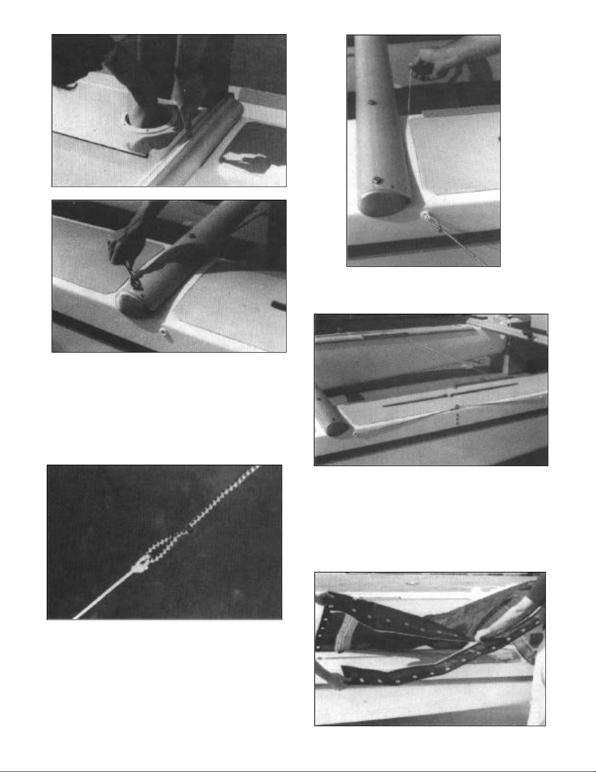
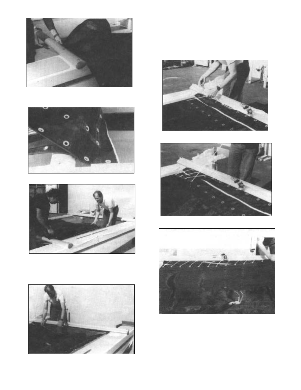
Crossbars 3
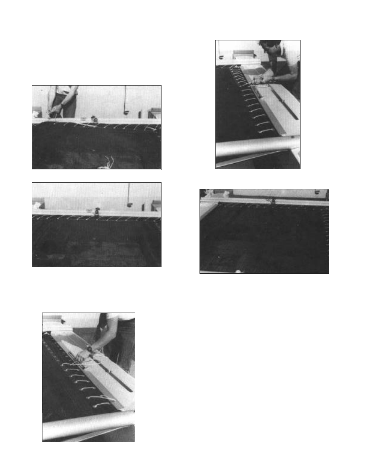
Trampoline 5
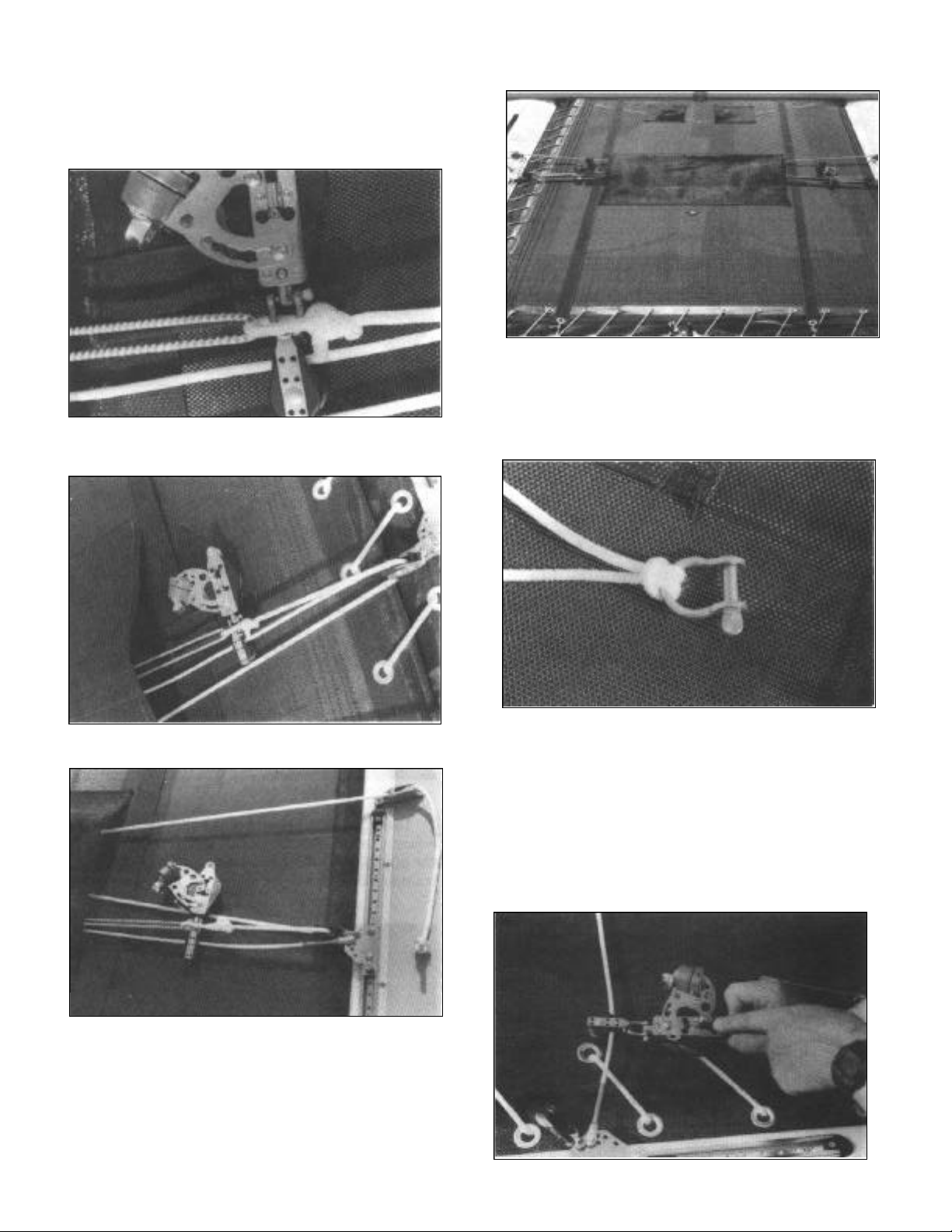
Standard Jib System 8
Deluxe 4-Way Jib System 8
Jib Sheet 10
Rudder System 11
Castings 11
Tiller Crossbar 11
Tiller Extension 11
Rudder Blades 12
Rudder Lock Bolt 12
Adjusting the Helm 12
Rudder Alignment 13
Operation of Rudder System 13
Mast and Rigging 14
Spreaders 14
Diamond Wires 15
Mast Rotator 16
Masthorn 16
Shrouds and Trapeze Wires 17
Forestay and Jib Halyard 17
Main Halyard 17
Raising the Mast 18
Diamond Wires 20
Sails and Battens 21
Mainsail Battens 21
Hoisting the Mainsail 22
Boom 23
Mast Rotator 23
Downhaul 23
Mainsheet and Traveler 24
Jib 24
Jib Sheet Jam Preventer 26
Righting Line 26
Tightening rig tension 26
Centerboard 27
SECTION II: SAILING
Sail Trim
To Weather 27
Reaching 28
Downwind 28
Downhaul Systems 28
Trapezing
Lacing the Harness 28
Trapeze Positioning 29
Launching
Onshore 30
Offshore 30
Tacking 31
Jibing 32
Balance 33
Righting 33
SECTION III: AFTER SAILING
Loosening the rig 36
Lowering the sails 36
Trailering 38
SECTION IV: MAINTENANCE
Dolphin Striker 40
Battens 41
Foam/Fiberglass Battens 41
General Maintenance Tips 41
Hulls 41
Rudders 41
Sails 42
Outhaul Systems 42
SECTION V: TUNING PERFORMANCE
Mast Rake 43
Mast Rotation 43
Barberhauler 43
SECTION VI: SUPPLEMENTAL INFORMATION
Major Parts of a Boat 44
Glossary of Terms 45
Knot Illustrations 46