Cal Boats CAL 27 Mk III User manual

Owner’s Manual

2
Contents
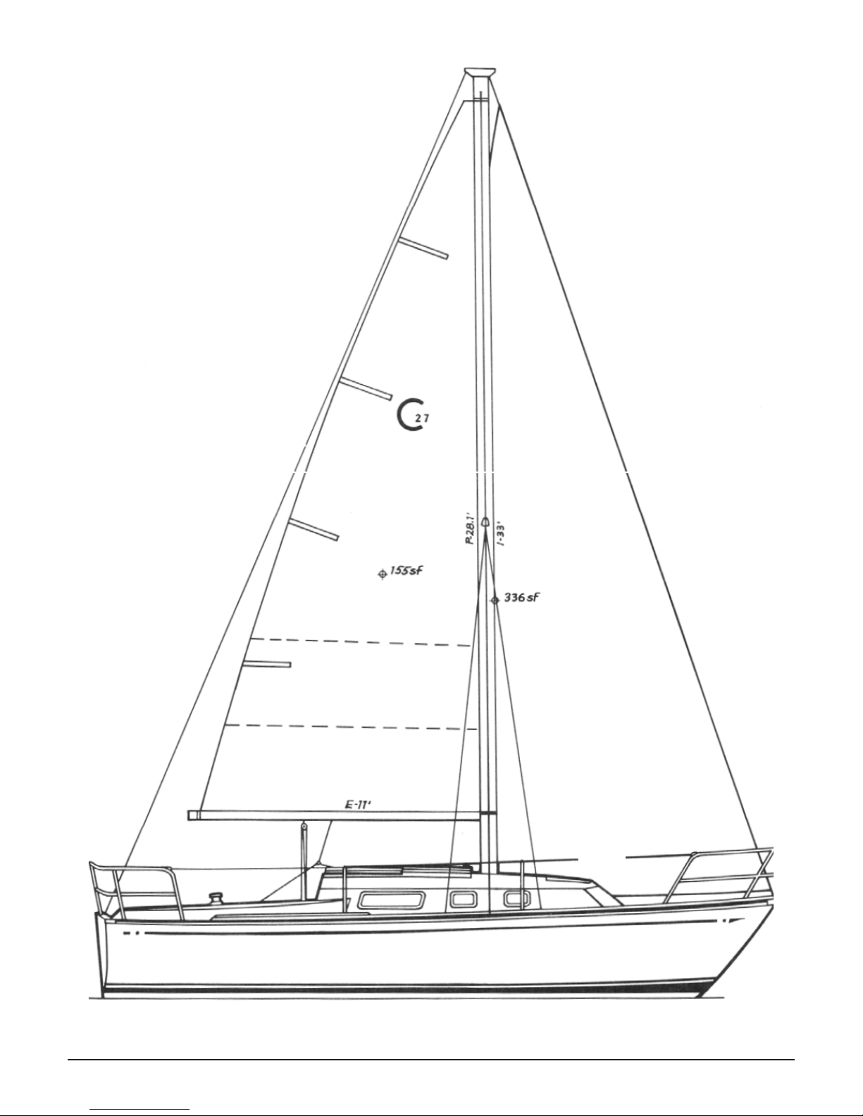
CAL 27 Mk III BOAT DIMENSIONS ............................................................4
COMMISSIONING ...............................................................................8
PRE-LAUNCH CHECK LIST........................................................................8
COMMISSIONING NOTES .....................................................................10
Note No.1.......................................................................................10
Note No.2.......................................................................................10
STEPPING AND TUNING THE MAST .........................................................11
RIGGING DIMENSIONS ........................................................................12
CAL 27 RUNNING RIGGING ...................................................................12
Wire Rigging....................................................................................13
BOAT STORAGE ................................................................................14
ENGINE OPERATING INSTRUCTIONS........................................................15
Alignment of Engine to Shaft ..................................................................15
Stung Box ....................................................................................16
FLOODING OF ENGINE WITH WATER............................................................16
Operator Error..................................................................................17
FUELING PROCEDURE.........................................................................19
ELECTRICAL.....................................................................................20
Master AC and DC Control Panels ..............................................................20
Circuit Breakers ................................................................................20
Battery Selector Switch ........................................................................20
CAUTION!.......................................................................................20
SHORE-POWER SYSTEM ......................................................................21
LIGHTNING GROUND..........................................................................23
NAVIGATION LIGHTS ..........................................................................24
We recommend: ................................................................................24
WATER SYSTEM ................................................................................25

3
COOKING STOVES & PROPANE STOVES ....................................................28
To Operate: .....................................................................................28
PLUMBING ......................................................................................30
THRU-HULL FITTINGS .........................................................................31
PERIODIC MAINTENANCE ....................................................................32
Maintenance Key ...............................................................................33
BASIC RULES FOR BATTERY CARE AND MAINTENANCE .................................34
FINISHES ........................................................................................36
Gelcoat .........................................................................................36
Teak ............................................................................................36
Laminated Surfaces ............................................................................37
Hull Liner and Cushion Covers..................................................................37
Lexan and Plexiglas ............................................................................37
Spars and Hardware............................................................................37

4 CAL 27 Mk III BOAT DIMENSIONS
CAL 27 MK III BOAT DIMENSIONS
HULL DIMENSIONS
LOA 26’8” 8.1 Meters
LWL 23’3” 7.1 Meters
Beam 9’0” 2.7 Meters
Draft 5’0” or 1.5 Meters or
4’0” 1.2 Meters
Displacement 5200 Lbs. 2364 Kilograms
Ballast 2000 Lbs. 907 Kilograms
RIG DIMENSIONS
I33’0” 10.06 Meters
J11’ 0” 3.35 Meters
P28’0” 8.53 Meters
E11’0” 3.35 Meters
100% Foretriangle 181.5 Sq.Ft. 16.86 Sq.M.
Mainsail Area 154.0 Sq.Ft. 14.31 Sq.M.
Total 335.5 Sq.Ft. 31.17 Sq.M.
Mast Height Above Water 36’4” 11.1Meters
MISCELLANEOUS
Berths
5
5
Fresh Water Capacity 22 Gallons 80 Liters
Ice Box Capacity 5.4 Cubic Ft. 153 Liters
Fuel Capacity 12.5 Gallons 47.5 Liters
Engine Diesel – Yanmar 7.5HP

CAL 27 Mk III BOAT DIMENSIONS 5
27' 9"
5'6"
3'3"
3'3"
1'11"
SLING
1'5" 1'5" 7" 27'9"
11'0"
5'0"
10'3"
5'0"
SLING
LIFT LIFT
BANGOR PUNTA MARINE
CAL 27-III
DOCKING PLAN
1-12-1983 JPF

6 CAL 27 Mk III BOAT DIMENSIONS

CAL 27 Mk III BOAT DIMENSIONS 7
BANGOR PUNTA MARINE
CAL 27-III
ARRANGEMENT
10-28-1982 JPF

8 COMMISSIONING
COMMISSIONING
Your Cal Yacht dealer will supervise the commissioning and testing of your new boat. His
knowledge and experience will insure that all systems and components will function properly
when the boat is delivered to you.
We have included some guidelines and instructions in this section to aid you and your
dealer.
PRE-LAUNCH CHECK LIST
1. All seacocks operational, closed, and tightened.
2. Accessory thru-hulls installed and tightened.
3. Diesel: Propeller in place; 2 nuts and cotter pin installed.
4. Zinc anodes installed on shaft.
5. Batteries secure, filled, and charged.
6. Rigging installed on spar; cotter pins spread and taped.
7. Masthead sheaves free to rotate; lubricated.
8. Mast lights working.
9. All required safety equipment on board.
NOTE: THIS IS A BASIC PRELAUNCH CHECK LIST.

COMMISSIONING 9
POST-LAUNCH CHECK LIST
1) All seacocks open and water tight.
2) Shaft aligned to .003” tolerance.
3) Engine shaft packing nut tightened. (See Stuffing Box under Engine Operation Instructions.)
4) Engine oil levels checked.(Refer to Engine Manual.)
5) Fuel tank filled and system checked for leaks.
6) Engine operates and passes water thru exhaust.
7) Engine controls operate correctly and checked for tight nuts, bolts, and spread cotter pins.
8) Mast stepped and mast collar installed. (Collar on Cal 35 and Cal 39 only.)
9) Mast bolted to mast collar ears.*
10) Turnbuckles attached; cotter pins spread and taped.
11) Boom and running rigging installed.
12) Water tank filled. (See Note 2 – Water Heater.)
13) Faucets work and lines checked for leaks.
14) Stove fuel tank filled; system checked for leaks. (Refer to Propane Stove Instructions, if applica-
ble.)
15) Electrical equipment operational. (See Note 1 for Shore-Power System.)
16) Steering gear operational.
17) Rudder shaft greased.
18) Bilge pump operational.
19) Toilets operational; hoses secure.
20) Deck hardware checked for leaks.
21) Warranties and manuals delivered to owner.
(After first light-air sail. See Instructions.)*

10 COMMISSIONING NOTES
COMMISSIONING NOTES
Note No.1
If your Cal Yacht is supplied with a 110V AC shore-power system, it will have a control panel
with a main breaker (30 amp) and separate (15 amp) breaker switches for the outlets and
water heater. In addition, there are both audible (buzzer) and visual (yellow light on panel)
reverse-polarity indicators. With all switches off, attach the power cable to the power inlet on
the boat. Next, connect the power cable to the dockside outlet. It is recommended that any
appliances used on board be wired with three-wire grounded plug.
WARNING: IF THE POLARITY INDICATORS LIGHT AND/OR SOUND, DISCONNECT THE
CORD IMMEDIATELY. THIS INDICATES A REVERSE POLARITY SITUATION WHICH IS
DANGEROUS. SEVERE INJURY OR DEATH MAY RESULT. DIAGNOSE AND CORRECT THE
PROBLEM BEFORE PROCEEDING.
Note No.2
If your Cal Yacht is equipped with a water heater, it will be installed to operate off both the
engine cooling system and the 110V AC electric system. Before switching the 110V system on,
be sure the water-heater tank is filled. Open the valve in the inlet water line, and be sure the
check valve is installed with the arrow pointed toward the water heater. Operate the pres-
sure-water system until you get a steady stream through the hot-water faucets.
WARNING: FAILURE TO FILL THE WATER HEATER BEFORE SWITCHING ON THE 110V
CIRCUIT WILL RESULT IN DAMAGE TO THE HEATING ELEMENT.

STEPPING AND TUNING THE MAST 11
STEPPING AND TUNING THE MAST
Before stepping the mast, be sure all running and standing rigging is properly installed,
cotter pins are spread, and halyard sheaves are free to rotate. The upper shroud is run through
the groove in the outboard end of the spreader; on either side of the groove is a hole. Through
these holes run a stainless wire. Wrap it around the stay several times in such a manner as to
prevent the shroud from jumping out of groove. After the shroud is wired in place, tape over
all the wire to protect the sails, and to prevent the wire from unraveling. Check the spar lights
to be sure they are operational. Open all turnbuckles to their full extension.
Cal 35 and Cal 39: Refer to Separate Sheet for Mast-Collar Instructions.
Step the spar through the deck and table (if applicable), and then on to the mast step. Be
careful not to pinch the mast wires during the stepping. (Cal 35 and Cal 39 – The mast step
was set at the factory to provide an aft rake. If you wish to adjust this, loosen the mast-step
bolts and slide the step fore or aft.) Attach all the shrouds; tighten the headstay, backstay, and
upper shrouds to a taut condition.
For now, leave the lower shrouds slack. Adjust the headstay and backstay to achieve a
straight spar, when sighting up the trailing edge. Next, with the boat level athwartship,
tighten the upper shrouds to get the mast straight. Finally, tighten the lowers no more than
hand tight.
Final tuning must be accomplished while sailing. In a light breeze (6–8 knots) adjust the
shrouds to achieve a straight spar on either tack. In heavier winds, any curvature should be
gradual and constant from the deck to the mast head. After the initial sail, go below, and drill
through the spar and install the bolt that passes through the mast collar ears and spar (Cal
35 and Cal 39). This serves to hold the deck from flexing and should not be installed until
the boat has been sailed and the rig tuned, to assure proper location of the hole. The rig will
need adjustment after a few sails to compensate for the stretch in the wire. Be sure to install
cotter pins in all turnbuckles and clevis pins, and tape over them to prevent injury to crew or
damage to sails. Fine tuning for the best performance will depend upon your local conditions
and your sails. Consult your dealer or local sailmaker for their suggestions.
WARNING: WHEN HAULING, LAUNCHING, AND SAILING NEAR LOW OVERHEAD WIRES,
CARE MUST BE TAKEN THAT THE MAST NOT COME IN CONTACT WITH SUCH WIRES.
CONTACT COULD CAUSE THE MAST TO CONDUCT ELECTRICITY AND CAUSE INJURY OR
DEATH.

12 RIGGING DIMENSIONS
RIGGING DIMENSIONS
The following table shows the critical dimensions and materials used for the standing and
running rigging on your Cal yacht. In the event you should need to replace any of the rigging,
you can order the materials through your Cal dealer. If this is not convenient, this table will
allow you or a local rigger to obtain the proper materials.
The standing rigging measurements are the overall length of the stay, from the center of
the hole in the upper terminal to the end of the swaged stud.
If using a different turnbuckle than supplied by Bangor Punta Marine, be sure to allow for
possible length difference. We would strongly recommend actually measuring any standing
rigging before replacing, to assure 100% accuracy. All running rigging should be checked peri-
odically for chafe or damage and replaced, when necessary.
If excessive wear is noted on running rigging, check all blocks and sheaves to be sure
they are free to rotate and are properly aligned. All standing rigging should be inspected for
cracks in the swages, proper installation of cotter pins, and wear on clevis pins. Replace any
damaged or suspect rigging. As you may have noticed on some sailboats the swaged ends of
the shrouds will ooze rust, and in severe cases, the swage will split. One way to prevent this
problem is to heat up the swaged section and place a bar of beeswax against the 1 x 19 stain-
less steel wire.
As it melts, the beeswax will run into the swaged section, sealing it from the elements.
CAL 27 RUNNING RIGGING
ITEM LENGTH DIAMETER MATERIAL FITTING
Main Sheet 45’ 7/16” Yacht Braid
Jib Sheet 37’6” 7/16” Yacht Braid
Main Halyard
Rope 39’6” 3/8” Yacht Braid Halyard Shackle
Wire 31’5” 1/8” 7 x 19 SS Cable
Jib Halyard
Rope 39’6” 3/8” Yacht Braid
Wire 36’3” 1/8” 7 x 19 SS Cable Snap Shackle
Reef Line 20’ 5/16” Yacht Braid
Outhaul 14’ 1/4” Yacht Braid Eye Splice One End
Boom Topping Lift
Mast 29’6” 1/4” Pre-stretch Yacht
Braid
Eye Splice Upper-
End-Bullet Block on
Lower End
Boom 10’ 1/4” Yacht Braid Eye Splice One End
Note: Main and Jib Halyards are wire-to-rope spliced.
Dimensions given are before splicing. Splice length is 1’8”.

Wire Rigging 13
WIRE RIGGING

14 BOAT STORAGE
BOAT STORAGE
Whenever a boat is pulled from the water, for work or storage, care must be taken to
provide adequate and proper support of the hull. This is especially true of fin-keel sailboats.
It is not recommended that the weight of the boat be rested solely on the keel. Because of
the small area of the keel bottom, the localized loads on the hull in the area of the keel would
be severe, and could result in permanent damage to the shape or structure of the boat.
If poppets are used for support, they should be located so that the pads are under bulk-
heads, berth fronts or pan stringers, so that the load is dispersed (See Docking Plan).
Failure to properly position the poppets could result in hull depression. Be sure to use an
adequate number of supports, and locate them to prevent the boat from tipping fore or aft. A
storage cradle designed for this boat is available through your Cal dealer.
When hauling any boat with a propeller shaft, be sure to disconnect the coupling before
lifting the boat. This will prevent bending of the shaft as the boat changes shape when lifted.
DO NOT CAREEN A FINKEEL SAILBOAT. THE HULL, KEEL, AND RUDDER SHOULD SURVIVE
ANY ACCIDENTAL GROUNDING. HOWEVER, CARE MUST BE TAKEN TO KEEP THE BOAT AS
BALANCED AND UPRIGHT AS POSSIBLE TO PREVENT EXCESSIVE LOADS.
WARNING: WHEN HAULING, LAUNCHING, AND SAILING NEAR LOW OVERHEAD WIRES,
CARE MUST BE TAKEN THAT THE MAST NOT COME IN CONTACT WITH SUCH WIRES.
CONTACT COULD CAUSE THE MAST TO CONDUCT ELECTRICITY AND CAUSE INJURY OR
DEATH.

ENGINE OPERATING INSTRUCTIONS 15
ENGINE OPERATING INSTRUCTIONS
The engine installed in your yacht has already been run and all systems tested before leav-
ing the Cal, plant. We are not going to get into a great amount of detail in this area, for we
believe the manual supplied by the engine manufacturer adequately covers the subject.
Study your engine owner’s manual and get to know your engine. The knowledge could
be of great assistance to you. Also, some manufacturers have clinics aimed at the customer;
contact them for details.
It is advisable that you follow the engine manufacturer’s procedures and recommendations
on run-in and maintenance. On yachts with propeller shafts, please use the following proce-
dure:
Alignment of Engine to Shaft
The engine must be properly and exactly aligned with the propeller shaft. No matter what
material is used to build a boat, it will be found to be somewhat flexible, and when launched,
the boat hull will change its shape to a greater extent than is usually realized. It is, therefore,
very important to check the engine alignment at frequent intervals and to correct any errors
when they appear.
Misalignment between the engine and the propeller shaft is the source of troubles which
are often blamed on other causes. It will create excessive bearing wear, rapid shaft wear, or
leakage of transmission oil through the rear seal. A bent propeller shaft will have exactly the
same effect, and it is, therefore, necessary that the propeller shaft itself be perfectly straight.
The engine should be moved around on the bed and supported on the screw mounts until
the two halves of the couplings can be brought together without using force and so that the
flanges meet evenly all around. Never attempt a final alignment with the boat on land. The
boat should be in the water and have had an opportunity to assume its final water form. It is
best to do the alignment with the fuel and water tank about half full and all the usual equip-
ment on board and after the main mast has been stepped and final rigging has been accom-
plished.
Take plenty of time in making this alignment, and do not be satisfied with anything less
than perfect results. The alignment is correct when the shaft can be slipped backward and
forward into the counterbore very easily and when a feeler gauge indicates that the flanges
come exactly together at all points. The two halves of the coupling should be parallel within
0.003 inches. In making the final check for alignment, the engine half coupling should be held
in one position and the alignment with the propeller coupling checked in each of four posi-
tions, rotated 90° between each position. This test will also check whether the propeller half
coupling is in exact alignment on its shaft. Then, keeping the propeller coupling in one posi-
tion, the alignment should be checked, rotating the engine coupling as described above.
The engine alignment should be re-checked after the boat has been in service for one to
three weeks and, if necessary, the alignment remade. It will usually be found that the engine is
no longer in alignment. This is not because the work was improperly done at first, but because
the boat has taken some time to take its final shape. It may even be necessary to re-align at a
further period. The coupling should always be opened up and the bolts removed, whenever
the boat is hauled out or moved from the land to the water and during storage in a cradle.
The flexibility of the boat often puts a very severe strain on the shaft or the coupling or
both when it is being moved. During the alignment procedure, check the set screws which

16 ENGINE OPERATING INSTRUCTIONS
hold the propeller half coupling to the shaft. These must be tight, in contact with the shaft,
and safety wired.
Stung Box
The stuffing box provides a seal for the propeller shaft at the inner end of the shaft log. It is
connected to the shaft log with heavy wall hose, double clamped at each end. This flex hose
allows the stuffing box to maintain alignment with the prop shaft without creating excessive
wear of the packing, due to misalignment or vibration. The packing used is wax impregnated
3/16” x 3/16” square flax.
When the shaft is turning, it is normal to have a slight leakage at the seal, about one drop
per 30 seconds. This acts as a coolant, as well as a lubricant, to protect the seal and shaft
surface. Should excessive leakage be apparent, release the lock nut and tighten the packing
nut slightly and re-tighten the lock nut.
Re-start engine and check again with shaft turning. When it becomes necessary to replace
the packing (boat should be hauled), loosen the lock nut, back off the packing gland nut, and
slide it forward on the shaft. Remove all the old packing and replace it with three rings of new
packing.
Stagger the ends of each ring so as not to provide a path for water to leak through. D o
not wind one continuous strip spirally around prop shaft to make a seal. Slide the packing
gland back and tighten enough to create a heavy drag on the shaft. This will seat and form the
packing. Back off the packing nut until the shaft feels free and re-set the lock nut. Re-check
for proper leakage when boat is returned to the water. Be sure the lock nut is secure, as oper-
ating the boat in reverse could cause the packing gland to screw off the stuffing box, allowing
water into the boat.
FLOODING OF ENGINE WITH WATER
Your Cal Yacht is supplied with a water-lift (wave suppressor) type of muffler that under
normal conditions, when the engine is not running, provides wave suppression and water
storage to help keep water from flooding the engine.
NOTE: THERE IS A DIRECT PATH FROM THE OVERBOARD EXHAUST PORT VIA THE
WATERLIFT MUFFLER TO THE ENGINE AND FROM THE WATER PUMP TO THE MUFFLER.
ACCIDENTAL CONDITIONS SEA AND OPERATOR ERROR PROLONGED STARTING
ATTEMPTS CAN THUS CAUSE AN EXCESSIVE VOLUME OF WATER TO FILL THE MUFFLER
AND FLOOD THE ENGINE.
UNDER SUCH ACCIDENTAL SEA AND/OR MISUSE CONDITIONS, ENGINE FLOODING MAY
BE UNAVOIDABLE.

ENGINE OPERATING INSTRUCTIONS 17
Sea Flooding
Your Cal exhaust system is designed and installed to the highest standards, and, as stated
above, could still flood under certain heavy sea conditions. The only added safety precaution
you could add would be to install a rubber flap to the overboard exhaust port. This would
dramatically slow the surge effect of waves hitting the port.
Operator Error
This is a nagging source of water-in-the-engine and occurs when an operator repeatedly
attempts to start an engine; i.e., he “grinds” the starter—not 2 or 3 times—but continually.
The amount of cranking time varies from engine to engine, factors being the amount of each
piston’s displacement, the water pump’s capacity, and whether the battery is cranking a full
R.P.M.

18 ENGINE OPERATING INSTRUCTIONS
BANGOR PUNTA MARINE
CAL 27-III
FUEL SYSTEM
(YANMAR 1GM 7.5 HP)
1-12-1983 JPF
Illustration Key
22 Engine diesel universal
23 Fuel pump on engine
24 Fuel line
25 Fuel return line
26 Fuel shut o valve
27 Fuel tank 12.5 gals
28 Fuel level sender
29 Fuel ll line
30 Fuel ll plate (port cockpit coming side)
31 Fuel tank vent line
32 FuelVent (port aft cockpit coaming)
33 Filter
1
23
4
56
87
9
11
10
12

FUELING PROCEDURE 19
FUELING PROCEDURE
A. When preparing to fuel your boat, the following procedures should be followed to assure
safety:
B. Properly secure the boat to the dock.
C. Turn off the engine, stove, heater, radio, lights, etc.
D. Turn the battery switch to OFF.
E. Close all hatches, ports, etc., to prevent entry of fumes.
F. Maintain continuous contact between the nozzle and deck plate to prevent a static charge.
G. Fill tank to a maximum 95% of capacity to allow for expansion.
H. Clean any spills after replacing and tightening fuel-fill cap.
Before operating the engine or turning battery switch to ON, open all hatches and check
for fuel leaks.
Always be sure the fuel-fill cap is tight, to prevent water and dirt from getting into the
fuel tank. Periodically check the fuel filter and water separator. Those should be drained
and cleaned, as needed. The filter elements should be replaced annually.

20 ELECTRICAL
ELECTRICAL
Master AC and DC Control Panels
The master electrical control panels are located on the aft bulkhead, behind the compan-
ionway stairs. The AC master panel includes circuits for a battery charger, the water heater,
and the port and starboard electrical outlets. The DC master and accessory panels handle all
other electrical systems.
Circuit Breakers
Accessory loads may be selected as desired by turning on the master-control panel circuit
breakers. The circuit breakers will automatically open the circuit by switching themselves to
“OFF” in the event of an overload on a particular circuit.
ALWAYS INVESTIGATE THE CAUSE OF THE OVERLOAD AND CORRECT ANY DEFICIENCIES
BEFORE REPOSITIONING THE CIRCUIT BREAKER TO “ON”.
ALL WIRES, CONNECTIONS, AND TERMINALS SHOULD BE INSPECTED REGULARLY FOR
LOOSE CONNECTIONS, WHICH MAY CAUSE ELECTRICAL SPARKS, HIGH RESISTANCE OR
FIRES. THIS IS ESPECIALLY IMPORTANT FOR ENGINE ACCESSORY WIRING.
Battery Selector Switch
Before leaving your boat, always turn the master-battery switch to the “OFF” position to
prevent power drainage. DO THIS ONLY AFTER YOU HAVE SHUT DOWN THE ENGINE, for you
may burn out the alternator diodes.
CAUTION!
You may switch from one battery to another for charging, but DO NOT pass through the
“OFF” position while the engine is running. This may burn out the alternator diodes. Keep the
engine RPM as low as possible, when switching batteries.
Table of contents
Other Cal Boats Boat manuals
Popular Boat manuals by other brands

Oru Kayak
Oru Kayak Beach LT Assembly and disassembly guide

Everglades
Everglades 210 CC 2012 owner's manual

VIRTUFIT
VIRTUFIT Supboard Ocean 305 user manual

Yamaha
Yamaha WaveRunner GP1300R Supplemental service manual

Clas Ohlson
Clas Ohlson 31-4283 instruction manual

Flexboat
Flexboat FLEX 450 Assembly instructions