Performance Travel Trac Club Cycle User manual

Table of Contents
Introduction . . . . . . . . . . . . . . . . . . . . . . . . .1
Safety Guidelines . . . . . . . . . . . . . . . . . . . .2
Parts List. . . . . . . . . . . . . . . . . . . . . . . . . . . .3
Assembly . . . . . . . . . . . . . . . . . . . . . . . . . . .3
Adjustment and Setup . . . . . . . . . . . . . . . .3
Moving and Leveling the ClubCycle. .3
Seat Adjustment . . . . . . . . . . . . . . . . .3
Handlebar Adjustment . . . . . . . . . . . .4
Toe Clip Strap Adjustment . . . . . . . . .4
Using the ClubCycle . . . . . . . . . . . . . . . . . .5
Maintenance . . . . . . . . . . . . . . . . . . . . . . . .5
Thank you for choosing the Travel Trac™
ClubCycle as part of your exercise program.
For years to come, you’ll be able to rely on
Travel Trac™quality and durability as you pursue
your fitness goals. The Travel Trac™ClubCycle is
designed to closely replicate the feel and aerobic
benefits of road cycling. Its unique design, fixed
gearing and a heavy flywheel produce a smooth,
intense workout. The ClubCycle and a regular
exercise program
should enable you to:
- Increase cardiovascular and aerobic fitness
- Increase lower body strength
- Decrease your overall percentage of body fat
- Boost your energy level
Whether you’re just starting an exercise
program or are already in good shape, the Travel
Trac™ClubCycle is designed to be an efficient,
challenging, and enjoyable way to achieve better
fitness and a slimmer, healthier body!
This Owner’s Manual contains all the information you need to assemble, adjust and use your Travel Trac™ClubCycle. Please
read the Owner’s Manual in its entirety before using your ClubCycle for the first time. Below are a few of the features that
make the Travel Trac™ClubCycle an excellent choice for reaching your fitness goals.
Seat Adjustment
Seat height and fore/aft position are easily adjustable. The anatomically designed seat comfortably supports various body
types for an effective workout at any intensity.
Multi-position Handlebar
Handlebar height and fore/aft position are easily adjustable to help fine tune the riding position. The coated bar offers multiple
hand positions to provide comfort and stability during seated or standing workouts.
Resistance Control Knob
Mounted within easy reach on the down tube, the resistance control knob allows you to adjust the intensity of your workout
by making incremental resistance adjustments on the fly. The control knob also operates the flywheel brake.
Smooth Action Flywheel
The 42 pound flywheel realistically simulates road riding at any RPM and facilitates smooth pedaling. The sealed bearing hub
ensures performance and durability.
33
34
34
33
32
9d
54
6
7
84
54
9b
5
13
30
3
32
14
29
29
63
64
2
9c
10
37
9a
24
head tube
seat tube
1
08_TravelTrac_ClubCycle_INS.indd2 2 7/3/08 2:20:07 PM

2
Quick Stop Brake System
The brake system allows the benefits of fixed gear riding—essential to many indoor
cycling workouts—with the built in safety of an instant braking feature.
Powder Coated and Chrome Plated Steel Construction
Heavy-gauge steel frame construction provides maximum stability, while the
powder coated finish and chrome plating provides durable corrosion resistance.
Quick-Adjust Knobs
Quick-adjust knobs control seat and handlebar height as well as fore/aft position,
making fit adjustments simple and fast.
Belt Drive
A durable, silent alternative to the traditional and noisier chain drive, the belt
drive provides a clean, quiet, smooth transmission of power from the pedals
to the flywheel.
Pedals
The pedals included with the Travel Trac™ClubCycle are dual sided. One side
functions as a standard platform pedal with toe clips and straps for use with athletic
shoes. The other side includes a clipless mechanism for use with cleated cycling
shoes. For more information about using the clipless side of these pedals, see page 6.
I.Parts List
Part Part Code Quantity
Front Base Tube. . . . . . . . . . . . . . . . . . . . . 2 . . . . . . . . . . . . . . . . . . . . . . 1
Rear Base Tube . . . . . . . . . . . . . . . . . . . . . 3 . . . . . . . . . . . . . . . . . . . . . . 1
Handlebar. . . . . . . . . . . . . . . . . . . . . . . . . . 4 . . . . . . . . . . . . . . . . . . . . . . 1
Handlebar Post . . . . . . . . . . . . . . . . . . . . . 5 . . . . . . . . . . . . . . . . . . . . . . 1
Seatpost . . . . . . . . . . . . . . . . . . . . . . . . . . . 6 . . . . . . . . . . . . . . . . . . . . . . 1
Seatpost Slider . . . . . . . . . . . . . . . . . . . . . 7 . . . . . . . . . . . . . . . . . . . . . . 1
Seat. . . . . . . . . . . . . . . . . . . . . . . . . . . . . . . 8 . . . . . . . . . . . . . . . . . . . . . . 1
Adjustment Handles . . . . . . . . . . . . . . . . . 9 . . . . . . . . . . . . . . . . . . . . . . 4
Resistance Control Knob. . . . . . . . . . . . . . 10 . . . . . . . . . . . . . . . . . . . . . . 1
Left Pedal . . . . . . . . . . . . . . . . . . . . . . . . . . 13 . . . . . . . . . . . . . . . . . . . . . . 1
Right Pedal. . . . . . . . . . . . . . . . . . . . . . . . . 14 . . . . . . . . . . . . . . . . . . . . . . 1
Flywheel . . . . . . . . . . . . . . . . . . . . . . . . . . . 24 . . . . . . . . . . . . . . . . . . . . . . 1
Before starting any exercise program, consult with your physician or health profes-
sional to establish exercise frequency, intensity and duration appropriate for your
age and physical condition. If you experience any pain or tightness in your chest,
an irregular heartbeat, shortness of breath, or feel faint while you exercise, STOP!
Consult your physician before continuing.
! WARNING
Failure to follow any of these safeguards may result in injury or serious
health problems.
• Keep feet on pedals while exercising. Do not remove feet from pedals while
pedals are in motion. Do not dismount until pedals and flywheel have come to
a complete stop.
• Use this equipment only for its intended purpose as described in this Manual.
Do not attempt to ride at a high cadence (high speed) or in a standing position
until you have practiced and are comfortable riding at slower pedal speeds.
• Keep hands away from all moving parts. Never turn pedal crank arms by hand.
To avoid entanglement and possible injury, keep hands and fingers away from
the drive mechanism.
• Keep children and pets away from the ClubCycle while in use.
• Warn bystanders to keep a safe distance. Do not allow bystanders to approach
the ClubCycle while it is in use and the pedals are in motion.
• After exercising, turn the resistance control knob clockwise (+) to increase
tension on the flywheel so the pedals cannot rotate freely.
! WARNING
08_TravelTrac_ClubCycle_INS.indd3 3 7/3/08 2:20:07 PM

Transport Wheels . . . . . . . . . . . . . . . . . . . 29 . . . . . . . . . . . . . . . . . . . . . . 2
Leveling Feet . . . . . . . . . . . . . . . . . . . . . . . 30 . . . . . . . . . . . . . . . . . . . . . . 4
Assembly Bolts . . . . . . . . . . . . . . . . . . . . . 32 . . . . . . . . . . . . . . . . . . . . . . 4
Assembly Washers . . . . . . . . . . . . . . . . . . 33 . . . . . . . . . . . . . . . . . . . . . . 4
Assembly Nuts. . . . . . . . . . . . . . . . . . . . . . 34 . . . . . . . . . . . . . . . . . . . . . . 4
Resistance Pad. . . . . . . . . . . . . . . . . . . . . . 37 . . . . . . . . . . . . . . . . . . . . . . 1
Adjustment Handle Washers . . . . . . . . . . 54 . . . . . . . . . . . . . . . . . . . . . . 2
Toe Clips. . . . . . . . . . . . . . . . . . . . . . . . . . . 63 . . . . . . . . . . . . . . . . . . . . . . 2
Toe Straps . . . . . . . . . . . . . . . . . . . . . . . . . 64 . . . . . . . . . . . . . . . . . . . . . . 2
Cleat Hardware . . . . . . . . . . . . . . . . . . . . . 65 . . . . . . . . . . . . . . . . . . . . . . 1 set
II. Assembly
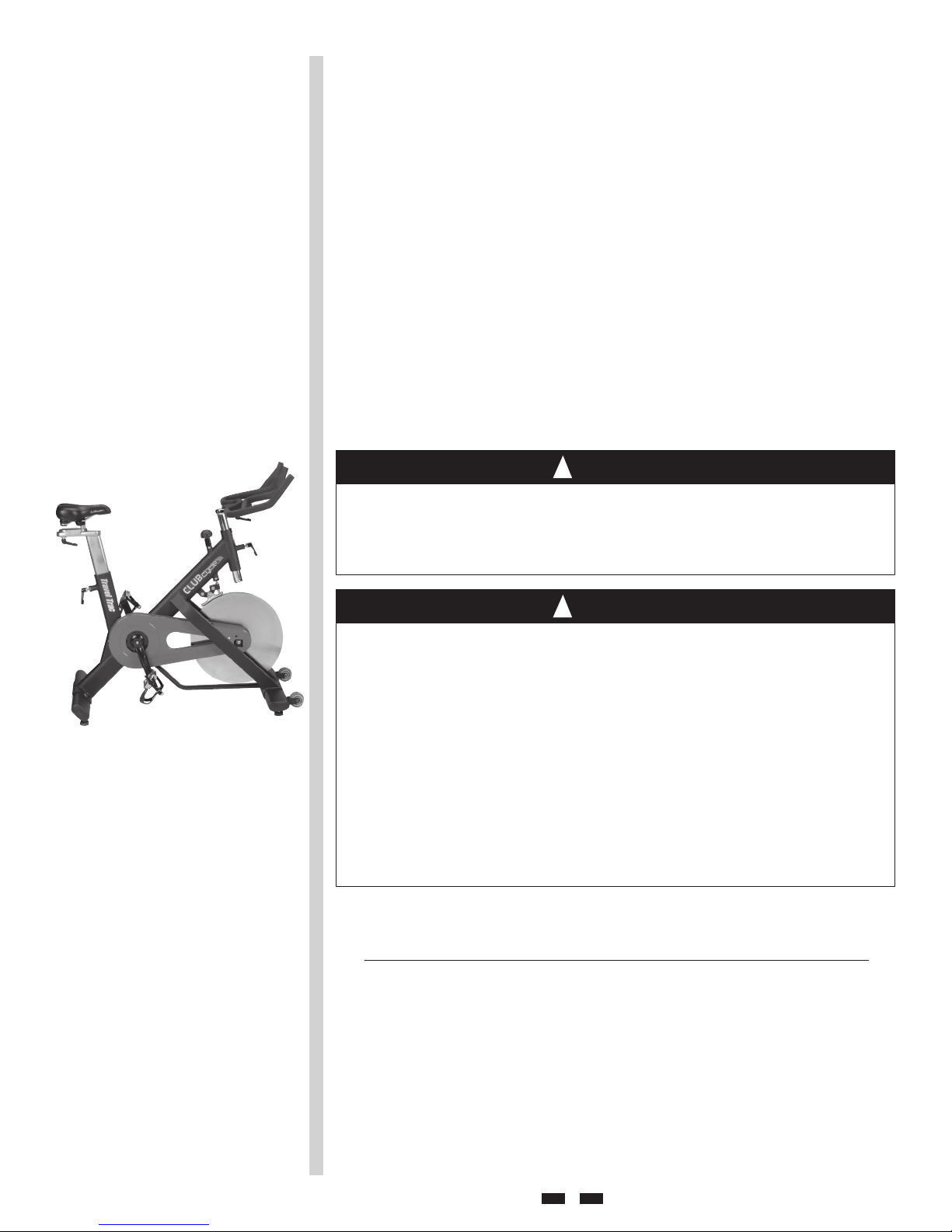
Your Travel Trac™ClubCycle exercise bike has been packed in two cartons.
1. Move the boxes to the desired location and ensure they are standing upright.
Open both boxes, remove the bike and other contents from the boxes and
dispose of packing material.
2. Use the assembly bolts (32), washers (33) and nuts (34) to attach first the rear
(3) and then the front (2) base tubes to the main frame as shown in Figure 1. The
wheels (29) on the front base tube should face forward (away from the bike).
3. Place the handlebar (4) on top of the handlebar post (5) as shown in Figure 1,
making sure that the thin plastic shim on the underside of the handlebar is in
place. Thread the adjustment handle (9b) with washer (54) into the hole on the
underside of the handlebar and tighten securely by turning it clockwise.
Note: The adjustment handle is spring loaded. If the handle strikes the handlebar
post while tightening it, pull on the handle and rotate it to a different position.
4. Slide the seat (8) onto the seat slider post (7) as shown in Figure 1. Point the nose
of the seat forward and tighten the seat bracket nuts securely (see Figure 2).
5. Install the pedals (see Figure 1). The left and right pedals are marked with “L”
and “R”. The right pedal (14) tightens in a clockwise direction. The left pedal (13)
is reverse threaded and tightens in a counter clockwise direction. Apply a small
amount of grease to the pedal axle threads before installation to simplify removal
in the future. Use the provided wrench tool to tighten both pedals securely.
6. If desired, a water bottle cage can be attached to each fork blade.
III. Adjustment and Setup
Moving your ClubCycle
If you didn’t assemble your ClubCycle in the location you plan to use it, you’ll need
to move it before beginning your first workout.
Make sure that the handlebar is securely attached to the bike and that the handlebar
adjustment handles (9a and 9b) are tightened securely. Standing in front of the
bike, grasp the ends of the handlebar. Place one foot on the front base tube (2) and
tilt the bike toward you until the transport wheels (29) are touching the floor (see
Figure 3). Roll the bike to the desired location and set the rear of the bike back down
on the floor slowly and carefully.
Leveling the Unit
The ClubCycle can be leveled to compensate for uneven floor surfaces. To level the
bike, raise or lower the four leveling feet (30) located on the underside of the front
and rear base tubes.
Seat Adjustment
Proper seat position helps ensure maximum exercise efficiency and comfort, while
reducing the risk of injury. To raise or lower the saddle and move it forward or
backward, follow the steps below.
Seat Height
1. To determine proper seat height, sit on the ClubCycle in your normal exercise
clothing and shoes. Rotate the pedals so that one is at the 12 o’clock position and
the other is at the 6 o’clock position (see Figure 4).
2. Place your feet on the pedals with the ball of each foot over the center of each
pedal. In this position, your extended leg should be slightly bent at the knee (see
Figure 4).
3
2
4
3
08_TravelTrac_ClubCycle_INS.indd4 4 7/3/08 2:20:08 PM

6
3. If there is no bend in your knee or you cannot touch the pedal, you will need to
lower the seat. If the bend in your knee is too severe, you will need to raise the seat.
4. Dismount, and loosen the height adjustment handle (9c) at the top of the seat
tube by turning the handle counterclockwise (see Figure 5). Raise or lower the
seat to the desired position and securely tighten the adjustment handle by turning
it clockwise. Note: The adjustment handle is spring loaded. Once tightened, make
sure it does not stick out to the side of the seat tube. Pull on the handle, rotate it
to the proper position and release it.
Fore-Aft Position
1. Sit on the bike as you did while adjusting seat height.
2. Rotate the pedals so that they are at the 3 o’clock and 9 o’clock position.
3. Drop a plumb line from the knee of your forward leg, with the top of the plumb
line placed in the depression next to your kneecap.
4. Observe where the bottom of the line falls. It should touch your foot at a point
that bisects the pedal axle.
5. If the line falls in front of the pedal axle, you should move the seat back slightly. If
it falls behind the axle, you should move the seat forward slightly.
6. Dismount, and loosen the adjustment handle (9d) below the saddle by turning
the handle counterclockwise (see Figure 6). Slide the seat forward or backward
to the desired position and securely tighten the adjustment handle by turning it
clockwise. Note: The adjustment handle is spring loaded. If the handle strikes the
seatpost while you’re trying to loosen or tighten it, pull on the handle and rotate it
to a different position.
7. Adjustments can also be made by sliding the seat forward or backward in the seat
bracket. Use an adjustable wrench or a 14mm socket wrench or spanner to loosen
the nuts on each side of the saddle clamp (see Figure 2). Slide the saddle forward
or rearward as desired and securely retighten the clamp nuts.
Seat Angle
1. Begin by positioning the seat so that it’s parallel to the ground.
2. Using an adjustable wrench or a 14mm socket wrench or spanner, loosen the
nuts on each side of the saddle clamp (see Figure 2). Place a straightedge or
level along the top of the seat and raise or lower the nose of the saddle until the
straightedge is parallel to the ground.
3. From this point, the nose of the seat can be angled slightly upward or downward
according to personal preference.
4. Once the angle is adjusted to suit your preference, securely retighten the seat
clamp nuts.
Handlebar Adjustment
The handlebar can be raised or lowered and moved forward or backward to achieve
a comfortable riding position. To adjust handlebar position, follow the steps below.
Handlebar Height
1. To raise or lower the handlebar, loosen the height adjustment handle (9a) on the
head tube by turning the handle counterclockwise (see Figure 7).
2. Raise or lower the handlebar to the desired position. This will be easier if you
rotate the handlebar side to side slightly as you raise or lower it. Once the
handlebar is at the desired height, securely retighten the adjustment handle
by turning it clockwise. Note: The adjustment handle is spring loaded. Once
tightened, make sure it does not stick out to the side of the head tube. Pull on the
handle, rotate it to the proper position and release it.
Do not raise the seatpost beyond the “Max” mark printed on the post.
Doing so may lead to post failure, resulting in serious injury.
! WARNING
7
8
44
5
Do not raise the handlebar post beyond the “Max” mark printed on the post. Doing
so may lead to post failure, resulting in serious injury.
! WARNING
08_TravelTrac_ClubCycle_INS.indd5 5 7/3/08 2:20:08 PM

10
–+
10
Fore-Aft Position
1. To move the handlebar forward or backward, loosen the adjustment handle (9b)
below the handlebar by turning it counterclockwise (see Figure 8).
2. Slide the handlebar forward or backward to the desired position and securely
retighten the adjustment handle by turning it clockwise. Note: The adjustment
handle is spring loaded. If the handle strikes the handlebar post while you’re
trying to loosen or tighten it, pull on the handle and rotate it to a
different position.
Toe Strap Adjustment
Place the ball of each foot in the toe clip until the front of the shoe fits snugly in
the toe clip cage. Rotate one foot to within arm’s reach and tighten the toe strap by
pulling up on the strap. See Figure 9. Repeat for the other foot.
II. Using the ClubCycle
Selecting a Resistance Level
You have full control over the resistance level during a workout. Typically, lower
resistance levels enable you to pedal at a higher cadence, placing increased demand
on your cardiovascular system. Higher resistance levels will typically deliver more
of a muscle/endurance workout at a lower cadence. But everyone is different! So
experiment to find the beginning level of resistance that is comfortable for you.
Adjusting Resistance
Pedaling resistance is controlled by the amount of pressure the resistance pad (37)
applies to the flywheel (24). Resistance can be adjusted using the resistance control
knob (10) located at the top of the main frame tube (see Figure 10). To increase
resistance, turn the resistance control knob clockwise (+). To decrease resistance,
turn the resistance control knob counterclockwise (–). Resistance adjustments can
be made at any time, whether the flywheel is moving or not.
During the Workout
Once you are in position and sitting comfortably, begin pedaling slowly, with your
hands resting on the handlebar. Pedal at a low resistance level for a minimum of
five minutes to allow your muscles to warm up. After your muscles are warmed up,
gradually increase the pedaling rate and/or resistance as desired for your workout.
For variety during the workout and to exercise a wider range of muscles, you should
experiment with different hand positions and alternate between sitting
and standing.
Dismounting
The weight of the flywheel will cause it and the pedals to continue spinning even
after you stop applying force to the pedals. DO NOT ATTEMPT TO DISMOUNT OR
REMOVE YOUR FEET FROM THE PEDALS UNTIL THE PEDALS AND FLYWHEEL
HAVE COME TO A COMPLETE STOP. When you are ready to stop or dismount, there
are three ways to bring the flywheel to a stop.
1. Push directly down on the resistance control knob (10) to activate the brake (see
Figure 11). This is the quickest way to stop the flywheel.
2. Turn the resistance control knob (10) clockwise to apply more resistance to the
flywheel until it comes to a stop.
3. Continue spinning without applying pressure to the pedals. Eventually the
flywheel will slow on its own and come to a stop. This is the slowest way to stop
the flywheel.
Maintenance
Wipe down the ClubCycle after each use to remove sweat and moisture. If more
cleaning is necessary, use a mild, non-abrasive cleaner and water. Rinse to remove
soap residue and dry thoroughly. To avoid damaging the finish on your ClubCycle,
never use petroleum-based solvents for cleaning.
Using Clipless Pedals
The pedals included with the Travel Trac™ClubCycle are dual sided. One side
functions as a standard platform pedal with toe clips and straps for use with athletic
shoes. The other side includes an SPD®compatible clipless mechanism for use with
11
55
12
9
08_TravelTrac_ClubCycle_INS.indd6 6 7/3/08 2:20:09 PM

46
cleated cycling shoes. The instructions below explain how to use the clipless side of
the pedals.
Cleat Installation
The cleats supplied with the ClubCycle pedals are compatible with most cycling
shoes with a two hole SPD®pattern on the sole. Left and right cleats are identical.
1. If necessary, remove the patch covering the cleat attachment holes on the shoe
sole (see Figure 12).
2. Lightly grease the cleat bolt threads before attaching the cleats to the shoes.
3. Install the cleats with the pointed end of the cleat facing forward, and the ridged
surface against the shoe sole (see Figure 13).
4. Center the cleat under the ball of the foot by sliding the cleat forward or backward
along the cleat mounting slots. The cleat can also be adjusted a few millimeters
from side to side (see Figure 14).
5. Tighten the cleat bolts securely with a 4 mm hex wrench. Cleat position can
be fine tuned later by loosening the cleat bolts, repositioning the cleat, and
retightening the cleat bolts. Once the desired cleat position is obtained, ensure the
cleat bolts are tightened securely.
Binding Tension Adjustment
1. Locate the binding tension adjustment bolt on each pedal (see Figure 15).
2. To increase binding tension, turn the bolt in a clockwise direction. Increased
tension will produce a more secure shoe/pedal connection, but will make
engagement and release more difficult.
3. To decrease binding tension, turn the bolt in a counterclockwise direction.
Decreased tension will produce a less secure shoe/pedal connection, but will
facilitate engagement and release.
4. Be careful not to over-tighten or over-loosen the adjustment bolt. Over- tightening
may strip the threads, while over-loosening may cause the bolt to fall out of the
adjustment plate.
Pedal Use
1. Engage cleated shoes in pedals by stepping down on top of the pedal with the toe
pointed slightly downward. Slide the forward end of the cleat into the front pedal
binding. Then step down firmly to engage the cleat in the rear pedal binding (see
Figure 16).
2. As the cleat engages, you should hear a “CLICK,” and you should be able to pull
your foot up firmly without releasing from the pedal. If engagement is difficult,
reduce the binding tension on both pedals, and test again.
3. Release by twisting the heel away from the bicycle until the cleat releases from
the pedal (see Figure 17). If release is difficult, reduce the binding tension on both
pedals and test again.
4. Check cleats for wear before every ride. Cleats that are badly worn may cause
unexpected release from the pedals, and should be replaced.
14
15
16
17
13
binding
tension bolt
cleat bolts
cleat washer
cleat
08_TravelTrac_ClubCycle_INS.indd7 7 7/3/08 2:20:09 PM

54
9
10
54
9
6
7
9
52
51
56
31
53
52
9
11
49
50
48
47
50
49
23
59 58
59
58
59
59
40
38
37
39
41
34
12
12
5
1
20
30
30
27
27
2
32
35
29
36
29
35
18
16
63
64
14
57
45
44
43
42
24
33
13
18 15
20
55
3
30 27
30
27
34
33
34
33
4
17
19
21
22
22
32
25
46
43
28
60
61
26
58
8
62
57
45
49
57
08_TravelTrac_ClubCycle_INS.indd8 8 7/3/08 2:20:09 PM

Made in China
SPD®is a registered trademark of the Shimano®Corporation.
40-3895/40-3924 0708_2
Tech Support 1(800)553-8324
08_TravelTrac_ClubCycle_INS.indd1 1 7/3/08 2:20:07 PM
Table of contents