Perma Tech USF3 User manual

1
WATER FILTRATION SYSTEM (USF3)
OWNER’S MANUAL

2
INTRODUCTION
Congratulations on choosing Permatech to improve the quality of your water. You will immediately begin to
notice the numerous benefits of having quality water in your home and the benefits of having Permatech water
treatment system.
This system uses household water pressure. Water under pressure is forced through filtration steps where
impurities are filtered out. Clean drinking water goes to the faucet, while the impurities remain on filter cartridges.
These impurities are measured in water as Total Dissolved Solids (TDS).
The system includes innovative and patented replaceable cartridges. The cartridges remove sediment and
chlorine from the water, improve taste and reduce odours depending on the type of the filters you’ve selected.
This Filtration System will provide you with a continuous supply of delicious water for drinking, cooking and other
uses. Foods will look and taste better too. Having high quality water at hand eliminates the need to buy bottled
water.
IMPORTANT SYMBOLS !
Symbol for places and activities, which should be paid special attention.
Symbol for the unconditional need to observe activities for security reasons or due to the occurrence
of danger damage.
The reference to other places in the manual, which discussed the function is described in more detail.
These chapters are designed primarily for installation and service.

3
CONTENTS
Page
1.
BEFORE YOU INSTALL FILTER SYSTEM
4
2.
SAFETY CONDITIONS
4
3.
HOW YOUR FILTER SYSTEM WORKS?
4
4.
SYSTEM SPECIFICATION
5
5.
WHERE CAN FILTER SYSTEM BE INSTALLED?
5
5.1
Check list
5
5.2
Required tools and materials
6
6.
IMPORTANT INSTALLATION NOTES
6
6.1
Connecting standard QC type push-in fittings
6
6.2
Disconnecting standard QC type push-in fittings
6
7.
SYSTEM INSTALLATION
6
7.1
Step 1: Installation at cold water inlet
6
7.1.1
Water Feeder 1/2” installation at water inlet
6
7.2
Step 2: Installing the faucet
7
7.2.1
Drilling hole in a Porcelain enamel / stainless steel / aluminium sink
8
7.3
Step 3: Pressure testing and purging
8
8.
SYSTEM CARE AND MAINTENANCE
9
8.1
Filter cartridges change
9
9.
TROUBLE SHOOTING
10
10.
CONNETION SCHEME
11

4
1. BEFORE YOU INSTALL USF3 FILTERATION SYSTEM
CAUTION: A refrigerator icemaker may not operate properly when connected to a filter system that has
been installed on a water system which operates outside of the specified pressures listed on page 5.
CHECK YOUR WATER SUPPLY: The COLD water supply to the filter system must be within certain
quality limits. See the specifications on page 5. If the supply water is not within the limits defined, the
filter system will produce water as it should and substantially reduced filter life will result.
2. SAFETY CONDITIONS
Read all steps and guides carefully before installing and using the filter. Follow all steps
closely to install correctly. Reading
this manual will also help you get all the benefits from your filter.
DO NOT
attempt to use this product to make safe drinking water from non-potable water
sources. Do not use the system
on microbiologically unsafe water, or water of unknown quality
without adequate disinfection before or after the system.
Check with your local public works department for plumbing and sanitation codes.
You must follow their guides when you
install the system. Follow your local codes if they differ
with guides in this manual.
This filter system works on water pressure of 1,2 bar (17 psi) (minimum) to 6 bar (87 psi) (maxi
mum). You must install a
pressure reducing valve in the water supply pipe to the filter system if the
water pressure exceeds 6 bar (87 psi).
DO NOT
install this filter system outdoors or in extreme hot or cold environments.
Temperature of the feed water supply to
the system must be between 2° C and 38° C.
Do not install on hot water.
3. HOW YOUR FILTER SYSTEM WORKS?
Connection scheme and the list of parts of the filtration system are on page 11.
Sediment cartridge – STAGE 1
Sediment cartridge removes mechanical impurities such as: sand, rust, pollen and other sediments.
Activated carbon cartridge – STAGE 2
Activated carbon cartridge use the ability to absorb chemical pollutants in the activated carbon. Used for
improving the quality of drinking water. Water flows through the entire filter bed for maximum absorption of
pollutants. Activated carbon cartridge improve the taste and smell of water, reducing organic impurities, chlorine
and its poisonous derivatives, eliminate lead and other toxic heavy metals.
Ultrafiltration Cartridge – STAGE 3
Structure ensures very effective removal of most mechanical impurities, colloids and any
compounds which cause water colour and turbidity above 0,05 micrometers.

5
4. SYSTEM SPECIFICATION
Feed water pressure limits
2,2 – 4,0 bar
Feed water temperature limits
2 – 38 °C
Maximum total dissolved solids (TDS)
1500 ppm (*)
Feed water pH limits
2 - 11
(*) Maximum levels:
- water hardness < 17 mg CaCO3
- turbidity < 1NTU
- SDI index <5
- Fe < 0,01 mg/l
- Mn < 0,05 mg/l
- Si < 25 mg/l
5. WHERE CAN FILTER SYSTEM BE INSTALLED?
This filter system is designed for installation under the sink, usually in the kitchen or bathroom. The
filter system can be
mounted on a wall surface or can lie on the cabinet floor. System faucet is installed on
the sink, into the counter next to the sink or in the special bracket on the wall.
You can also install the system in any remote location from the faucet, observing the safety guides on page 4.
You will need a nearby water supply point.
Water supply: To provide supply water to the filter system, use the included feed supply fittings as described
on page 7.
NOTE: Tubing lengths supplied with the system allow for easy moving of the filter assembly for
servicing. If tubing lengths are shortened for a neater appearance, it may be necessary to keep the
filter assembly in its installed location for service. Please keep connecting tubes as long as possible
for convenient usage.
5.1 CHECK LIST:
1. Filter UPS 3.1
2. One piece tubing – 6 meters
3. Installation manual
4. Drain saddle valve
5. Brass water feeder with valve
6. Faucet with accessories
7. Teflon tape
5.2 REQUIRED TOOLS AND MATERIALS:
1. Variable speed drill
2. Ø 4, Ø 6, Ø 10, Ø 13 drill bit
3. 17, 24, 32 open-end wrench, or adjustable wrench, pliers
4. Screwdriver
5. Utility knife or scisso
IMPORTANT NOTE: Before you proceed with installation please check general connection scheme
for your model of water filter, on the last pages of this manual.

6
6. IMPORTANT INSTALLATION NOTES
Filter System uses Quick Connection type style fittings. These fittings only require you to simply push the tubing
firmly into each fitting.
6.1 Connecting standard the QC push-in fittings
1. Remove yellow locking clip from the fitting.
2. Push the pipe into the fitting, until you fell resistance. The collet (gripper) has stainless steel teeth
which hold the pipe firmly in position whilst the o-ring provides a permanent leak-proof seal. Pull on the
pipe to check whether it is secured. It is a good practice to test the system prior to leaving the site and/or
before use.
3. Place the yellow locking clip back to lock the pipe and prevent it from accidental slip-out.
6.2 Disconnecting standard the QC push-in fittings
Make sure that the system is depressurized before removing fittings.
1. If present, remove locking clip from the fitting.
2. Push in the collet against the face of the fitting. With the collet held in this position the pipe can be
removed. The fitting can then be re-used.
7. SYSTEM INSTALLATION
7.1 STEP 1: INSTALLATION AT COLD WATER INLET
7.1.1 Water feeder 1/2” – installation at water inlet
CAUTION: Th CAUTION: The water supply to your filter unit MUST be from a COLD water line.
Hot water will severely damage your filter system. e water supply to your filter unit MUST be
from a COLD water line. Hot water will severely d

7
Water feeder connection set
(1 - connector element 1/2" , 2 – ball valve)
1. Locate cold water shut off valve under the sink (if the feeder is installed after this valve) or main shut
off valve (if the feeder is installed before under sink shut off valve, as shown on scheme) and turn it off.
Open cold water faucet to release the pressure, and make sure there is no water running.
2. Untighten compression nut or under sink shut off valve. Then put supplied gasket and install
connector element. Tighten firmly.
3. Take the ball valve and use teflon tape for sealing while mounting it on the connector element.
4. Finally connect the supplied line or under sink shut off valve back to the Connector Element. Turn the
ball valve handle to close position, open main or cold water shut off valve and check for any leakages.
5. Use teflon tape for sealing the threaded ends.
6. Connect ball valve with your filter system with 1/4“ elastic tube.
7.2 STEP 2: INSTALLING THE FAUCET
The faucet should be positioned with aesthetics, function and
convenience in mind. A sample flat surface is required for the
faucet base so that it can be installed firmly. Also, check the under
sink area of the desired location to see if there is enough space
to complete the faucet installation.
If the space is not available on the upper sink area, the faucet
could be positioned on the counter top at the edge of the sink. Be
sure to watch for obstructions below, i.e., drawers, cabinet walls,
support braces, etc. If the counter top is made of ceramic tile, the
method for drilling the holes should be the same as for porcelain
sink.
NOTE: The sink drilling process, although not
complicated, requires a certain amount of caution and
forethought. A porcelain sink can crack if care is not
exercised.

8
7.2.1 DRILLING HOLE IN A PORCELAIN ENAMEL/ STAINLESS STEEL/ALUMINIUM SINK
Porcelain enamel sink / stainless steel sink / aluminium sink
A Ø 13mm hole is required for the faucet. It is recommended that you obtain a special ceramic drill bit for a
porcelain and/or tile sink/counter. When drilling the faucet hole for the sink/counter, you should wear eye
protection and exercise caution by following the below steps carefully.
1. Place a piece of masking tape or duct tape on the determined location where the hole is to be drilled.
2. Use a variable speed drill at slow speed with Ø 6mm drill bit, and drill a centering hole in the center of
the desired faucet location. Use lubricating oil to keep the drill bit cool while drilling.
3. Enlarge the hole using a Ø 10mm drill bit.
4. Enlarge the hole using Ø 13mm drill bit. Keep bit well oiled and cool, then drill slowly.
5. File or clean the surrounding area and then remove the masking or duct tape. (NOTE: the metal chips
on porcelain will stain very fast).
6. Pass the chrome cover plate and rubber washer according to the picture through the threaded mounting
tube at the base of the faucet.
7. Under the sink, install the white plastic locating washer, small metal washer and screw on the nut untill
it is tight against the underside of the sink/ counter.
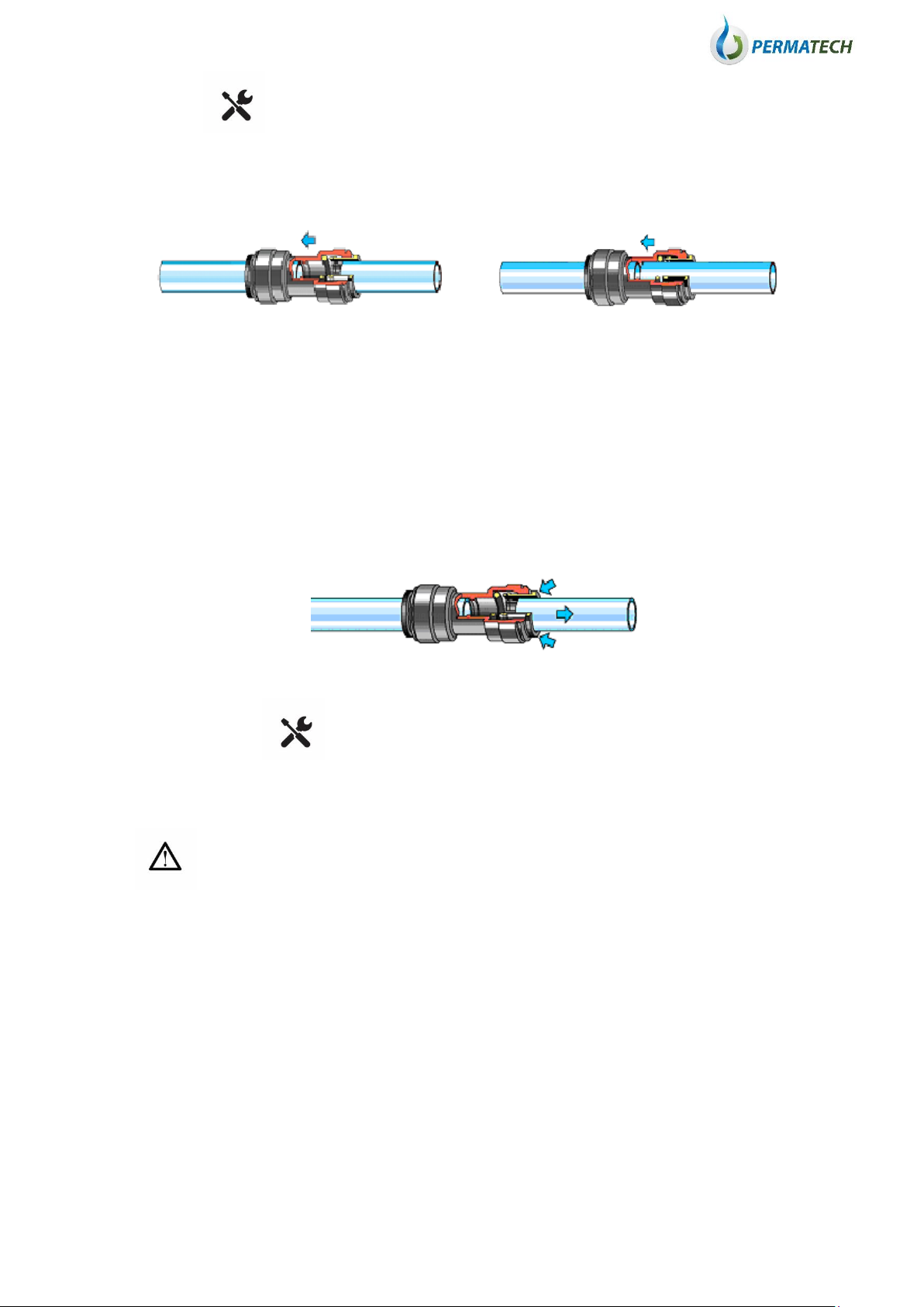
8. With all fittings in place, thread the Tube Fastening Nut and Collet, insert the tubing into the faucet inlet
and tighten the nut.
9. Connect the other free ends of the 1/4” tubing according to schemes on page 11.
7.3 STEP 3: PRESSURE TESTING AND PURGING
7.5
1. Check all tubing to be sure there are no kinked.
2. Turn the Storage Tank Valve to OFF position.
3. Turn RO faucet lever to continuous flow ON position (handle pointed up).
4. Turn the cold water supply main valve on slowly. When the system is pressurized, check for leaks.
5. You will hear the air purging from the system and within 5 minutes, the water should start dripping
from RO faucet. Once the water starts to drip, allow 20 more minutes for the water to flow through the
system and purge all the air trapped inside the system.
6. After 10 minutes, turn the Storage Tank Valve to the ON position (handel is parallel to the tubing).
7. Turn the RO faucet handle to the OFF position. Now the purified water will start going into the storage
tank.
CAUTION: You must purge the first two tanks of water from the system prior to consumption of the
product water. Do not drink the first 2 tanks of water produced by the system!
8. Allow the storage tank to fill for 2 hours. Then open the faucet untill the tank is empty and the flow just
drips from the faucet.
9. Close the faucet and allow the storage tank to fill again for 2 hours. Then open the RO faucet and empty
the tank again. After discharging the contents of the Storage Tank twice, you can start enjoying the pure
water.
NOTE: Check for leaks daily for the first week after installaion.

9
8. SYSTEM CARE AND MAINTENANCE
8.1 FILTER CARTRIDGES CHANGE
To change the prefilter cartridge, follow these instructions:
CAUTION: Any Replacement filters not recommended by the producer can cause severe
damage to the system and void all warranties.
1. Shut off the feed water supply to the system by turning the saddle valve or cold water faucet valve on the
water supply clockwise until it stops.
2. Press down on the faucet handle to release pressure and put faucet into OPEN position.
3. Allow few seconds for pressure in the system to drop.
4. Turn the cartridge counterclockwise to loosen it and remove the cartridge from the head (cap). Be careful
as the cartridges are filled with water.
5. Unpack new cartridges from protection foil and line up the new cartridge with the center of the head.
6. Turn the cartridge clockwise to tighten it.
CAUTION: Rinse the new cartridge for abuout 5 minutes before usage.
CAUTION: A higher frequency of filter changes may be necessary, dependenting on your feed water
quality. You should inspect the filters periodically and maintain a service record to establish a
maintenance schedule that is tailored to your water conditions.
Filter cartridges exchange: every 3 to 6 months.

10
9. TROUBLE SHOOTING
CAUTION: Regulary (eg. Once per month) check your TDS* level of feed water and purified water. Results
will keep you updated about the filtration efficiency and the filters condition.
*TDS (Total Dissolved Solids) – total content of substances dissolved in water measured in ppm (parts per milion
=mg/l)
Please check selected cases for general solution ideas:
PROBLEM
CAUSE
SOLUTION
Taste and/or smell
of chlorine in clean
water
Filter does not work – does not
remove chlorine from feed water.
Exchange the carbon filter and/or all filters.
Changed smell and
taste of clean water
Used filters.
Exchange the carbon filter and/or all filters.
Low system
capacity
Filters clogged with sediments.
Feed water does not comply with
the standard requirements.
Exchange sediment filters and/or all
filters. If the capacity does not
improve increase water pressure.

11
10. CONNECTION SCHEME
1. Sediment cartridge
2. Activated carbon cartridge
3. Ultrafiltration cartridge
Table of contents
Other Perma Tech Water Filtration System manuals
Popular Water Filtration System manuals by other brands

Danfoss
Danfoss IPS 8 user guide

Duraline Systems
Duraline Systems Vistacool NSVC-1 Installation guide & owner's manual

SMC Networks
SMC Networks SFE Series Operation manual

Filtration Group
Filtration Group AF 172 G2 Original instructions

Viking Pure
Viking Pure MiniMAXX VPM-MAXX user manual

HOMEPURE
HOMEPURE Water Filter user manual