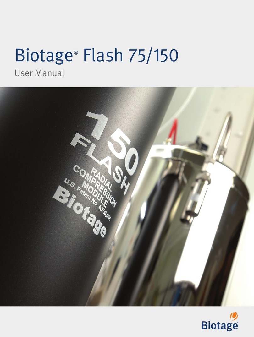
Biotage Flash 400 User manual

Biotage®Flash 400
User Manual

Biotage®Flash 400 User Manual | © Biotage 2018
Contents
Biotage®Flash
User Manual
CONTENTS
Introduction
1 Speed
1 Safety
1 Performance
Description and Specifications
2 Biotage®Flash 400 Frame
2 Radial Compression Module
4 Biotage®Flash 400 Prepacked Cartridge
4 Radial Compression Fluid Reservoir
5 Control Panel
6 Side Connection Panel
6 Hoist
7 Start-Up Kit
8 System Dimensions and Valves,
Gauges, and Regulators
10 Specifications
Safety
11 Intended Use
11 Working Volume
11 Education, Training, and Competence
11 Warranty and Liability
11 Service
11 Labels
12 Safety Requirements
Installation
14 Site Requirements
14 Ground the System
15 Gas Supply Connections
16 Solvent Inlets (A and B)
16 Fraction Outlets (1 and 2)
16 Drain Valve and Exhaust Ports
16 Tube Connections
Operation
17 Install a Cartridge
22 Fill the Radial Compression Fluid Reservoir
22 Pressurize the Radial Compression
Module and Fluid Reservoir
23 Test the Cartridge Sealing
24 Test a Biotage®Flash 400 Cartridge
25 Equilibrate the Cartridge
25 Load the Sample
25 Collect Fractions
26 Purge and Flush the Cartridge
27 Depressurize and Drain the System
28 Remove and Handle the Used Cartridge
29 Clean the System
30 Lock the Hoist in the Storage Position
Troubleshooting
31 Biotage®Flash 400 Radial Compression Module
31 Solvent Compatibly of O-Rings
32 Radial Compression Fluid Reservoir
32 Operation
General Information
33 Patents
33 Price List and Ordering Information
33 Download User Documentation
33 Manufacturer
33 Contact Us
Appendix
34 Warranty and Liability
34 Essential Tools List
34 Biotage®Flash 400 Spare Parts
35 Biotage®Flash 400 Process
and Instrumentation Drawing
Notes

Introduction
Introduction
Biotage®Flash 400 is a flash purification system based
on prepacked cartridge technology that provides users of
traditional self-packed glass columns with three critical
operational benefits: speed, safety, and performance.
Speed
Unlike glass columns, which operate at low pressure and
have very poor flow distribution, Biotage flash cartridges are
optimized for high speed separations. Purifications that might
otherwise require a full working day can be run in one hour.
For a chemist running just a single reaction and separation
per day, the annual gain in productivity can be as high as 15
additional weeks each year; time that could be used to develop
new compounds or processes. With the rising cost of labor,
the efficiencies afforded by this alone can exceed the cost of
the flash system and a year’s supply of cartridges.
Safety
Laboratory and process safety is a growing concern, with
many companies carefully reviewing current procedures and
techniques to reduce the risk of chemical exposure, injury, and
consequently their liability. Biotage Flash systems eliminate the
concerns of using glassware under pressure by utilizing durable
polyethylene cartridges that are prepacked and completely
self-contained, eliminating user exposure to silica dust, HP-API,
or any contaminants left after a separation.
Figure 1.Radial compression module overview.
The Flash 400 system is designed and manufactured to meet
the requirements of the EC machinery directive and the ATEX
product directive, and contains ASME/CE rated pressure
vessels. The design, fabrication, and pressure testing are
reviewed and confirmed by an independent inspector.
The hoist mechanism, including associated pneumatics, valves,
switches, and lifting hardware, should be regularly inspected in
accordance with local regulations and directives. Contact your
Biotage representative for additional information.
Performance
In addition to speed and safety, Biotage flash cartridges
improve both the performance and the reproducibility of
separations. The use of Biotage patented radial compression
technology (see Figure 1) reduces interstitial spaces (void
volume) within the packed bed. The optimized bed density
means that compounds are collected in narrow bands, which
results in higher separation efficiency. Unlike glass columns,
each Biotage flash cartridge will perform in the same way, time
after time.
Head assembly
Prepacked
cartridge
Compression
barrel
Flow distribution
plate
Frit
Media
Radial
pressure
applied
Cartridge
wall

Biotage®Flash 400 User Manual | © Biotage 2018
Description and Specifications
Description and Specifications
Figure 2
A
B
C
E
H
I
G
D
.Flash 400 system. A = hoist, B = hoist control box, C = cartridge
tool, D = prepacked cartridge, E = radial compression module, F = radial
compression fluid reservoir, G = control panel, H = solvent inlets and
fraction outlets, and I = air and nitrogen inlets.
Biotage®Flash Frame
The Flash 400 radial compression module is mounted on a
portable frame. The frame includes a side connection panel with
bulkhead compression fittings for connecting solvent reservoirs
(inlet A and B), collection vessels (outlet 1 and 2), a nitrogen
supply (radial compression fluid reservoir and module), and a
compressed air supply (solvent pump). The air supply for the
hoist is connected at the rear of the hoist. For more information
see “Installation” on page 14.
The system is fully plumbed and ready for installation.
Figure 14 on page 8 shows the overall dimensions.
Radial Compression Module
The Flash 400 radial compression module (see E in Figure 2)
is an ASME rated and CE marked pressure vessel. The barrel is
fabricated from 316L stainless steel while the top head, bottom
head, and clamps are machined from 316 stainless steel. The
interior and exterior surfaces have been mechanically polished.
The radial compression module is rated at 170 psig (11.7 bar)
maximum pressure. The system includes several pressure relief
valves to help ensure that the operating pressure does not
exceed this specification.
Note: The radial compression module’s polished surfaces must
be protected to minimize mechanical damage.
Additional Radial Compression Barrel
The system supports two interchangeable barrels for use with
either 400 mm x 300 mm (Flash 400M) or 400 mm x 600 mm
(Flash 400L) cartridges. One of the radial compression barrel
sizes is included in the system and the barrel of the other size
can be ordered.
O-Rings
The head assembly includes a two piece stainless steel
cartridge seal adapter with two Chemraz O-rings (A & B); see
5 and 6 in Figure 3. The cartridge seal adapter seals against
the seal adapter plate when the face O-ring (A) is compressed.
The radial O-ring (B) seals the adapter to the head.
The top and bottom head assemblies seal to a tapered surface
on the cartridge and to the radial compression barrel with either
Viton (as shipped) or EPDM (spares) O-rings (C & D); see 3 and 2
in Figure 3. These O-rings are non-product contact surfaces.
The Viton and EPDM O-rings are very compressible and will
seal reliably up to 100 psig (6.9 bar). EPDM is resistant to polar
solvents but will swell in many common aliphatic and aromatic
solvents. Viton is resistant to non-polar solvents, but will
swell in the typical polar modifiers. For solvent compatibility
information, see Table 1.
Table 1 only covers a limited number of commonly used
solvents. To check the compatibility of a particular solvent or
solvent mixture, soak an O-ring in the solvent/mixture for one
hour and then inspect it for swelling. If the O-ring swells in use,
allow it to dry out in a fume hood until it returns to its normal
size (typically overnight).
Inspect your O-rings before each run and replace any O-ring
that shows signs of wear or damage or that leaks at your typical
operating pressures. See Table 2 for part numbers and Figure 3
for location.
F

Description and Specifications
O-Ring Material Composition
Type Solvent
Polarity
Solvent Viton EPDM
(Ethylene
Propylene)
Chemraz
Normal
Phase
0.1 Hexane Good Poor Good
2.4 Toluene Fair Poor Good
2.5 MTBE Poor Poor Good
3.1 DCM Fair Fair Good
3.9 IPA Good Good Good
4.0 THF Poor Poor Good
4.4 Ethyl Acetate Poor Good Good
5.1 Methanol Poor Good Good
Reversed
Phase
5.8 Acetonitrile Poor Good Good
6.4 DMF Poor Fair Good
…Acids Poor Good Good
…Bases Poor Good Good
10.0 Water Good Good Good
Table 1.General solvent compatibility chart.
Figure 3
7
89
1
6
5
4 2
3
89
10
11
.Cut-away view of the top head assembly (left) and expanded view of the cartridge seal adapter (right).
1 = top head clamp, 2 = O-ring “D” size 387, Viton (as shipped) or EPDM (spares), 3 = O-ring “C” size 460, Viton (as shipped) or EPDM (spares),
4 = cartridge, 5 = O-ring “A” size 222, Chemraz, 6 = O-ring “B” size 223, Chemraz, 7 = top head assembly, 8 = cartridge seal adapter (adjustable),
9 = seal adapter housing (fixed), 10 = flow distribution plate (inside the cartridge), and 11 = frit.
Flash 400
Compression Module
Part
Number
No.
Above
Material Product
Contact
Size
Ref
Imp: CD, ID, OD
(Inches)
Std. Qty.
Installed
Spares In
Start-Up Kit
Barrel O-Rings (D) 03020 2 Viton No #387 2 2
Barrel O-Rings (D) 03019 2EPDM No #387 0 4
Barrel O-Rings (D) 03020-K 2Kalrez No #387 0 0
Top/Bottom Head (C) 02939 3 Viton No #460 1/4, 15½, 16 2 0
Top/Bottom Head (C) 03011 3EPDM No #460 1/4, 15½, 16 0 0
Top/Bottom Head (C) 08648 3 Chemraz No #460 1/4, 15½, 16 0 2
Top/Bottom Head (C) 02939-K 3Kalrez No #460 1/4, 15½, 16 0 0
Cart Seal Adapter (A) 06875 5 Chemraz Yes #222 1/8, 1½, 1¾ 2 2
Cart Seal Adapter (B) 03010 6 Chemraz No #223 2 2
Table 2.Radial compression module O-rings.

Biotage®Flash 400 User Manual | © Biotage 2018
Description and Specifications
Top Head Assembly Valves
The top head assembly has the following valves.
Valve Description
MV-02 Three-way injection valve. Selects the solvent or
sample inlet (see Figure 4). During cartridge removal,
compressed gas may be blown through this valve and
through the cartridge to remove solvent.
MV-03 Cartridge compression vent valve. Open the valve to
purge air from the radial compression chamber when
compressing the cartridge (see Figure 5).
MV-04 Vacuum break valve, top. Open the valve to break any
vacuum that develops when the cartridge is in use (see
Figure 5). Used when preparing to remove a cartridge
or testing if the cartridge seal adapter’s O-ring has
sealed properly.
Figure 4.The three-way injection valve (MV-02) with the handle pointing
toward the solvent inlet tube.
Figure 5.The cartridge compression vent valve (MV-03) and the top
vacuum break valve (MV-04) closed (left image) and opened (right image).
Biotage®Flash Prepacked Cartridge
The system supports two interchangeable barrels for use with
either 400 mm x 300 mm (Flash 400M) or 400 mm x 600 mm
(Flash 400L) cartridges, with the capacity to purify up to 8 kg*
of crude reaction mixture. One of the radial compression barrel
sizes is included in the system and the barrel of the other size
can be ordered.
A variety of pre-packed cartridges are available depending on
the purification goal and cartridges can be custom packed
with
the preferred chromatography media for your process. The media
in each cartridge is self-contained, improving
handling and
eliminating exposure to contamination and impurities or
HP-APIs (high potency active pharmaceutical ingredients).
The cartridges are shipped in a sealed polyethylene shipping
bag to minimize water vapor adsorption. Each cartridge includes
certificates of compliance and conformance with detailed
information for your records in GLP or cGMP environments.
Note: Biotage cartridges are optimized for single use.
All warranties are void if the cartridges are used multiple times.
Specification Flash 400M Flash 400L
Size D x H 400 x 300 mm 400 x 600 mm
Mass of Biotage®KP-Sil Silica 20 kg 40 kg
Column Volume 28 liters 56 liters
Sample Size 4 kg* 8 kg*
Flow Rate 1-6 L/min 1-6 L/min
Table 3.Flash cartridge specifications.
* The amount of sample that can be purified will depend on the stationary
phase and ease of separation. Our new advanced spherical silicas with
greater surface area routinely support purification using approximately
double the traditional silica sample loadings.
Radial Compression Fluid Reservoir
Biotage provides an electropolished 304 stainless-steel
fluid reservoir with the capacity of 12 liters (see F in Figure 2).
The oval lid has a clamp that screws shut and a solvent proof,
PTFE-encapsulated Viton O-ring to seal the lid in place.
The fluid reservoir is fitted with a pressure gauge (PG-03) and a
safety relief valve (PSV-03) that activates at pressures in excess
of 125 psi (8.6 bar).
Note: Biotage recommends using the same solvent for both the
eluent and the radial compression fluid.
Figure 6.The pressure gauge on the radial compression fluid reservoir.

Description and Specifications
Control Panel
The system includes a control panel with the following pressure
gauges and valves required to operate the system.
Label Description
PG-01 Pump pressure gauge. Monitors the solvent pump (P-01)
outlet pressure.
PG-02 Cartridge compression pressure gauge. Monitors the
pressure inside the radial compression module.
MV-01 Solvent select valve. Selects which of the two solvent
inlets (Aor B) that will be used.
MV-06 Fraction select valve. Selects which of the two outlets
(1or 2) the elution stream will exit through.
MV-07 Cartridge compression valve.
Opens the line between the radial compression
chamber and the radial compression fluid reservoir,
which compresses the cartridge if the fluid reservoir is
pressurized. PG-02 and PG-03 readings will equalize.
Closes the valve.
MV-08 Solvent pump valve. Turns the solvent pump on or off
(Oor I) by opening or closing the line between the air
supply and the pump.
MV-09 Reservoir pressure valve.
Pressurizes the radial compression fluid reservoir
by connecting it to the nitrogen supply.
Used when checking that the pressure in the radial
compression fluid reservoir can be maintained.
Vents the radial compression fluid reservoir by
opening it to the atmosphere. The exhaust port is
located on the side connection panel.
MV-11 Pump flow rate control. Regulates the compressed air
pressure to the solvent pump (P-01). Turn the knob
counterclockwise to increase the solvent flow rate and
clockwise to decrease it.
Table 4.The control panel.
Safety Positions
Before introducing compressed air or nitrogen into the system,
ensure that the following valves on the control panel are in their
safety position as listed in Table 5 below.
Valve Safety Position
MV-11 Clockwise until stopped
MV-08 O(closed)
MV-09 (vent)
MV-07 (open/compress)
Table 5.Valve safety positions.
Figure 7
MV-05
MV-10
1 2
2
MV-06
MV-09
MV-08
PG-01
MV-07
MV-01
A1
PG-02
BIOTAGE®FLASH 400
A B
B
MV-11
.The control panel.
Pump Valve Handle with Safety Latch
The pump valve handle has an automatic safety latch feature
to prevent accidental movement of the handle from one setting
to another.
To operate this valve, the safety latch must be pressed in and
held while the handle is moved. Upon release, the handle
becomes latched in its current position.
To secure the handle in a specific position and prevent anyone
from changing the setting, the latch mechanism includes an
opening for installing a padlock or other locking device (see
Figure 8).
Figure 8.Pump valve handle with safety latch.

Biotage®Flash 400 User Manual | © Biotage 2018
Description and Specifications
Hoist
The hoist (see A in Figure 2 on page 2) is used to move
and seal the top head assembly, insert and remove cartridges,
and when necessary, move the radial compression barrel.
The maximum working load is 125 kg (275 lbs).
The hoist is pneumatically operated and has a separate,
dedicated compressed air input connection with a maximum inlet
pressure of 100 psig (6.9 bar). The air pressure to the hoist motor
is set internally at the factory to approximately 30 psig (2.1 bar).
For safety reasons, this internal setting must not be changed.
When not in use, the hoist must be locked in the “storage”
position. See the instructions on page 30.
Figure 10.Hoist control box.
Cartridge Tool
The cartridge tool (see Figure 11) is used to insert and remove
cartridges with the hoist.
Grasp the eyebolt at the top of the cartridge tool with both
hands and lift the tool onto the top of the cartridge. Center the
cartridge tool on the top of the cartridge and hand turn the
knurled knob (below the eyebolt) clockwise until it will not turn
any more. This opens the four plates in the tool and forces them
to lock securely into the cartridge lifting groove.
Figure 11
A
B
C
D
.The cartridge tool. A = eyebolt, B= locking nut, C = knurled
knob, and D = moveable plate (4).
If the knurled knob tightens without the plates fully extending,
spread the plates by hand and push the spreader shaft down
until it is in the grooves of the plates. Ensure that the cartridge
tool outer ridge is fully engaged into the mating cartridge lifting
groove. Re-tighten the knurled knob.
Side Connection Panel
The side connection panel has the following ports and valves.
Label Description
Solvent inlets Aand B.
Fraction outlets 1and 2.
MV-10 Radial compression drain valve.
Closes the valve.
Drains the fluid from the radial compression
chamber. Used before removing the cartridge.
MV-05 Vacuum break valve, bottom.
Closes the valve.
Breaks any vacuum that develops when the
cartridge is in use. Used when preparing to remove
a cartridge or when testing if the cartridge seal
adapter’s O-ring has sealed properly.
Compressed air inlet for the solvent pump.
Nitrogen inlet. Used to pressurize the radial compression
fluid reservoir and the radial compression module.
Exhaust port for when venting the radial compression fluid
reservoir using the MV-09 valve.
Safety relief port for the radial compression module. The
module is rated at 170 psig (11.7 bar) maximum pressure.
Table 6.The side connection panel.
Figure 9
MV-05
MV-10
1 2
2
MV-06
MV-09
MV-08
PG-01
MV-07
MV-01
A1
PG-02
BIOTAGE®FLASH 400
A B
B
MV-11
.The side connection panel.

Description and Specifications
Ensure that the cartridge tool cannot be moved within the
cartridge top. If the tool can be moved, loosen the knurled knob
and repeat the tightening process to re-engage.
Move the hoist arm so that the safety hook is centered over the
cartridge tool and then fasten the hook to the tool’s eyebolt.
Head Sling Assembly
The head sling assembly (see Figure 12) is used to move and
seal the top head assembly with the hoist. It can also be used to
move the radial compression barrel to get access to the bottom
head assembly or to change the barrel (see “Additional Radial
Compression Barrel” on page 2).
To move the top head assembly, attach the pivot arms on the
head sling assembly to the eyebolts on the top head assembly
using the quick-release pins. Turn the pivot arms so that the end
attached to the sling cable faces inward, toward the center of
the head assembly, as shown in Figure 25 on page 18.
To seal the head assembly, attach the pivot arms on the head
sling assembly to the fulcrum arms using the quick-release pins.
Turn the pivot arms so that the end attached to the sling cable
faces outward as shown in Figure 12.
To lift the radial compression barrel, attach the pivot arms to
the fulcrum arms using the quick-release pins. Turn the pivot
arms so that the end attached to the sling cable faces inward,
toward the center of the barrel.
Attach the top ring of the head sling assembly to the hoist safety
hook. Ensure that the top ring is attached to the hook with the
narrow end up and the closure nut fully threaded and tightened.
Figure 12
A
B
C
D
F
E
.Sealing the head assembly. A = hoist safety hook, B = top ring,
C = sling cable, D =pivot arm (3), E = fulcrum arm (3), and F = quick-
release pin (3).
Start-Up Kit
Biotage provides a start-up kit consisting of the following items:
Description QTY UOM P/N
Cartridge tool 1Ea. 03468
Head sling assembly 1Ea. 08327
Wedge tool (see Figure 13) 1Ea. 05557
Barrel O-rings, size 387, Viton 2Ea. 03020
Barrel O-rings, size 387, ethylene
porpylene
4Ea. 03019
Top and bottom head assembly O-rings,
size 460, chemraz 505
2Ea. 08648
Cartridge seal adapter O-rings, size 222
chemraz
2Ea. 06875
Cartridge seal adapter O-rings, size 223
chemraz
2Ea. 03010
Tubing assembly 1.2" FLEX 4Ea. 07087
Tubing, 1/4" OD yellow LDPE 20 Ft. 01354
Tubing, 1/4" OD blue LDPE 20 Ft. 01487
Connector, male 1/4" tube x 1/4" MNPT 1Ea. 02184
Nut, hex 3/8"-16 UNC 18-8 SST 2Ea. 03286
Washer, flat 3/8" 18-8 SST 2Ea. 03287
Muffler, 3/8" 40µ POREX 1Ea. 01801
Quick guide 1Ea. 416118
User manual (this publication) 1Ea. 04149
For more information on the O-rings, see “O-Rings” on page 2.
Figure 13.The wedge tool.

Biotage®Flash 400 User Manual | © Biotage 2018
Description and Specifications
System Dimensions and Valves,
Gauges, and Regulators
All valves used on the Flash 400 system are fabricated from 316
stainless steel with a PTFE seat and rated by the manufacturer
to at least 200% of the maximum system working pressure.
The pressure gauges operate in contact with the radial
compression fluid. They are rated to at least 150% of the
Figure 14.Component location and system dimensions.
maximum working pressure and are graduated as appropriate
for convenient operation. The bodies are stainless steel with
glass lenses.
For details about each component, see Figure 14 below,
Table 7 on page 9, and the Flash 400 flow diagram located
on page 35. For information on the ports on the side
connection panel, see Table 6 on page 6.

Description and Specifications
Item Description
MV-01 Solvent select valve. Selects which of the two solvent
inlets (Aor B) that will be used.
MV-02 Three-way injection valve. Selects the solvent or sample
inlet (see Figure 4 on page 4). During cartridge
removal, compressed gas may be blown through this
valve and through the cartridge to remove solvent.
MV-03 Cartridge compression vent valve. Open the valve to
purge air from the radial compression chamber when
compressing the cartridge (see Figure 5 on page 4).
MV-04 Vacuum break valve, top. Open the valve to break any
vacuum that develops when the cartridge is in use
(see Figure 5 on page 4). Used when preparing
to remove a cartridge or testing if the cartridge seal
adapter’s O-ring has sealed properly.
MV-05 Vacuum break valve, bottom.
Closes the valve.
Breaks any vacuum that develops when the
cartridge is in use. Used when preparing to
remove a cartridge or when testing if the cartridge
seal adapter’s O-ring has sealed properly.
MV-06 Fraction select valve. Selects which of the two outlets
(1or 2) the elution stream will exit through.
MV-07 Cartridge compression valve.
Opens the line between the radial compression
chamber and the radial compression fluid
reservoir, which compresses the cartridge if the
fluid reservoir is pressurized. PG-02 and PG-03
readings will equalize.
Closes the valve.
MV-08 Solvent pump valve. Turns the solvent pump on or off
(Oor I) by opening or closing the line between the air
supply and the pump.
MV-09 Reservoir pressure valve.
Pressurizes the radial compression fluid reservoir
by connecting it to the nitrogen supply.
Used when checking that the pressure in the radial
compression fluid reservoir can be maintained.
Vents the radial compression fluid reservoir by
opening it to the atmosphere. The exhaust port is
located on the side connection panel.
MV-10 Radial compression drain valve.
Closes the valve.
Drains the fluid from the radial compression
chamber. Used before removing the cartridge.
MV-11 Pump flow rate control. Regulates the compressed
air pressure to the solvent pump. Turn the knob
counterclockwise to increase the solvent flow rate and
clockwise to decrease it.
Item Description
P-01 Pneumatic solvent pump. Moves solvent through
the system.
PG-01 Pump pressure gauge. Monitors the solvent pump
outlet pressure.
PG-02 Cartridge compression pressure gauge. Monitors the
pressure inside the radial compression module.
PG-03 Reservoir pressure gauge. Monitors the radial
compression fluid reservoir pressure.
PRR-01 Air pressure regulator (with filter and gauge). Regulates
the incoming compressed air pressure for the solvent
pump. Set to a maximum of 100 psig (6.9 bar).
PRR-02 Hoist air inlet. Compressed air supply inlet for the hoist,
max 100 psig (6.9 bar). Air pressure to the hoist motor
is set internally at the factory to approximately 30 psig
(2.1 bar). This internal setting must not be changed.
PSV-01 Safety relief valve, solvent pump. Relieves the radial
compression chamber if the pressure reaches 170 psig
(11.7 bar). ASME rated.
PSV-02 Safety relief valve, chamber. Relieves the radial
compression chamber if the pressure reaches 170 psig
(11.7 bar). ASME rated.
PSV-03 Safety relief valve, fluid reservoir. Monitors the radial
compression fluid reservoir pressure. When the
cartridge compression valve (MV-07) on the control
panel is set to on/compress, the reading on this gauge
(PG-03) will be equal to the reading on the cartridge
compression pressure gauge (PG-02).
Table 7.Flash 400 valves, gauges, and regulators.

Biotage®Flash 400 User Manual | © Biotage 2018
Description and Specifications
Specifications
Item Rating
Hoist load rating Working load rating is 125 kg (275 lbs)
Nitrogen inlet 100 psig (6.9 bar) maximum
Compressed air inlet
(solvent pump) 100 psig (6.9 bar) maximum
Compressed air inlet
(hoist) 100 psig (6.9 bar) maximum
Compressed gas supply
tubing
200 psig (13.8 bar) minimum working
rating
System weight Up to 650 kg (1433 lbs) typical
Installation floor load
requirement 732 kg/m2 (150 lbs/f t2) minimum
Head assembly weight 68 kg (149 lbs) each head
Head clamp weight 11.3 kg (25 lbs) each half
Radial compression
pressure 80 to 100 psig (5.5 to 6.9 bar)
Solvent pressure Set to at least 20 psig (1.4 bar) less than
radial compression pressure, 80 psig
(5.5 bar) maximum
Table 8.Specifications.
Chemical Resistance
The following chemicals can be used in the wetted parts of
the system:
»
Acetone
»
Dichloromethane (methylene chloride, DCM)
»
Toluene
»
Acetonitrile (MeCN)
»
Tetrahydrofuran (THF)
»
Triethylamine (TEA)
»
N,N-dimethylformamide (DMF)
»
Ethyl acetate (ethyl ethanoate, EtOAc)
»
N-methyl-2-pyrrolidone (NMP)
»
Dimethylsulfoxide (DMSO)
»
Ethanol (EtOH)
»
Methanol (MeOH)
»
2-propanol (isopropanol, IPA)
»
Formic acid (methanoic acid, HCOOH)
»
Acetic acid (Ethanoic acid, HOAc, AcOH)
»
Deionized water (H2O)
»
Trifluoroacetic acid (TFA), max 5 % (by volume)
»
n-Heptane
»
Piperidine (pip)
»
Pyridine (pyr)
»
Ammonia (NH3) conc.23-27 % (by weight)
»
tert-Butyl methyl ether (TBME)
»
Diethyl ether
»
10 mM phosphate buffered saline, pH= 7.4
»
50 mM phosphate-citrate buffer, pH= 5.0
»
Boric acid/NaOH/KCl buffer, pH=11
Note: Always check the O-rings’ compatibility with the solvent
or solvent mixture that you want to use. For more information,
see “O-Rings” on page 2.

Safety
Intended Use
Biotage Flash 400 system is intended solely for purification.
The system must be operated in a controlled environment with
an ambient temperature between 4°C and 32°C (39°F and 90°F)
by trained professionals. The system must not be installed or
used near a potential ignition source. It is the responsibility of
the customer to classify (zone) their particular environment in
order to verify that it meets the requirements of the directive
1999/92/EC. All operations must be performed:
»
According to the user documentation
delivered with the system.
»
According to instructions available at www.biotage.com.
»
According to instructions given by the
technical support staff from Biotage.
»
Within limits set by the system’s technical specification and
in line with user standard operating procedures (SOPs).
Failure to follow those instructions and operate within the limits
set by the technical specification may result in personal injury
and/or equipment damage.
Working Volume
The data plate on the radial compression module states a
working volume as required by the Pressure Equipment Directive
(PED) 2014/68/EU. In line with regulations, this is the available
volume after the cartridge and allowable permanent parts have
been excluded from the total theoretical volume. The volume is
therefore not the volume of a cartridge, or a purification metric
such as “column volume”. For further information on scale-up,
please contact your local Biotage representative.
Education, Training, and Competence
It is your responsibility to provide all applicable health and
safety regulations to your personnel. You must also ensure that
all personnel involved in the operation and maintenance of the
system fulfill the following criteria:
»
Have the necessary education, training, and competence
required for the intended use of the system.
»
Observe general and specific safety regulations for the
use of the system and its accessories at all times in order
to reduce the risk of personal injury, fire, and explosion.
Warranty and Liability
See the “Biotage Terms & Conditions of Sale” document at
www.biotage.com.
Service
All service must be performed by an authorized Biotage service
engineer. Before handing over the system for service, it should
be emptied of all liquid and cleaned from harmful residues.
It is the responsibility of the customer to inform Biotage®
1-Point Support™representatives if the system has been used
with hazardous biological, radioactive, or toxic samples and/
or solvents, prior to any service being performed. If returning
equipment to Biotage, this should be done in accordance with
the material return procedures supplied separately by Biotage.
Only genuine Biotage spare parts must be used in the system.
Labels
Labels used on the system:
In accordance with all the essential requirements of
all applicable European product directives; see the
Declaration of Conformity.
In accordance with the ATEX Product Directive,
2014/34/EU for Group II, Category 2G equipment.
The equipment is intended for use in areas in which
explosive atmospheres caused by gases, vapors, or
mists or air/dust mixtures are likely to occur.
Manufacturer.
Consult accompanying user documentation.
Note: The system is ASME rated and in accordance with both
U.S. and Canadian safety standards; see the Declaration of
Conformity.
Safety

Biotage®Flash 400 User Manual | © Biotage 2018
Safety
Safety Requirements
You must observe all safety requirements when installing and
operating the system. Failure to install or use the system in
a manner specified by Biotage may result in personal injury
and/or equipment damage.
If the system has been damaged or does not function properly,
turn off the gas supplies, depressurize the system (all pressure
gauges should read zero (0) bar/psig), open the vacuum break
valves (see MV-04 and MV-05 in Figure 14 on page 8), and
contact Biotage 1-Point Support (www.biotage.com).
Installation
»
The system must be unpacked and installed by an
authorized Biotage service engineer. Prepare the
installation site as described on page 14.
»
Follow regional safety practices when handling
and moving shipping boxes and containers,
and when moving the system.
»
The total weight of the package including the system is up to
1043 kg (2300 lbs) depending on the system configuration.
Use suitable lifting equipment when moving the package.
»
The system can weigh up to 650 kg (1433 lbs). It must
be installed on a level floor that can support the
system weight concentrated on the four wheels.
»
The system must be placed in a well-ventilated walk-in
fume hood or an equivalent enclosure that is capable
of exhausting 0.6 m3/min (21.2 ft3/min). Follow
local and national safety regulations for installing a
system inside a fume hood and the safety regulations
supplied by the fume hood manufacturer.
»
Never install or use the system near
a potential ignition source.
»
The system, when operated with non-polar solvents
such as hexane, methylene chloride, etc., can build up a
high static electricity charge, which in certain conditions
can be dangerous. To eliminate any risk of a static
discharge, the system and ancillary containers must
be grounded before use as described on page 14.
Failure to follow these grounding instructions may result
in equipment damage, personal injury, or death.
»
A trained person must verify that the system and
ancillary containers are grounded before each run.
Nominal resistance must be below 5 Ohm between
ground and each metal point in the system.
»
Only nitrogen must be used to move radial
compression fluid through its flow path due to the
risk of exothermal reaction and/or explosion.
»
Ensure that the inert gas tubing connected to the
system cannot come in contact with chemicals.
Corrosives and solvents can dissolve the tubing.
»
The outlets of the three safety relief valves (located on
the radial compression module, the air pressure regulator
to the solvent pump, and the radial compression fluid
reservoir) must be directed away from the operator.
»
To avoid injury to yourself or damage to the system,
never apply gas pressures greater than 100 psig
(6.9 bar) to the system inlet gas ports.
»
Do not over-tighten the fittings or the
tubing may become damaged.
»
Never modify the system components in any way
and always use spare parts supplied by Biotage.
Failure to follow this warning may result in serious
personal injury or death. Please contact your Biotage
representative for questions regarding this.
Operation
»
Use the system only for its intended purpose, as described
in the user documentation delivered with the system and
user documentation available at www.biotage.com. If the
system is used in a manner not specified by Biotage, the
safety features of the system may be compromised.
»
The system must not be operated unattended.
»
Never operate the system if damaged.
»
Only nitrogen must be used to move radial
compression fluid through its flow path due to the
risk of exothermal reaction and/or explosion.
»
Inspect the head clamps before and after each use.
If the clamp, threaded studs, nuts, or washers show
any sign of wear or damage, replace it/them. Only use
clamps, studs, nuts, and washers supplied by Biotage.
»
Confirm that the head clamps are tight before compressing
the radial compression module. Hand-tighten the clamps,
to a torque of 34 Nm (25 ft-lb). Ensure that the space
between the clamp halves is distributed evenly on both
sides. The gap should be approximately 10 mm (0.4")
on both sides. If the cartridge is not sealed properly,
replace the O-rings (see Figure 3 on page 3)
and retry, or contact Biotage 1-Point Support.
»
Ensure that all clamps are properly closed before
introducing pressure into the system.
»
Before removing the head assembly, ensure that
the system is depressurized (all pressure gauges
should read zero (0) bar/psig) and completely
drained, and the vacuum break valves (see MV-04
and MV-05 in Figure 14 on page 8) are open.
»
Ensure that the pump pressure gauge on the control
panel (see PG-01 in Figure 14 on page 8) reads
zero (0) bar/psig before disconnecting the stainless
steel overbraided solvent inlet tube from the three-way
injection valve, or the three-way injection valve.
»
Never remove a tube or system component
when it is under pressure.

Safety
»
The clamp halves must be held to prevent them from falling
when striking them with the wedge tool or a plastic-faced
mallet. Each half weighs approximately 11.3 kg (25 lbs).
»
When closing the radial compression fluid reservoir lid,
ensure that it is seated properly to ensure a secure seal.
»
Only use unmodified Biotage cartridges.
»
Never attempt to run the system without a
cartridge, or with the wrong size of cartridge.
»
Always equilibrate the cartridge.
»
Equilibrate the cartridge at a low flow rate
to avoid extreme temperature rise.
»
Only use waste containers and fraction collection
vessels that are grounded or made of glass.
»
A fume extractor must be used for open waste
containers and fraction collection vessels.
»
Do not place solvent reservoirs on top of any part of
the system. Any spillage can seriously damage the
equipment, resulting in potential safety hazards.
»
The system contains various exhaust ports. If the solvent
in use should not be released as a liquid or vapor into
the general atmosphere, contact Biotage for instructions
on how to safely vent these vapors and liquids.
»
To prevent spray hazards, the cartridge compression vent
port on the top head assembly (see MV-03 in Figure 14
on page 8) and the safety relief port for the radial
compression module on the side connection panel (see
Table 6 on page 6) must have the supplied frits
or appropriate tubing installed during operation.
»
Disposing of the used cartridge and media as a unit
reduces the exposure of plant personnel to the residual
solvent and any potentially hazardous by-products.
Biotage recommends prompt disposal of used cartridges.
»
The cartridge shipping containers are not considered
leak proof. The containers are resistant to most solvents
for 100 days when stored at 37.8°C (100°F) or less.
Some solvents may dissolve the plastic shipping bag.
»
Follow all applicable safety procedures
when working with bottled gas.
»
Follow all generally-accepted lab safety procedures
and applicable laws and regulations.
»
Always follow local and national safety
regulations related to storage, handling and
disposal of chemicals, samples and waste.
»
Read and understand the safety data sheet (SDS)
provided by the chemical manufacturer before
storing, handling, working with, or disposing
of any chemical or hazardous substance.
»
In many cases the system will be used in a Class I,
Division I, Group C/D hazardous area (equivalent to
EEx D IIc T4) as defined by the ANSI/NFPA 70, American
National Standards for Electrical Installations. Many
solvents are both flammable and toxic and must be
handled by trained operators who follow government
and corporate safety regulations and guidelines.
»
Personnel working with or near the system must
wear applicable safety clothing and gear (such as
solvent-resistant clothing and gloves, steel toe
shoes, and hearing, face, and eye protection) that
comply with local and national safety regulations.
Hoist
»
The hoist motor internal air pressure setting must
not be changed from the factory-set value.
»
When operating the hoist, do not attempt to lift loads
greater than 125 kg (275 lbs), and always wear steel
toe safety shoes, and hearing and eye protection.
»
Visually inspect the hoist, cartridge tool, and head
sling assembly before each use to ensure that no
parts are damaged or loose. If any problems are
found, solve them before using the equipment.
»
Confirm that the four plates of the cartridge
tool are fully extended and engaged with the
cartridge lifting groove, the knurled knob is fully
tightened (clockwise), and the locking nut is in
place before attempting to raise the cartridge.
»
Ensure that the top ring on the head sling assembly is
attached to the hoist with the narrow end up and the
closure nut fully threaded and tightened, and that the
cables are not twisted and are clear of obstacles.
»
To avoid cable damage, do not raise the cable so
high that the cable safety wrap (above the hoist
hook eyelet) is drawn into the hoist pulley.
»
Use caution when moving the head assembly
while attached to the hoist; the weight of the head
assembly (68 kg; 149 lbs) can cause it to swing
excessively if the hoist is rotated at a high speed.
»
Do not perform any maintenance tasks on the hoist unless
it is completely disconnected from the inlet air supply.

Biotage®Flash 400 User Manual | © Biotage 2018
Installation
Warning
»
The system must be unpacked and installed by an authorized
Biotage service engineer.
»
Follow regional safety practices when handling and moving
shipping boxes and containers, and when moving the system.
»
The total weight of the package including the system is up to
1043 kg (2300 lbs) depending on the system configuration.
Use suitable lifting equipment when moving the package.
»
Observe general and specific safety regulations for the use of
the system and its accessories at all times in order to reduce
the risk of personal injury, fire, and explosion; see the “Safety”
chapter on page 11.
Site Requirements
Before the system is installed, the installation site should be
prepared as follows:
Fume Hood/
Ventilation
System
The system must be placed in a well-ventilated
walk-in fume hood or an equivalent enclosure
that is appropriate for safe handling and
exhausting large quantities of sample, solvent, and
fractions and capable of exhausting 0.6 m3/min
(21.2 ft3/min). Follow local and national safety
regulations for installing a system inside a fume
hood and the safety regulations supplied by the
fume hood manufacturer.
A fume extractor must be used for open waste
containers and fraction collection vessels.
Never install or use the system near a potential
ignition source.
Floor Load
Capacity
The system can weigh up to 650 kg (1433 lbs).
It should be installed on a level floor that has a
minimum floor load rating of 732 kg/m2(150 lb/f t2).
The system is stable under normal usage.
Note: If the system will be moved from one area
to another, carefully evaluate the floor condition
between each point to ensure that the load ratings
are adequate.
Dimensions Review Figure 14 on page 8 to determine the
space allowances needed to set up and operate
the system. Consider the following clearance
recommendations:
»
A minimum of 25 cm (10") clearance on the
sides of each unit for solvent/air connections.
»
A minimum height clearance of 250 cm
(100") for the hoist to reach full extension.
»
Enough space behind the system
to allow operator access.
»
A minimum clear radius of approximately 60 cm
(24") is required in front of the system to
provide clearance for the range of motion of the
hoist when inserting and removing cartridges.
Operating
Temperature
4°C to 32°C (39°F to 90°F)
Nitrogen
Supply
100 psig (6.9 bar), dry and clean.
Compressed
Air Supply
100 psig (6.9 bar), clean and dry; however, slightly
lubricated is allowable.
Note: If lubricated air is used, appropriate
safety precautions must be taken to prevent the
lubricant in the air exhaust from contaminating the
surrounding area.
Ground the System
Warning
»
The system, when operated with non-polar solvents such as
hexane, methylene chloride, etc., can build up a high static
electricity charge, which in certain conditions can be dangerous.
To eliminate any risk of a static discharge, the system and
ancillary containers must be grounded before use as described
below. Failure to follow these grounding instructions may result
in equipment damage, personal injury, or death.
»
A trained person must verify that the system and ancillary
containers are grounded before each run. Nominal resistance
must be below 5 Ohm between ground and each metal point in
the system.
Whenever organic solvents flow from one point to another there
is the possibility of dangerous static electric buildup along the
path. To eliminate any risk of a static discharge, the systems
and ancillary containers must be grounded before use.
To ground the system, connect a ground wire between the
3/8"-16 UNC threaded ground stud on the system (see Figure 15)
and a grounding point, such as a metal cold water pipe.
Figure 15.Electrical ground stud location.
Installation

Installation
Note: To be an acceptable grounding point, the entire run of
pipe must be made of metal. Have a qualified person, such as
an electrician, verify that the point is grounded before operating
the system.
Verify that the system and ancillary containers are grounded using
an electrical multimeter (DVM). Nominal resistance must be below
5 Ohm between ground and each metal point in the system.
Gas Supply Connections
Warning
»
To avoid injury to yourself or damage to the system, never apply
gas pressures greater than 100 psig (6.9 bar) to the system inlet
gas ports.
»
Only nitrogen must be used to move radial compression fluid
through its flow path due to the risk of exothermal reaction
and/or explosion.
»
Ensure that the inert gas tubing connected to the system cannot
come in contact with chemicals. Corrosives and solvents can
dissolve the tubing.
»
Do not perform any maintenance tasks on the hoist unless it is
completely disconnected from the inlet air supply.
Recommended Tubing
Biotage recommends stainless steel or brass tubing or
stainless steel overbraided PTFE tubing for the gas supply
lines. The tubing must be rated to at least 200 psig (13.8 bar)
at the maximum working temperature. The gas tubing must be
protected from abrasion, kinking, or mechanical damage.
Before connecting gas tubing to the system:
1. Blow the gas tubing clean with clean, dry gas.
2. Ensure that the pump valve (MV-08) and the reservoir
pressure valve (MV-09) on the control panel are in the
following positions:
Valve Position
MV-08 O(closed)
MV-09 (vent)
3. Ensure that the air pressure regulator (see PRR-01 in
Figure 14 on page 8) is turned down to zero.
Nitrogen
Nitrogen is used to pressurize the radial compression fluid
reservoir and the radial compression module.
Connect a dry and clean nitrogen gas supply to the nitrogen port
on the side connection panel (see Figure 16). Set the pressure to
100 psig (6.9 bar).
Figure 16
MV-05
MV-10
1 2
2
MV-06
MV-09
MV-08
PG-01
MV-07
MV-01
A1
PG-02
BIOTAGE®FLASH 400
A B
B
MV-11
.The side panel connections.
=Nitrogen inlet for cartridge compression.
=Compressed air inlet for the solvent pump.
Compressed Air
Both the solvent pump and the hoist need compressed air to
operate:
»
Solvent Pump: Connect a compressed air supply to the
air port on the side connection panel (see Figure 16).
Set the pressure to a maximum of 100 psig (6.9 bar).
»
Hoist: Connect a compressed air supply to the hoist air
inlet (see Figure 17). Set the pressure to a maximum of
100 psig (6.9 bar). Note that the actual air pressure supplied
internally to the hoist motor is factory-set to approximately
30 psig (2.1 bar) to ensure hoist safety. For safety
reasons, this internal setting must not be changed.
Use clean and dry compressed air; however, slightly lubricated
is allowable. If lubricated air is used, appropriate safety
precautions must be taken to prevent the lubricant in the air
exhaust from contaminating the surrounding area.
Figure 17.The hoist air inlet (PRR-02).

Biotage®Flash 400 User Manual | © Biotage 2018
Installation
Solvent Inlets (A and B)
Warning
»
Take appropriate measures to protect against static discharge
by ensuring that the system and ancillary containers are
grounded (see page 14).
»
Do not place solvent reservoirs on top of any part of the system.
Any spillage can seriously damage the equipment, resulting in
potential safety hazards.
It is possible to connect up to two solvent reservoirs (eluent)
to the system. The solvent reservoirs must be slightly
pressurized (2 to 5 psig; 0.1 to 0.3 bar) so that the solvent pump
will have a sufficient supply of solvent and not cavitate while
drawing the solvent from a reservoir. Mounting the solvent
reservoirs at a height above the solvent pump (P-01) inlet
should satisfy this requirement. The solvent reservoirs must be
grounded and the distance from the reservoirs to the Flash 400
system should be minimized.
Connect a solvent reservoir to one of the inlet ports (Aor B)
on the side connection panel (see Figure 16 on page 15)
using one of the supplied two meter long stainless steel
overbraided tubes.
=Solvent inlets on the side connection panel.
Fraction Outlets ( and )
Warning
»
Only use waste containers and fraction collection vessels that
are grounded.
Connect two of the supplied two meter long stainless steel
overbraided tubes to the outlet ports (1and 2)on the side
connection panel (see Figure 16 on page 15). Collect the
eluting fractions in grounded vessels that are suitable for the
separated compounds.
A slight draw on the outlet may be beneficial to prevent
unnecessary strain on the solvent pump.
=Fraction outlets on the side connection panel.
Drain Valve and Exhaust Ports
Warning
»
Only use waste containers and fraction collection vessels that
are grounded.
The radial compression drain valve (MV-10) on the side
connection panel (see Figure 16 on page 15) is used to drain
the 10 liters of radial compression fluid from the chamber
during the cartridge removal procedure. Place a grounded waste
container of a suitable size underneath the drain tube; see
Figure 18.
The system contains various exhaust ports. If the solvent in
use should not be released as a liquid or vapor into the general
atmosphere, contact Biotage for instructions on how to safely
vent these vapors and liquids.
Figure 18.The drain tube connected to the radial compression drain valve
(MV-10) on the side connection panel is located underneath the Flash 400
frame, on the right side.
Tube Connections
The dual-ferrule type fittings (1/2" fittings) should be
assembled to the tubing as described below:
1. Slide the nut and ferrules onto the tube as shown in Figure 19.
2. Push the tube into the fitting until it seats and then
finger-tighten the nut. Use a 7/8" wrench to turn the nut
1 to 1¼ turn past finger-tight (the first time, after that less is
required). Do not over-tighten.
3. Test the seal by gently pulling on the tube.
Figure 19.How to slide the nut and ferrules onto the tubing.

Operation
Warning
»
Before operating the system, please read and observe the
safety requirements in the “Safety” section on page 11.
Note: As part of GLP, we recommend that you keep a logbook of
runs performed on the system (with the date, time, user, used
solvent or solvent mixture, and pressure settings for each run).
Install a Cartridge
Remove the Top Head Assembly
Warning
»
Before removing the head assembly, ensure that the system
is depressurized and completely drained (all pressure gauges
should read zero (0) bar/psig), and the vacuum break valves
(MV-04 and MV-05) are open.
Note: Refer to Figure 14 on page 8 for component locations
when performing this procedure.
Retract the Cartridge Seal Adapters
1. Ensure that the system is depressurized and completely
drained (all pressure gauges should read zero (0) bar/psig),
and the vacuum break valves (MV-04 and MV-05) are open;
see the instructions on page 27.
2. Disconnect the three-way valve from the cartridge seal
adapter using a 7/8" open-end wrench; see Figure 20.
Figure 20.Removing the three-way injection valve.
3. Disconnect the stainless steel overbraided outlet tube from
the outlet fitting in the middle of the bottom head assembly
using a 7/8" open-end wrench; see Figure 21.
Figure 21.The outlet tube at the bottom head assembly.
4. To avoid damaging the cartridge seal adapters on the top
and bottom head assemblies and the new cartridge, retract
both the adapters fully by turning them counterclockwise
(see Figure 22) until you feel resistance. This may require a
3/4" open-end wrench.
Figure 22.Retracting the top cartridge seal adapter.
Remove the Top Head Clamp
Warning
»
The clamp halves must be held to prevent them from falling
when striking them with the wedge tool or a plastic-faced
mallet. Each half weighs approximately 11.3 kg (25 lbs).
»
Inspect the head clamps before and after each use. If the
clamp, threaded studs, nuts, or washers show any sign of wear
or damage, replace it/them. Only use clamps, studs, nuts, and
washers supplied by Biotage.
5. Remove the top head clamp by loosening the nuts on the sides
of each threaded stud using a pair of appropriate wrenches
(see Figure 23) or one wrench and a deep-socket and ratchet.
Slide the nuts and washers off and remove the studs.
Figure 23.Removing the top head clamp.
6. Carefully slide both halves of the top head clamp off the
head assembly and place them on a clean, smooth surface
where they will not fall and get damaged.
Note: If necessary, use the wedge tool provided (see
Figure 13 on page 7) and/or a plastic-faced mallet to
gently strike and loosen the clamp halves. The clamp halves
must be held to prevent them from falling when striking
them with the wedge tool or a plastic-faced mallet.
Operation

Biotage®Flash 400 User Manual | © Biotage 2018
Operation
Lift the Top Head Assembly from the
Radial Compression Barrel
Warning
»
When operating the hoist, do not attempt to lift loads greater
than 125 kg (275 lbs).
»
Visually inspect the hoist and head sling assembly before
each use to ensure that no parts are damaged or loose. If any
problems are found, solve them before using the equipment.
»
Ensure that the top ring on the head sling assembly is attached
to the hoist with the narrow end up and the closure nut fully
threaded and tightened, and that the individual cables are not
twisted and are clear of obstacles.
»
To avoid cable damage, do not raise the cable so high that the
cable safety wrap (above the hoist hook eyelet) is drawn into the
hoist pulley.
»
Use caution when moving the head assembly while attached to the
hoist; the weight of the head assembly (68 kg; 149 lbs) can cause
it to swing excessively if the hoist is rotated at a high speed.
7. Move the hoist arm so that the safety hook is centered over
the top head assembly.
8. Attach the top ring of the head sling assembly to the hoist
safety hook. Ensure that the top ring is attached to the hook
with the narrow end up and the closure nut fully threaded
and tightened (see Figure 24).
Figure 24.The hoist control box and the head sling assembly attached to
the hoist safety hook.
9. Attach the pivot arms on the head sling assembly to the
eyebolts on the top head assembly:
a. If required, raise or lower the head sling assembly to
allow the pivot arms to reach the head eyebolts.
b. Place the pivot arm’s slotted leg over a head eyebolt.
Turn the pivot arm so that the end attached to the
sling cable faces inward, toward the center of the head
assembly, as shown in Figure 25A. Ensure that the cable
is not twisted and clear of obstacles.
c. Press and hold the release button on the pivot arm’s
quick-release pin, insert the pin through the aligned
holes in the pivot arm leg and the eyebolt loop, and then
release the button. This locks the pivot arm to the head
eyebolt; see Figure 25B.
d. Repeat steps b through c for the two remaining pivot arms.
Figure 25
A B
.A: The pivot arms on the head sling assembly are attached to
the eyebolts on the top head assembly. B: The quick-release pin locks the
pivot arm to the head eyebolt.
10. Once the pivot arms are secure, press and hold the button
on the hoist control box (see Figure 24) until the head
assembly is clear of the radial compression barrel.
11. Slowly move the head assembly while attached to the hoist
toward the front of the Flash 400 frame until it is completely
clear of the frame and the radial compression module.
Use caution as the weight of the head assembly (68 kg;
149 lbs) can cause it to swing excessively if the hoist is
rotated at a high speed.
12. Align the head assembly over a clean, padded surface
capable of supporting its weight (68 kg; 149 lbs).
13. Press and hold the button on the hoist control box until
the head assembly comes to rest on the padded surface and
there is slack in the head sling assembly.
14. Remove the head sling assembly from the hoist safety hook.
Leave the head sling assembly attached to the head assembly.
Insert a Cartridge into the Radial Compression Barrel
Warning
»
Only use unmodified Biotage cartridges.
»
When operating the hoist, do not attempt to lift loads greater
than 125 kg (275 lbs).
»
Visually inspect the hoist and cartridge tool before each use to
ensure that no parts are damaged or loose. If any problems are
found, solve them before using the equipment.
»
Confirm that the four plates of the cartridge tool are fully
extended and engaged with the cartridge lifting groove, the
knurled knob is fully tightened (clockwise), and the locking nut
is in place before attempting to raise the cartridge.
»
To avoid cable damage, do not raise the cable so high that the
cable safety wrap (above the hoist hook eyelet) is drawn into the
hoist pulley.
When inserting a cartridge, it is critical to ensure that it stays
level and aligned in the vertical axis. The bottom head O-ring
should be sufficiently lubricated with solvent. A dry O-ring may
cause the cartridge to tilt to one side while seating, resulting in
incomplete sealing.
1. Fully retract the upper and lower cartridge seal adapters and
remove the head assembly as described on page 17 to
page 18.
Other manuals for Flash 400
1
Table of contents
Other Biotage Water Filtration System manuals
Popular Water Filtration System manuals by other brands

Santevia
Santevia Alkaline user manual
BWT
BWT Multipur AP Series Installation and operating manual

ITT
ITT WEDECO Aquada Installation and maintenance instructions
Bauer
Bauer FAN Separator Green Bedding Service manual

Judo
Judo EASY FILT-BP Installation and operating instructions
GE
GE GX1S50R Owner's manual and installation instructions

Vortex
Vortex 85-1448-10 (10 GPM) Installation and service manual
Hitachi
Hitachi PQF Quick start up guide
ROSEDALE
ROSEDALE DUPLEX 6 Installation, operation and maintenance manual
Bibo
Bibo BIBO bar manual
Greiner Vibrograf
Greiner Vibrograf ACS 900 Manual and instruction

Kemppi
Kemppi PFU 210e operating manual
