Permon SK 9 User manual

ISO 9001:2008 Certificate
SK 9
PNEUMATIC PICK HAMMER
OPERATION MANUAL
ver. 18.1.2016
www.permon.cz
- 5
9410-350
- 6
9410-360
- 6A
9410-430

T A B L E O F C O N T E N T S
www.permon.cz
SK 9-5, 6, 6A
TABLE OF CONTENTS
Obsah
TABLE OF CONTENTS .....................................................1
LABOUR SAFETY - WARNINGS .......................................2
SAFETY INSTRUCTIONS..................................................3
MATERIAL AND CONSTRUCTION ...................................4
APPLICATION ...................................................................4
TECHNICAL DESCRIPTION..............................................5
MODEL LABELLING ..........................................................5
MAINTENANCE PRINCIPLES ...........................................6
LUBRICATING ...................................................................6
STORING...........................................................................7
DELIVERING .....................................................................7
PARTS LIST.......................................................................8
AXONOMETRIC VIEW............................................... 10-11
1
ENG
CZE
obraťte

L A B O U R S A F E T Y - W A R N I N G S
ver. 18.1.2016
www.permon.cz
LABOUR SAFETY - WARNINGS
Every person to work with or service the hammer must
read or be familiarized with these instructions so as
to understand them completely.
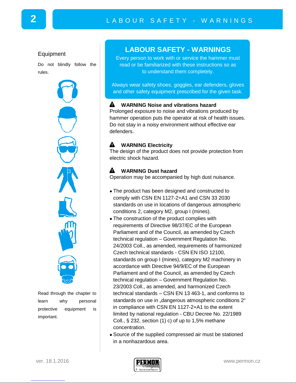
Always wear safety shoes, goggles, ear defenders, gloves
and other safety equipment prescribed for the given task.
WARNING Noise and vibrations hazard
Prolonged exposure to noise and vibrations produced by
hammer operation puts the operator at risk of health issues.
Do not stay in a noisy environment without effective ear
defenders.
WARNING Electricity
The design of the product does not provide protection from
electric shock hazard.
WARNING Dust hazard
Operation may be accompanied by high dust nuisance.
The product has been designed and constructed to
comply with CSN EN 1127-2+A1 and CSN 33 2030
standards on use in locations of dangerous atmospheric
conditions 2, category M2, group I (mines).
The construction of the product complies with
requirements of Directive 98/37/EC of the European
Parliament and of the Council, as amended by Czech
technical regulation –Government Regulation No.
24/2003 Coll., as amended, requirements of harmonized
Czech technical standards - CSN EN ISO 12100,
standards on group I (mines), category M2 machinery in
accordance with Directive 94/9/EC of the European
Parliament and of the Council, as amended by Czech
technical regulation –Government Regulation No.
23/2003 Coll., as amended, and harmonized Czech
technical standards –CSN EN 13 463-1, and conforms to
standards on use in „dangerous atmospheric conditions 2“
in compliance with CSN EN 1127-2+A1 to the extent
limited by national regulation - CBU Decree No. 22/1989
Coll., § 232, section (1) c) of up to 1,5% methane
concentration.
Source of the supplied compressed air must be stationed
in a nonhazardous area.
Equipment
Do not blindly follow the
rules.
Read through the chapter to
learn why personal
protective equipment is
important.
2

S A F E T Y I N S T R U C T I O N S
www.permon.cz
SK 9-5, 6, 6A
Only operate the hammer
with recommended,
approved tools. Work with
the recommended air
pressure and avoid heavy
impacts.
Do not get distracted –risk
of accident is always
present.
Make sure there is no
plumbing or wiring
(electricity, gas, ...) in place
of operation.
If you come across a
foreign object while
operating, put the hammer
aside and uncover the
object carefully to identify
it.
If you cannot produce
sufficient thrust on the
hammer (e.g. while
operating horizontally or
upward), choose another
type of machine or
technology. Insufficient
thrust increases vibrations
and risk of injury.
Supply hoses
• Fire-technical properties of hoses used for supplying
compressed air must comply with CBU Decree No. 22/1989
Coll., § 1ř5, section (1), as amended.
• Supply hoses used in group I (mines) areas of higher
explosion risk I M2 must meet requirements set by CBU
Decree No. 22/19ř9 Coll., § 232, section c), as amended,
and comply with requirements of enactments CSN EN
1127-1 and CSN EN 1127-2+A1 6.4.7, CSN EN 13 463-1
7.4.3, CSN 33 2030.
SAFETY INSTRUCTIONS
As the following instructions cannot cover all possibly
occurring cases, sound common sense must be employed
when working with the hammer and in the vicinity of this
machine.
Do not touch the trigger until you are ready to operate.
Always hold the hammer with both hands while
operating.
Stay on a safe and stable platform while operating.
Do not put the hammer close to your face and do not
rest it on your leg.
Do not use your leg to push the hammer down while
operating. The tool can break and cause serious
injury.
Stand with your legs safe out of the way of the tool
while maintaining balance.
Compressed air is dangerous! Do not aim an air hose
at yourself or other people. Do not use pressurized air
to clean the site or your clothing.
Make sure all hose connections are firm and airtight
and secure hoses to prevent loss of air or injury if a
hose gets loose or bursts.
Secure hoses using the prescribed number of
recommended hose clips and sockets prescribed for
the type of hose.
Do not release any joints that are under pressure.
Always switch off the air supply and bleed hoses first.
3

M A T E R I A L A N D C O N S T R U C T I O N
ver. 18.1.2016
www.permon.cz
MATERIAL AND CONSTRUCTION
Main parts of the hammer are constructed of SAE grade 11,
12 and 14 carbon steels. No materials susceptible to
ignition spark formation are used on external parts.
The hammer is also free of materials with hazardous
electrostatic charging properties. The galvanized steel
surface also meets all of the requirements above.
APPLICATION
The pick hammer is a versatile tool. It is designed for
breaking up low to medium strength rock and material
(concrete, bituminous roadways, coal etc.), in construction
works and mining or surface operations.
Technical data and main dimensions
ISO unit
SK 9-5
SK 9-6
SK 9-6A
Weight
kg
9.5
9.5
10.5
Impact energy
J
26
Impact frequency
Hz
28
Air consumption
m3min-1
1.1
Operating air pressure
MPa
0.4 –0.7
Effective value of weighted acceleration
m.s-2
9.1
Measured sound power level
dB
103.9
104.4
102.6
Guaranteed sound power level
dB
105
105
104
Length
mm
470
470
475
Width
mm
180
Supply hose
mm
Js 13, 16, 20
Connecting thread
''
G 3/4''
Tool shank size
mm
Ø25xŘ5
#22x82
#22x82
Mean values (±10% tolerance) at 0.6 MPa air pressure.
Air pressure
SK pick hammers are
constructed for operating air
pressure of 0.4 –0.7 MPa.
0.4 –0.7 M P a
4

T E C H N I C A L D E S C R I P T I O N
www.permon.cz
SK 9-5, 6, 6A
Machine type and serial
number are embossed on
the handle.
TECHNICAL DESCRIPTION
The pick hammer is constructed for operating air pressure
of 0.4 - 0.7 MPa. Compressed air is in turns filling spaces
below and above floating piston head in hammer cylinder,
setting piston into linear reciprocating motion. In power
stroke, piston transfers its kinetic energy to a tool that
disrupts material. The tool is retained by screw retainer (SK
9-5, 6) or a latch mechanism (SK 9-6A). Exhaust air leaves
through a series of holes in silencer. Silencer can be rotated
into arrested positions, directing exhaust air to ensure
safety and comfort.
MODEL LABELLING
Machines are fitted with labels containing important
information. Keep these labels clean and readable at all
times and order new ones as necessary.
The main label should be found on the handle.
The 'CE' symbol states that the product is EC-approved
(see EC-Declaration of conformity).
Maximum permitted compressed air pressure is stated in
the top right corner.
The opened book symbol states that user has to read and
understand the manual before using the machine for the
first time.
The headset symbol reminds user to wear effective ear
defenders.
The last symbol reminds user to wear safety goggles.
Guaranteed noise level in accordance with Directive
2000/14/EC is indicated by a label under silencer, and a
mark on the silencer marks the group and category the
machinery falls under in accordance with Directive 94/9/EC
–ATEX.
SK 9-5, 9-6 and 9-6A vary in
tool shank and tool retainer.
9-5
9-6
9-6A
Ø2ŘxŘ5
#22x82
#22x82
Tool shanks and
tool retainers
SK 9-6A 93/0516
5

M A I N T E N A N C E P R I N C I P L E S
ver. 18.1.2016
www.permon.cz
MAINTENANCE PRINCIPLES
Only personnel properly acquainted with the structure and
function of the hammer can service the tool.
All repairs are to be performed by the manufacturer or
authorized trained personnel.
Dry, clear air of the appropriate overpressure
(see Technical data) must be available in
sufficient volumes.
Supply hose must match the prescribed dimensions.
To avoid excessive frictional pressure loss, do not use
hoses of over 15 meters in length (in case of a Js16
hose). If necessary, hose of a larger diameter can be
used over greater distances.
Protect the hammer from dirt and other harmful
particles getting in. Always keep the input and output
openings clean.
Blow the hose clear to get rid of potentially harmful
particles before attaching it to the hammer.
Properly tighten all joints and re-tighten after 3-5 hours
of first operation.
Check-up on the state of the hammer regularly.
Hexagonal chuck in SK 9-6 and 9-6A makes use of
chisel type tools possible. The open screw retainer can
be used for wider chisels and facilitates faster tool
replacement. If the hammer operates without sufficient
thrust, the screw retainer can crack under heavy
impacts of the tool!
LUBRICATING
The hammer must be in good condition and lubricated
properly to provide maximum performance, service life and
proper functionality. Ensure sufficient lubrication with an LR
oiler or a SOOR unit.
Alternatively, pour about 100 cm3of oil into the air supply
hose (at the entry point) by the compressor unit and 5 cm3
into the air inlet at the beginning of each work shift and
repeat every 2-3 hours of operating.
Do not use hydraulic oils or unstabilized coleseed oils
for lubrication.
Before storing the tool for over three weeks, conserve
it using mineral oil (see Storing).
Do not use ecological oils for conservation.
Thrust
With regards to vibrations
and manipulation of the
hammer, the optimal thrust is
between 150 –200 N.
The thrust must prevent the
hammer from working idly,
which increases wear and
chance of breakdown.
Tool insertion
Unscrew retainer with ring.
Always check the state of
rubber ring. Insert tool into
cylinder and screw retainer
back on.
The SK 9-6A version with
latch retainer comes without
a ring. Insert tool by tilting
the latch and then close the
retainer.
Never start a hammer
without a tool inserted!
6

S T O R I N G
www.permon.cz
SK 9-5, 6, 6A
Recommended ecological oils:
BP BIOHYD SE 46, ÖMV BIOHYD M 32,
TOTAL HYDROBIO 46, TopOil BIO UNI
Recommended mineral oils:
PARAMO PNEUMAT 46
STORING
Before storing the tool for over three weeks, it needs to be
conserved.
Conserve the hammer by pouring cca. 50 cm3(0.5 dcl)
of mineral oil into the air inlet and running it shortly to
coat its internal parts with oil.
Store the hammer in dry conditions –protected from
weather factors and relative humidity below 75%.
Do not store the hammer close to corrosive chemicals
or gases.
In proper storage conditions, the hammer can be stored for
a year and spare parts for a year and a half without re-
conservation.
DELIVERING
The hammer is delivered separately, including this manual
and a certificate of warranty.
By default, we deliver the ¾'' Quick Coupling as the joint
for the supply hose. Alternatively, the quick coupling can be
replaced by a cap nut with a socket, which can be attached
to the ¾“ threaded socket.
The cap nut (item no. 319 257) can be combined with:
Ø13 socket (item no. 319 264)
Ø16 socket (item no. 319 255)
Ø20 socket (item no. 319 256)
Following items are also for sale:
tools
oilers, water separators
recommended ecological oils
hoses and hose ends, adapters, nuts, sockets, clips
Low temperatures
Presence of condensate in
air coupled with low
temperatures can cause the
hammer to freeze up.
Add an AOV 6 water
separator or the SOOR unit
before the hammer and as
far away from the
compressor unit as possible
(min. 20 m).
Ordering spare parts
All hammers are
manufactured in accordance
with drawing documentation
to ensure interchangeability
of all components.
Please state the hammer
type, name, quantity and
item no. of the desired
component in your order
form.
Example: SK 9-5
Piston 5003-475 1pc
7

P A R T S L I S T
ver. 18.1.2016
www.permon.cz
PARTS LIST
8
Pos.
Item No.
Title
Qty
Standard
9410 350
Pick hammer SK 9-5 Ø2ŘxŘ5
9410 360
Pick hammer SK 9-6 #22x82
9410 430
Pick hammer SK 9-6A #22x82
1
8323 590
Cylinder Assy. Ø25x75
1
J
1
5095 572
Cylinder
1
J
2
2005 280
Chuck Ø25xŘ5
1
J
1
8323 600
8323 920
Cylinder Subassy. # 22x82
1
J
1
5095 572
5095 861
Cylinder
1
J
2
2090 220
2090 610
Chuck #22x82
1
J
3
273 123
273 123
Rubber Sealing 4202-050
1
J
4
273 129
273 129
Rubber Ring 4201-311
1
J
5A
8042 291
8042 291
Closed Screw Retainer
1
J
5B
8042 300
Open Screw Retainer
1
N
6
8330 041
Latch Retainer Subassy.
1
J
7
5132 230
Latch Retainer
1
J
8
309 331
Screw M 12 x 65
1
J
9
311 326
Nut M 12
1
J
10
311 408
Pin 12 x 50
1
J
11
311 406
Pin 20 x 50
1
J
12
5256 102
Latch
1
J
13
315 138
Spring 4501-980
1
J
14
0900 950
Pin
1
J
15
5003 475
Piston
1
J
16
3908 060
Distribution Ring
1
J
17
1511 281
Cover
1
J
18
3051 011
Pin
1
J
19
273 406
Silencer
1
J
20
4771 050
Safety Ring
1
J
21
8040 140
Handle Assy.
1
N
22
5259 483
Handle
1
J
23
1411 172
Trigger
1
J
24
311 038
Spring Pin 8 x 28
1
J
25
722 094
Ball 17 (plastic)
1
J
26
315 007
Spring 4500-240
1
J
27
311 376
Plug
1
J
28
4087 330
Threaded Socket G 3/4''-3/4''
1
J
29
414 259
Quick Coupling 3/4''
1
J
30
3081 271
Trigger Pin
1
J
*
319 264
Socket Js 13
1
N
31*
316 255
Socket Js 16
1
N
*
319 256
Socket Js 20
1
N
32*
319 257
Cap Nut 3/4''
1
N
-
8040 160
Handle Assy. (bottom triggering)
1
N
-
5259 591
Handle
1
N
-
562 015
Trigger
1
N
-
311 377
Spring Pin 6 x 28
1
N
25
722 094
Ball 17 (plastic)
1
N
26
315 007
Spring 4500-240
1
N
27
311 376
Plug
1
N
28
4087 330
Threaded Socket G 3/4''-3/4''
1
N
29
414 259
Quick Coupling 3/4''
1
N
30
3081 271
Trigger Pin
1
N
J = Standard N = On Demand * = Replaces Quick Coupling (29)


AXONOMETRIE / AXONOMETRIC VIEW
SEZNAM ČÁSTÍ
STR. 8
PARTS LIST
PAGE 8
SK 9-5, 6, 6A
28 1
31*
32*
29

6
8
This manual suits for next models
3
Table of contents
Other Permon Power Tools manuals