Permon VK 23 User manual

OPERATION AND MAINTENANCE MANUAL
VK 23
THIS MANUAL INTO THE HANDS OF THE OPERATOR.
FAILURE TO OBSERVE THE FOLLOWING WARNINGS COULD RESULT IN INJURY.
Design, manufacture, sales & service of
pneumatic tools
PERMON s.r.o.
tel: +420 (0)313 558145
Roztoky
+420 (0)313 558271-4
27023 Křivoklát
fax: +420 (0)313 558313
CZECH REPUBLIC
email:
export@permon.cz
www.permon.cz
SEIT 1826 - SINCE 1826

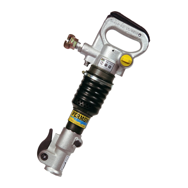
VK23 rock drill is designed for drilling through low to high strength materials in connection to an air leg. The
medium weight tool can be used for drilling holes during blasting operations in mines as well as on road
construction sites and other utility work. The recommended drilling range is 6 – 8 m with a diameter of 45 mm or
1 – 2 m with a diameter of 62 mm.
Permon is not responsible for any customer's modifications of tools for applications on which Permon was not
consulted.
PLACING TOOL IN SERVICE
• Always operate, inspect and maintain this tool in accordance with all regulations (local, state, federal and
country), that may apply to hand held/hand operated pneumatic tools.
• For safety, top performance and maximum durability of parts, operate this tool at 4 – 6 bar/400 – 600 kPa
maximum air pressure at the inlet with 1” (25 mm) inside diameter air supply hose. Apply the optimal thrust of
150 – 200 N.
• Keep the water flushing pressure at roughly 100 kPa less than the operating air pressure. The water
consumption is approximately 240 litres per hour.
• Always turn off the air supply and disconnect the air supply hose before installing, removing or adjusting any
accessory on this tool, or before performing any maintenance on this tool.
• Do not use damaged, frayed or deteriorated air hoses and fittings.
• Be sure all hoses and fittings are of the correct size and are tightly secured.
• Always use clean, dry lubricated air at 6 bar/600 kPa maximum air pressure. Dust, corrosive fumes
and/or excessive moisture can ruin the motor of an air tool.
• Do not lubricate tools with flammable or volatile liquids such as kerosene, diesel or jet fuel.
• Do not remove any labels. Replace any damaged label.
• Carrying out a check-up of the tool after 150 – 200 hours of operation is recommended.
USING THE TOOL
• Always wear eye protection when operating or performing maintenance on this tool.
• Always wear hearing protection when operating this tool.
• Keep hands, loose clothing and long hair away from the rotating end of this stool.
• Anticipate and be alert for sudden changes in motion during every start up and operation of any power tool.
• Keep your body stance balanced and firm. Do not overreach when operating this tool.
• Tool accessories may continue to impact briefly after throttle is released.
• Air powered tools can vibrate in use. Vibration, repetitive motions or uncomfortable positions may be harmful to
your hands and arms. Stop using any tool if discomfort, tingling feeling or pain occurs. Seek medical advice
before resuming use.
• Use accessories recommended by Permon.
• This tool is not designed for working in explosive atmospheres.
• This tool is not insulated against electric shock.
The use of other than genuine Permon replacement parts may result in safety hazards, decreased tool
performance, and increased maintenance, and may invalidate all warranties.
Repairs should only be executed by an authorised trained personnel. Consult your nearest Permon authorised
service centre.
SPECIFIC WARNINGS
• Always wear eye protection when operating or performing maintenance on this tool.
• Always wear hearing protection when operating this tool.
• Always turn off the air supply and disconnect the air supply hose before installing, removing or adjusting any
accessory on this tool, or before performing any maintenance on this tool.
• Do not use damaged, frayed or deteriorated air hoses and fittings.
• Air powered tools can vibrate in use. Vibration, repetitive motions or uncomfortable positions may be harmful to
your hands and arms. Stop using any tool if discomfort, tingling feeling or pain occurs. Seek medical advice
before resuming use.
• Do not carry the tool by the hose.
• Keep your body stance balanced and firm. Do not overreach while operating this tool.
• Operate at a maximum of 6.0 bar/600 kPa air pressure.
• When wearing gloves and operating models with an inside trigger, always make sure that the gloves will not
prevent the trigger from being released.
• Wear safety shoes, a hard hat, safety goggles, gloves, a dustmask and any other appropriate protective
clothing while operating the tool.

• Do not indulge in horseplay. Distraction can cause accidents.
• Keep hands and fingers away from the throttle lever until it is time to operate the tool.
• Never rest the tool or drill steel on your foot.
• Never point the tool at others.
• Compressed air is dangerous. Never point an air hose at other people or yourself.
• Never use compressed air to blow clothes free of dust.
• Be sure all the hose connections are tight. A loose hose not only leaks but can come completely off of a tool
and, while whipping under pressure, injure the operator and others in the area. Attach safety cables to all hoses
to prevent injury in case a hose is accidentally broken.
• Never disconnect a pressurised air hose. Always turn off the air supply and bleed the tool before disconnecting
a hose.
• The operator must keep limbs and body clear of the drill steel. If a drill steel breaks, the tool with the broken drill
steel projecting from the tool will suddenly surge forward.
• Do not ride the tool with one leg over the handle. An injury can occur if the drill steel breaks while riding the
tool.
• Learn what is underneath the worked material. Be alert for hidden water, gas, sewer, telephone or electric lines.
• To clean any parts of the rock drill, only use proper cleaning solvents that meet current safety and health
standards. Use the cleaning solvents in a well-ventilated area.
• Do not flush the tool or clean any of its parts using diesel fuel. Diesel fuel residue will ignite as the tool is
operated, causing damage to its internal parts. While using models with outside triggers or throttle levers, take
care to prevent accidental operation when laying the tool down.
• Do not operate a tool with broken or damaged parts.
• Never start a tool while it is lying on the ground.
• This tool is not designed for working in explosive atmospheres.
• This tool is not insulated against electric shock.
OPERATION
Lubrication
Always use an air line lubricator with these tools.
Recommended environmentally friendly oils:
TOTAL PNEUMA
SHELL TORCULA 32
Top Oil BIO Uni
Atea PNEU-EKO
Attach the lubricator as close to the tool as practical. Use the recommended LR-1 oiler or the SOOR 6 unit to
ensure sufficient lubrication. If an air line lubricator is not available, disconnect the air hose and pour about 0.5
dcl / 50 ccm of oil into the air inlet and 0.1 dcl / 10 ccm into the supply elbow of the tool at the beginning of each
work shift. Repeat after every 30 minutes of operating the machine.
For operating multiple drilling hammers at one work site, usage of the SOOR unit (for 3 hammers) or the
distribution frames R4 (for 4 hammers) or R5 (for 5 hammers) is recommended.
Before storing the tool or if the tool is to be idle for a period exceeding 3 weeks, pour about 0.5 dcl / 50 ccm of oil
into the air inlet and operate the tool shortly to coat the internal parts with oil.
Lubricate the fronthead regularly (beginning of each shift) with a water resistant grease (use grease nipple).
Do not use any of the environmentally friendly oils for conservation.
Air Supply and Connections
Always use clean, dry lubricated air. Dust, corrosive fumes and/or excessive moisture can ruin the motor of an
air tool. An air line filter can greatly increase the life of an air tool. The filter removes dust and moisture.
Make sure all hoses and fittings are tightly secured and of the correct size.
Water Supply and Connections
Always use clean water. Make sure all hoses and fittings are tightly secured and of the correct size.
Air Leg Installation
Connect the air leg to the yoke of the hammer and firmly tighten the cap nut. Check regularly during the
operation.
Recommended mineral oil:
PARAMO PNEUMAT 46

Accessory Installation
Always turn off the air supply and disconnect the air supply hose before installing, removing or adjusting any
accessory on this tool or before performing any maintenance on this tool. Failure to do so could result in an
injury.
1. Open the retainer.
2. Insert the drill rod into the hammer.
3. Close the retainer.
• Do not repair the tool at the work site. Always take the tool to a repair shop. Never drag the tool on the ground.
The air port and other openings will become clogged with dirt and debris.
• Compressed air is dangerous. Avoid pointing the hose at any of your co-workers or yourself and never use the
air to clear the worksite or work clothing.
• Do not operate the tool unless the drill steel is pushed against the worked material to avoid premature wear of
parts and reduce the vibration isolation properties of the tool.
The starting lever has 4 positions:
1/ The starting lever is perpendicular to the hammer axis – STOP
2/ The starting lever is 45 degrees forwards – SLOW DRILLING
3/ The starting lever is forwards parallel with the hammer axis – FULL DRILLING OUTPUT
4/ The starting lever is backwards – FLUSHING THE HOLE
SPECIFICATIONS
Weight kg 26,5
Length mm 720
Height mm 285
Working Pressure bar 4 – 6
Air Consumption m
3
/min 4
Impacts per Revolution – 16
Impact rate 1/min 2100
Chuck Size mm hex. 22X108
Air Supply Hose mm 25
Water Supply Hose mm 13
Torque Nm 16
DISASSEMBLING THE VK23 ROCK DRILL
GENERAL INSTRUCTIONS
• Clean the outer surface of the rock drill.
• Do not disassemble the rock drill any further than necessary to replace or repair damaged or worn parts.
• Whenever grasping the rock drill in a vice, always use leather or copper covered vice jaws to protect the
surface of the part and help to prevent distortion. Take extra care with threaded parts and housings.
• Do not remove any part that is a press fit in or on a subassembly unless the removal of the part is necessary
for repairs or replacement.
• Do not disassemble the rock drill unless a complete set of seals and o-rings is available for replacement.
All components are hold together by 2 side bolts (33). Screw out the nuts (34), remove side bolts (33) and
handle (32).
Remove the cylinder cover (51) step by step with the stirrup (52) and drill bushing (49), impact sleeve (46),
piston (2) with the tang nut (44), cylinder (1) with the pin (60), bottom distribution cover (42) with the stop (47),
distribution body (41), upper distribution cover (40), distribution ring (43), ratchet (39) with the screw driving lug
(35), pawls (36), pins (37) and springs (38).
Warning! The threads of the tang nut (44) and the carrier (50) are left-handed!

Disassembly of the flushing valve:
Screw off the plug (20) with the ring (19) from the cylinder head (3). Remove the spring (23), starting rod
(16) and the starting pin (15). If necessary, remove inner piece (14) with rings (17, 18).
Disassembly of the starting lever and air inlet:
Press out the pins (7) and remove balls (6) through the free holes – 20 pieces on the starting lever, 21 pieces on
the air inlet (8). Remove the starting lever and the air inlet.
Remove the arresting pin (5) and spring (4) from the starting lever.
Disassembly of the flushing pipes:
Screw out the nut (31) and the plug (30), remove the sealing (28), the inner piece (29), the water flushing pipe
(25) with its sealing (28), inner piece (27) and the air flushing pipe (26).
Disassembly of the air leg stirrup:
Press in the pin (58), remove ring (54) from the pin (57). Pull out the pin (58) and spring (55) from the pin (57).
Press out the pin (57) from the cylinder and release the stirrup (53).
ASSEMBLY OF THE VK23 ROCK DRILL
GENERAL INSTRUCTIONS
• Before assembling the rock drill, clean all the parts thoroughly, dry them up and carefully inspect for signs of
wear.
• Lubricate all moving parts with the recommended oil (see Lubrication).
• Replace all the rubber parts and plastic pins (7) – if removed.
• Apply a thin film of O-ring lubricant to all O-rings before final assembly.
Assembly is made the opposite way to disassembly. When inserting the distribution body (41) be careful not to
place it facing in the opposite direction. The O-ring (45) must be placed between the impact sleeve (46) and the
cylinder (1) and a pin (60) must be present between the cylinder (1) and the bottom distribution cover (42).
Nuts (34) should be tightened step by step on both sides.
After the assembly, check if the pawl mechanism is working correctly by rotating the drill bushing (49).
Run in the assembled rock drill for a short time using lower air pressure and increased lubrication.


Parts List
REF. PART NO. PART NAME QTY. REQ. NOTES
9403-470
SET VK23
1 5091-436
CYLINDER 1 J
2 5002-313
PISTON 1 J
3 5253-991
CYLINDER HEAD 1 J
4 4500-731
SPRING 1 J
5 3071-040
ARRESTING PIN 1 J
6 324393
BALL 3/16“ 41 J
7 321020
PIN 6x31 3040-690 2 J
8 4424-391
SUPPLY ELBOW R1 1 J
8 4424-100
SUPPLY ELBOW Rd 1 N
9 273034
RING O 40x32 1 J
11 9421-060
DIRECT VALVE Js13 1 J
12 319-265
SOCKET ST 25B/2 27,5 1 J
12 4023-240
SOCKET Js 25 1 N
13 319266
CAP NUT UM 10/2 1 J
13 0871-222
CAP NUT Rd40 1 N
14 0501-080
INNER PIECE 1 J
15 3040-910
STARTING PIN 1 J
16 3011-141
STARTING ROD 1 J
17 273019
RING O 10x6 1 J
18 273025
RING O 20x16 3 J
19 273090
RING O 25x21 1 J
20 0010-150
PLUG 1 J
22 273023
RING O 16x12 1 J
23 4500-721
SPRING 1 J
25 8019-060
FLUSHING PIPE 1 J
26 4307-070
AIR FLUSHING PIPE 1 J
27 4070-020
INNER PIECE 1 J
28 273173
SEALING 4201-940 2 J
29 4070-030
INNER PIECE 1 J
30 4072-020
PLUG 1 J
31 0682-030
NUT 1 J
32 1327-072
HANDLE 1 J
33 0562-850
TIGHTENING SCREW 2 J
34 311423
NUT M18x1.5 2 J
35 5151-350
SCREW DRIVING LUG 1 J
36 3792-090
PAWL 4 J
37 3043-170
PIN 4 J
38 315264
SPRING 4503-101 4 J
39 3782-111
RATCHET 1 J
40 3925-124
DISTRIBUTION COVER 1 J
41 3924-133
DISTRIBUTION BODY 1 J

42 3925-102
DISTRIBUTION COVER 1 J
43 3902-091
DISTRIBUTION RING 1 J
44 2068-320
TANG NUT 1 J
45 273036
RING O 70x3 1 J
46 2261-501
IMPACT SLEEVE 1 J
47 4207-060
STOP 1 J
49 2089-931
DRILL BUSHING 22x108 1 J
50 0441-040
CARRIER 1 J
51 5152-021
CYLINDER COVER 1 J
52 4760-100
SPRING 22x108 1 J
53 8011-062
STIRRUP 1 J
54 3140-101
PIN 1 J
55 4501-330
SPRING 1 J
57 2045-170
RING 1 J
58 3050-080
PIN 1 J
60 311198
PIN 3X12 1 J
414290
QUICK COUPLING 1 N
*J = Standard; N = Available on demand
Table of contents
Other Permon Rotary Hammer manuals