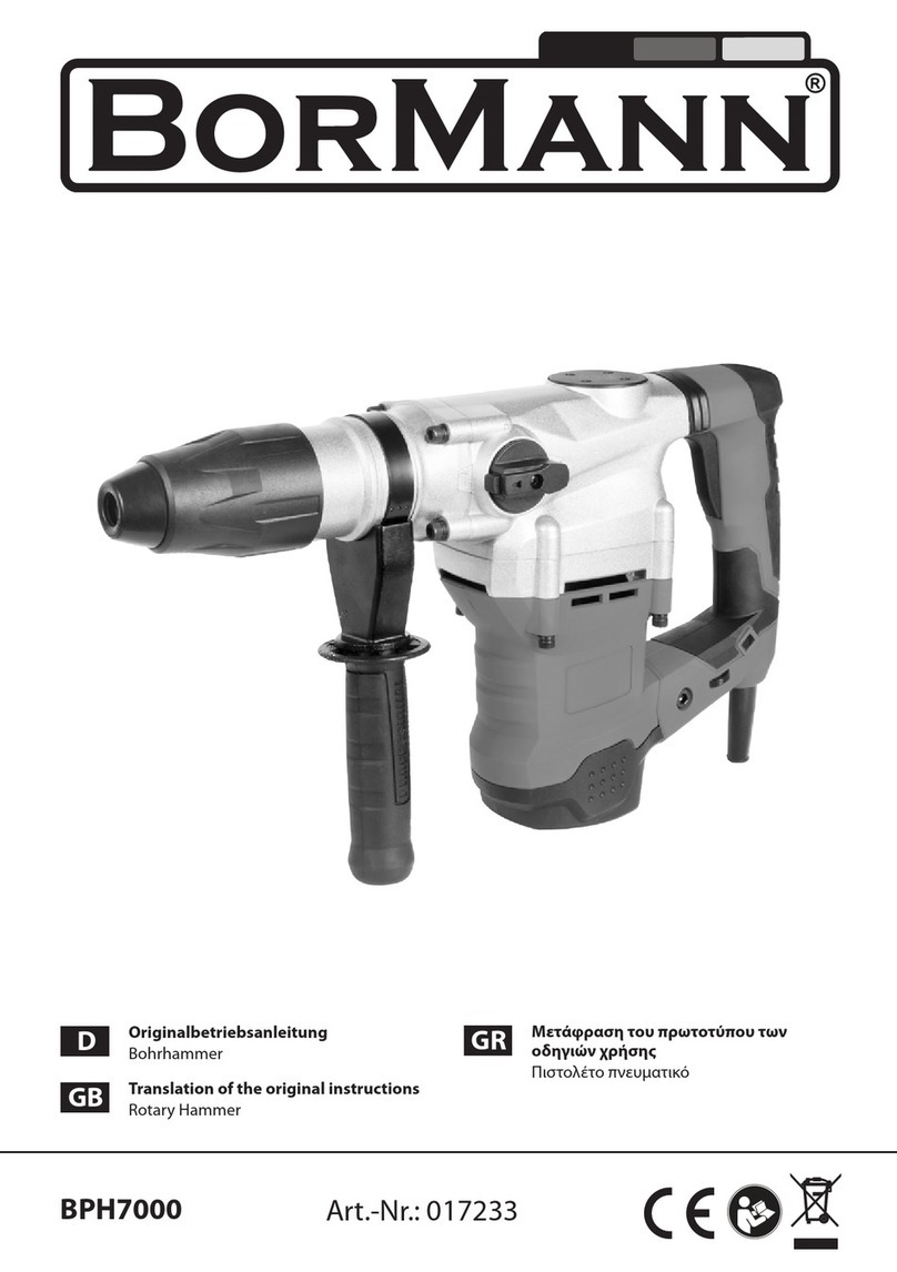
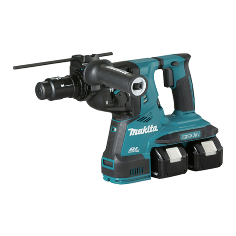
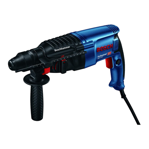
ADENDORFF MAC AFRIC SDRILC-024 User manual


GENERAL POWER TOOL SAFETY WARNINGS
(For All Power Tools)
WARNING! Read and understand all instructions.
Failure to follow all
instructions listed below may result in electric shock, fire and/or serious
personal injury.
Save all warnings and instructions for future reference.
The term “power tool” in the warnings refers to your mains-operated (corded) power tool or
battery-operated (cordless) power tool.
Work Area Safety
1.
Keep work area clean and well lit.
Cluttered or dark areas invite accidents.
2. Do not operate power tools in explosive atmospheres, such as in the presence of
flammable liquids, gases, or dust.
Power tools create sparks which may ignite the dust or
fumes.
3. Keep children and bystanders away while operating a power tool.
Distractions can cause
you to lose control.
Electrical Safety
4. Power tool plugs must match the outlet. Never modify the plug in anyway. Do not use any
adapter plugs with earthed (grounded) power tools.
Unmodified plugs and matching
outlets will reduce risk of electric shock.
5. Avoid body contact with earthed or grounded surfaces, such as pipes, radiators, ranges
and refrigerators.
There is an increased risk o electric shock if your body is earthed or
grounded.
6. Do not expose power tools to rain or wet conditions.
Water entering a power tool will
increase the risk of electric shock.
7. Do not abuse the cord. Never use the cord for carrying, pulling or unplugging the power
tool. Keep cord away from heat, oil, sharp edges or moving parts.
Damaged or entangled
cords increase the risk of electric shock.
8. When operating a power tool outdoors, use an extension cord suitable for outdoor use.
Use of a cord suitable for outdoor use reduces the risk of electric shock.
9. If operating a power in a damp location is unavoidable, use a residual current device
(RCD) protected supply.
Use of an RCD reduces the risk of electric shock.
NOTE: The term “residual current device (RCD)” may be replaced by the term “ground
fault circuit interrupter (GFCI)” or “earth leakage circuit breaker (ELCB)”.
Personal Safety
10. Stay alert, watch what you are doing and use common sense when operating a power
tool. Do not use a power tool while you are tired or under the influence of drugs, alcohol,
or medication.
A moment of inattention while operating power tools may result in serious
personal injury.
11.
Use personal protective equipment. Always wear eye protection.
Protective equipment
such as dust mask, non-skid safety shoes, hard hat, or hearing protection used for
appropriate conditions will reduce personal injuries.
12. Prevent unintentional starting. Ensure the switch is in the off-position before connecting
to power source and /or battery, picking up or carrying the tool.
Carrying power tools with
your finger on the switch or energising power tools that have the switch on invites
accidents.
13. Remove any adjusting key or wrench before turning the tool on.
A wrench or a key left
attached to a rotating part of the power tool may result in personal injury.
14. Do not overreach. Keep proper footing and balance at all times.
This enables better control
of the power tool in unexpected situations.
15. Dress properly. Do not wear loose clothing or jewellery. Keep your hair, clothing, and
gloves away from moving parts.
Loose clothes, jewellery or long hair can be caught in
moving parts.
16. If devices are provided for the connection of dust extraction and collection facilities,
ensure these are connected and properly used.
Use of dust collection can reduce
dust-related hazards.
Power Tool Use and Care
17. Do not force the power tool. Use the correct power tool for your application.
The correct
power tool will do the job better and safer at the rate for which it was designed.
18.
Do not use tool if switch does not turn it on or off.
Any power tool that cannot be

controlled with the switch is dangerous and must be repaired.
19. Disconnect the plug from the power source and/or the battery from the power tool
before making any adjustments, changing accessories, or storing power tools.
Such
preventive safety measures reduce the risk of starting the power tool accidentally.
20. Store idle power tools out of the reach of children and do not allow persons unfamiliar
with the power tool or these instructions to operate the power tool.
Power tools are
dangerous in the hands of untrained users.
21. Maintain power tools. Check for misalignment or binding of moving parts, breakage of
parts and any other condition that may affect the power tool’s operation. If damaged,
have the power tool repaired before use.
Many accidents are caused by poorly
maintained power tools.
22. Keep cutting tools sharp and clean.
Properly maintained cutting tools with sharp cutting
edges are less likely to bind and are easier to control.
23. Use the power tool, accessories and tool bits etc. in accordance with these instructions,
taking into account the working conditions and the work to be performed.
Use of the
power tool for operations different from those intended could result in a hazardous
situation.
Battery Tool Use and Care
24. Recharge only with the charger specified by the manufacturer.
A charger that is suitable
for one type of battery may create a risk of fire when used with another battery.
25. Use power tools only with specifically designated batteries.
Use of any other batteries
may create a risk of injury and fire.
26. When battery is not in use, keep it away from other metal objects like: paper clips, coins,
keys, nails, screws, or other small metal objects that can make a connection from one
terminal to another.
Shorting the battery terminals together may cause sparks, burns, or
a fire.
27.
Under abusive conditions, liquid may be ejected from the battery; avoid contact. If
contact accidentally occurs, flush with water. If liquid contacts eyes, additionally seek
medical help.
Liquid ejected from the battery may cause irritation or burns.
Service
28. Have your power tool serviced by a qualified repair person using only identical
replacement parts.
This will ensure that the safety of the power tool is maintained.
APPLICATIONS
Drilling, slotting and chiseling in concrete, rock, wall, etc.
Drilling in wood, metal, ceramics, and plastics.
SPECIFICATIONS
Power (DC) 18V
Battery Type Li-ion
Capacitor 4.0Ah 5.0Ah 6.6Ah
No-Load Speed 0-1100 r/min
Blows per Minute 0-4900 …/min
Max. Drilling Capacity
Concrete Ø 24 mm
Steel Ø 12 mm
Wood Ø 28 mm
Full Charging Time
4.0 Ah ≈90 mins
Charge current 3A
≈135mins
Charge current 2A
5.0 Ah ≈100 mins
Charge current 3A
≈150 mins
Charge current 2A
6.6 Ah ≈140 mins
Charge current 3A
≈210 mins
Charge current 2A
Net Weight
3.1 kg(battery
capacity:4.0/5.0Ah)
3.4kg(battery capacity:
6.6Ah)
※Due to the continuing program of research and development, the specifications herein are
subject to change without prior notice.
ADDITIONAL SAFETY RULES
1. To be safe, disabled, retarded, untrained people or people disable to operate
independently, including young children, are discouraged to operate the tool without
supervision. Young children should be supervised to ensure that they do not play with the
tool.

2. Check the tool and battery carefully before putting it into use. Stop operation immediately
when malfunctions be found and send the tool to be repaired by qualified serviceman. Do
not open the tool yourself.
3. Use only original MAC AFRIC SBATTR-002/004 type rechargeable Li-Ion battery for this
tool and recharge only with the MAC AFRIC SBATTR-002/004 type charger supplied with
the tool. Use of other type of battery or charger, e.g. imitated, modified or with other
brand, may result in a risk of battery burst causing personal injury and property damage.
4. Keep your hands and clothes far away from the drill chuck, or it may clamp your fingers
and clothes.
5. Always be sure to have a firm footing and be sure no one is below when using the tool in
high locations.
6. Use the attached auxiliary handle. Misuse may cause personal injury and always be sure
to hold the tool firmly.
7. Keep the workplace well-ventilated and wear appropriate protective equipment based on
the operation to avoid personal injury.
8. Keep working area clean. Blends of materials are particularly dangerous. Dust from light
alloys can burn or explode.
9. Secure the workpiece. A workpiece clamped with clamping devices or in a vice is held
more secure than by hand.
10. Do not touch the bit or parts close to the bit immediately after operation; they may be
extremely hot and could burn your skin
11. Damaged tools, accessories and deposed packages should be recycled in an
environmentally friendly way in accordance with the local law.
SAVE THESE INSTRUCTIONS.
WARNING! MISUSE or failure to follow the safety rules stated in this instruction manual may
cause serious personal injury.
IMPORTANT SAFETY INSTRUCTIONS FOR BATTERY AND
CHARGER
1. Always set the reversing switch lever in the central position (lock the switch) and
remove the battery cartridge before tool change, inspection, maintenance,
transportation, storage or something like that.
2. Always check and confirm the battery cartridge is installed properly before use.
3. It’s normal that the battery will become a little bit hotter while charging.
4. Do not charge for the damaged battery.
5. After charging, unplug the charger from power source and then remove the battery
cartridge from the charger. Do not leave the battery cartridge in the charger after the
charging cycle is completed.
6. Do not put the charged battery cartridge in the charger when the tool is not used.
7. Do not disassemble charger or battery; take it to a qualified serviceman when service or
repair is required; incorrect reassembly may result in a risk of electric shock or fire.
8. Do not short the battery cartridge.
9. Do not burn the battery. It will explode in a fire.
10. Be careful not to drop, shake or strike the battery.
11. Do not use battery as hammer. Knocking it may cause accidental short circuit, fire or
explosion.
12. Keep battery far from fire and high temperature. Never place battery on radiator or
expose it under continuous sun irradiation. There is danger of explosion.
13. Keep work area well-ventilated. Improper use of battery or damaged battery may send
out toxic gases, which can cause personal injury.
14. Overheating or overusing of the battery may cause liquid escape and come into contact
with the adjacent components. Clean such parts or replace them, if required. If electrolyte
contacts with your skin, wash the contacted area with soap firstly and then wash with
lemon juice and vinegar. If electrolyte gets into your eyes, rinse them out with clear water
and seek medical attention right away.
15. If operating time with a battery has become excessively shorter after charging, stop
operating immediately and replace with a new one or go to maintenance for inspection.
Continuous using of a worn out battery may result in a risk of overheating, possible burns
and even an explosion.

16. Do not expose battery cartridge to rain, snow or wet conditions.
17. Store battery cartridge properly:
a)Store the battery after it is fully charged
b) Store the battery only within a temperature range between 0℃and 45℃. Too hot or
too cold may damage the battery.
c)Avoid storing battery nearside paper clips, coins, keys, nails, screws, or other small
metal objects that can make a connection from one terminal to another. Shorting the
battery terminals together may cause sparks, burns, or a fire.
18. Do not dispose of damaged or worn out battery into household waste, fire or water.
19. Damaged or worn out battery/batteries should be collected, recycled or disposed of in an
environmental-friendly manner.
GENERAL DESCRIPTIONS
1.
Tool (Bit) 6. Auxiliary Handle
2. Dust Cap 7. Operating Mode Selector
3. Locking Sleeve 8. Battery
4.
Wing Bolt 9. Switch Trigger
5.
Depth Gauge 10. Reversing Switch Lever
INSTRUCTIONS FOR OPERATION
Installing or Removing the Battery
CAUTION:
Use only specified type battery. Other types/brands of batteries may burst cause personal
injury and property damage.
Always switch off the tool and set the reversing switch lever to the center position before
insertion or removal of the battery cartridge.
Do not use force when inserting or removing the battery cartridge. If the cartridge does not
slide in easily, it is not being inserted correctly.
NOTE: The battery is supplied partially charged. To ensure full capacity of the battery,
completely charge the battery in the battery charger before using the tool for the first time.
1. Installing the Battery
To install the battery firmly, insert it properly
all the way until it locks in place with a little
click. If not, it may accidentally fall out of the
tool, causing injury to you or someone
around you. Avoid overexerting or
hammering the battery into the motor
housing with the help of other objects. (Fig.1)
2. Removing the Battery
To remove the battery, press the unlocking
buttons on both sides of the battery and
pull out the battery along the arrow direction.
(Fig.2)

Battery Indicator Light
CAUTION:
The four charging lights may flash in red color
if the tool is overheated or overloaded. As
temperature recovers or over-load protection
is removed, press the switch and the tool can
be started normally.
Current power of the battery will be indicated
by the battery indicator light when pressing
the battery button or switching on the tool.
(Fig. 3)
Four red LED lights are set to indicate the battery power which can be referred to the following
table.
Status of Red LED Lights Approx. Battery Power Left
4 lights lit 75%~100%
3 lights lit 50%~75%
2 lights lit 25%~50%
1 light lit 10%~25%
1 light flickered Low level
Battery Charging
1. Battery Charger
Notice:
The charger applies to charge for specified Li-ion Battery under normal circumstances.
Make sure that the AC voltage of the power source meets the requirement specified on the
nameplate of the charger.
Due to the continuing program of research and development, the specifications herein are
subject to change without prior notice.
2. Charging Operation
1. Plug the battery charger into the proper AC power source. The charging indicator light will
flicker in green color and the charger operates in standby mode.
2. Insert the battery pack fully into the
battery charger and the charger starts
charging.
The battery charger can detect some sort of
failure caused by the battery and indicates by
the statuses of the red and green indicator
lights.
When a failure occurs, remove the battery
and then insert it into the charger again. If the failure continues, change with a new battery. If
the new battery can be charged, then the old battery maybe damaged. If the charging indicator
lights indicate same failure as before while changing with a new battery, then the charger
maybe damaged, take the charger to be repaired by qualified serviceman. (Fig. 4)
The following chart lists the relations between the statuses of charging and charging indicator
lights.
Descriptions of
Charging Status Icons
Icons of Charging
Indicator Lights Descriptions of Charging
Indicator Lights
Green
Light
Red
Light
Plug the charger into
a proper outlet Green light flickers, red light
extinguished
During charging
Green light extinguished, red
light keeps flickering
steadily
Charge complete
Green light keeps up
steadily, red light
extinguished
Abnormity occurs on
the battery
Green and red light flicker
alternately
The temperature of
the battery is under
0℃or higher than
Green light extinguished, red
light flickers

Switch Action
CAUTION:
Before inserting the battery cartridge into the tool, always check to see that the switch
trigger actuates properly and returns to the “OFF” position when released.
Do not operate the machine at a low
speed for too long, or the inside machine
may be overheated
To start the tool, simply pull switch trigger.
Tool speed is increased by increasing pressure
on the switch trigger and further pressure
results in an increase in speed. Release the
switch trigger to switch off the tool. (Fig. 5)
Reversing Switch Action
CAUTION:
Always check the direction of rotation before operation.
Use the reversing switch lever only after the tool comes to a complete stop. Changing
the direction of rotation before the tool stops may damage the tool. When not operating
the tool, always set the reversing switch lever to the neutral position
Never force to pull the switch trigger while the the reversing switch lever is set to the
center position.
Clockwise Rotation
Depress the reversing switch lever from side B
to side A for clockwise rotation. (view
forwards).
Counterclockwise Rotation
Depress the reversing switch lever from side A
to side B for counterclockwise rotation. (Fig 6)
When set the reversing switch lever to the
neutral position, the button is locked, and
cannot be pressed
Installing or Removing Drill Bit
Apply a small amount of bit grease on the drill bit shank head beforehand, about 0.5-1 g, to
ensure smooth action of the chuck and prolong its service life.
CAUTION:
Before operation, always set the reversing
switch lever in the central position and
remove the battery. Mustn’t press switch
trigger.
Clean the bit shank and apply bit grease
before installing the bit. Insert the bit into the
tool. Turn the bit and push it in until it
engages. (Fig. 7)
Demount the drill bit if it cannot be pushed
into. Pull down the locking sleeve several
times, and insert into the drill bit again. Turn
the bit and push it in until it engages.
Pull the drill bit to check that it is locked
correctly.
To remove the bit, push back the locking
sleeve and remove the bit (Fig. 8)
Model FFCL18-01
FFCL18-03
SCHARG-001
(FFCL18-04) FFCL18-05
Input Voltage (AC) 220-240V 110-240V 220-240V
Charging Current 3.0A 2.0A
Input Power Frequency 50-60Hz
Applicable Battery Cartridge Voltage (DC) 18V
Full Charging Time
4.0Ah ≈90min ≈135min
5.0Ah ≈100min ≈150min
6.6Ah ≈140min ≈210min
Insulation Grade Double Insulation

Auxiliary Handle
Always use the auxiliary handle to ensure operating
safety. Make sure that the auxiliary handle is on the
appointed place of the tool, and is tightened securely.
The auxiliary handle can be adjusted to any angle by
loosening it counterclockwise. (Fig. 9)
Setting Operating Mode
The Operating mode can be changed by turning the
operating mode selector.
1. Hammer Operation
Turn the operating mode selector (without pressing the
lock button), and align the triangle symbol △with the
as shown in the figure, then the tool is set in
hammer operation. Set like this when drilling on the
concrete or stone, and use carbide bits. (Fig. 10)
2. Drill Operation
Turn the operating mode selector (without pressing the
lock button), and align the triangle symbol △with the
as shown in the figure, then the tool is set in drill
operation. Set like this when drilling on the wood, metal,
or plastic, and use twist bits or solid center bits. (Fig. 11)
3. Demolition Operation
Turn the operating mode selector (without pressing the
lock button), and align the triangle symbol △with the
as shown in the figure, then the tool is set in
demolition operation. Set like this when chiseling,
scaling or demolishing, and use chisel, scaling chisel and
so on. (Fig. 12)
Bit Angle
When using the tool for demolition operation, to
change the drill angle, turn the operating mode
selector (without pressing the lock button), and
align the triangle symbol △with . Adjust the
bit to the desired angle, and then return the
operating mode selector to the symbol. (Fig.
13)
Depth Gauge
The depth gauge enables the drilling depth to be
set for convenient drilling holes of uniform depth.
Loosen the auxiliary handle, and insert the linear
part of the depth gauge into the fitting hole of the
clip board. (Fig. 14)
Move the depth gauge to the desired depth and
secure it by rotating the auxiliary handle
clockwise
.Drilling Action
1. Hammer Drill Operation
CAUTION:
Applying more pressure will not speed up the drilling. In fact, this excessive pressure will
damage the drill bit, decrease the tool performance, and shorten the service life of the tool.
There is a tremendous force exerted on the bit at the time of hole breakthrough. Be careful
and hold the tool firmly when the bit begins to break through the workpiece.
A stuck bit can be removed simply by setting the reversing switch to reverse rotation in
order to back out. Hold the tool firmly before starting the tool to remove the bit easily.
Do not drill in the material that may contain nails or something that may hamper or destroy
the drill bit.
-14-

Set the operating mode selector to the symbol, and position the bit at the desired location for
the hole, then pull the switch trigger.
Eccentricity in the bit rotation may occur while operating the tool with no load. The tool
automatically centers itself during operation. This does not affect the drilling precision.
2. Chipping/Scaling/Demolition
Set the operating mode selector to the symbol.Hold the tool firmly with both hands. Turn
the tool on and apply slight pressure on the tool so that the tool will not bounce around,
uncontrolled. Pressing very hard onthe tool will not increase the efficiency.
3. Drilling in wood or metal
SDS-plus hammer drill bit and the chuck
adapter can be used when drilling on the
steel, wood or plastic. Screw the drill chuck
in the connecting rod and tighten the lock
screw. Then insert the connecting rod into
the collect in the same way as installing
SDS-plus hammer drill bit. (Fig. 15)
The drill chuck and the chuck adapter are
optional accessories and sold separately.
Continuous Use
If the tool is operated continuously until the battery cartridge has discharged, allow the tool to
rest for 15minutes before proceeding with a fresh battery.
Overload Protection
The motor will stop if it is overload during the operation. Release the switch button then push
it to start the tool again.
Over Temperature Protection
Overload is not allowed during the operation of the tool. The electronic control system will
stop the tool when it is overload or the temperature is over 75℃.
Deep Discharging Protection
The tool is equipped with a protective circuit to protect the battery against deep discharging.
When the battery is near to be empty, the protective circuit actuates to switch off the tool.
Disposal of Battery
Lithium ion battery is contained in the battery pack. For environmental protection, recycle or
dispose of the worn out battery properly. Please consult with your local relevant departments
about how to recycle and/or dispose of the worn out battery.
To recycle or dispose of the worn out battery:
a) Remove the battery from the tool when it is worn out.
b) Wrap the terminals with a strong tape to avoid short-circuit and electric leakage.
Never attempt to disassemble or disembowel the battery!
MAINTENANCE AND INSPECTION
CAUTION:
Always be sure that the tool is switched off and the battery is removed before attempting to
perform inspection or maintenance.
Cleaning Ventilation Slots
For safe and proper working, always keep the power tool and its ventilation slots clean. Use a
soft, clean and dry brush to clean the ventilation slots regularly or when they’re clogged.
Inspecting the Mounting Screws
Regularly inspect all mounting screws and ensure that they are properly tightened. Should
any of the screws be loose, retighten them immediately. Failure to do so could result in
serious hazard.
Cleaning
Only use soft and dry cloth to wipe the body of the tool. Do not clean the tool with wet cloth,
thinner, gasoline or other volatile solvents.
-16-
-17-

EXPLANATION OF GENERAL VIEW
1
Dustproof Cover 28 O Ring
2
Circlip for Shaft 29 O Ring
3
Washer 30 Adaptor Sleeve
4
Locking Sleeve 31 Roundwire Snap Ring for Hole
5
Roundwire Snap Ring 32 Clamping Ring
6
Clamping Ring 33 Washer
7
Steel Ball 34 Clutch Spring
8
Dead Plate 35 Clutch Gear
9
Compression Spring 36 Clutch Plate
10
Lock Pin 37 Pin
11
O Ring 38 Striker
12
Retainer Sleeve 39 O Ring
13
Seal Ring 40 Piston
14
Thrust Ring 41 Washer
15
Impact Bolt 42 Piston Pin
16
Pan Head Tapping Screw 43 Shaft Sleeve
17
Gear Housing 44 Gear Housing Cover
18
Seal Ring 45 O Ring
19
Ball Bearing 46 Seal Ring
20
Needle Bearing Cover 47 Deep Groove Ball Bearing
21
Needle Bearing 48 Bearing Retainer
22
Metal Sheet for Fix 49
Cross Recessed Countersunk Head
Screw
23
Pan Head Tapping Screw 50 O Ring
24
Roundwire Snap Ring for Shaft 51 Gear Shaft
25
Cylinder 52 Front Cover
26
Retaining Ring for Hole 53 Pan Head Tapping Screw
27
Guide Sleeve 54 Hall Plate

EXPLANATION OF GENERAL VIEW
55
Ball Bearing 82 Auxiliary Handle
56
Armature Assembly 83 Left-half Handle
57
Bearing Shim 84 Right-half Handle
5
8 Ball Bearing 85 Pan Head Tapping Screw
59
Stator Assembly 86 Operating Mode Selector
60
Rear Cover 87 O Ring
61
Pan Head Tapping Screw 88 Selector Lever
62
Spline Shaft 89 Spring
63
Ball Bearing 90 Slider
64
Retainer 91 Reversing Switch Lever
65
Buckle 92 Switch
66
Metal Sheet for Support 93 Switch Trigger
67
Needle Bearing 94 Main Control Panel
68
Pendulum Bearing 95 Damping Ring
69
Needle Bearing 96 Terminal Block
70
Gear 97 Rubber Pin
71
Spring 98 Battery Cartridge
72
Pressing Block 99 Nameplate
73
Bush 100 Sticker
74
Rubber Pad 101 Battery Charger
75
Depth Gauge
76
Tightening Screw
77
Hex Nut M6
78
Compression Plate
79
Steel Band
80
Trapezoid Square-neck Bolt
81
Steel Band Base
Table of contents