Permon SK 9-5 User manual

OPERATION AND MAINTENANCE MANUAL
SK 9-5, SK 9-6, SK 9-6A,
SK 13B, SK 13D, SK 13DZ
IMPORTANT SAFETY INFORMATION ENCLOSED. READ THIS MANUAL BEFORE
OPERATING TOOL.
IT IS THE RESPONSIBILITY OF THE EMPLOYER TO PLACE THE INFORMATION IN
THIS MANUAL INTO THE HANDS OF THE OPERATOR.
FAILURE TO OBSERVE THE FOLLO ING ARNINGS COULD RESULT IN INJURY.
PERMON s.r.o. tel: +420 (0)313 558145
Roztoky +420 (0)313 558271-4
27023 Křivoklát fax: +420 (0)313 558313
CZECH REPUBLIC email: [email protected]
www.permon.cz
SEIT 1826 - SINCE 1826
esign, manufacture, sales & service
of pneumatic tools

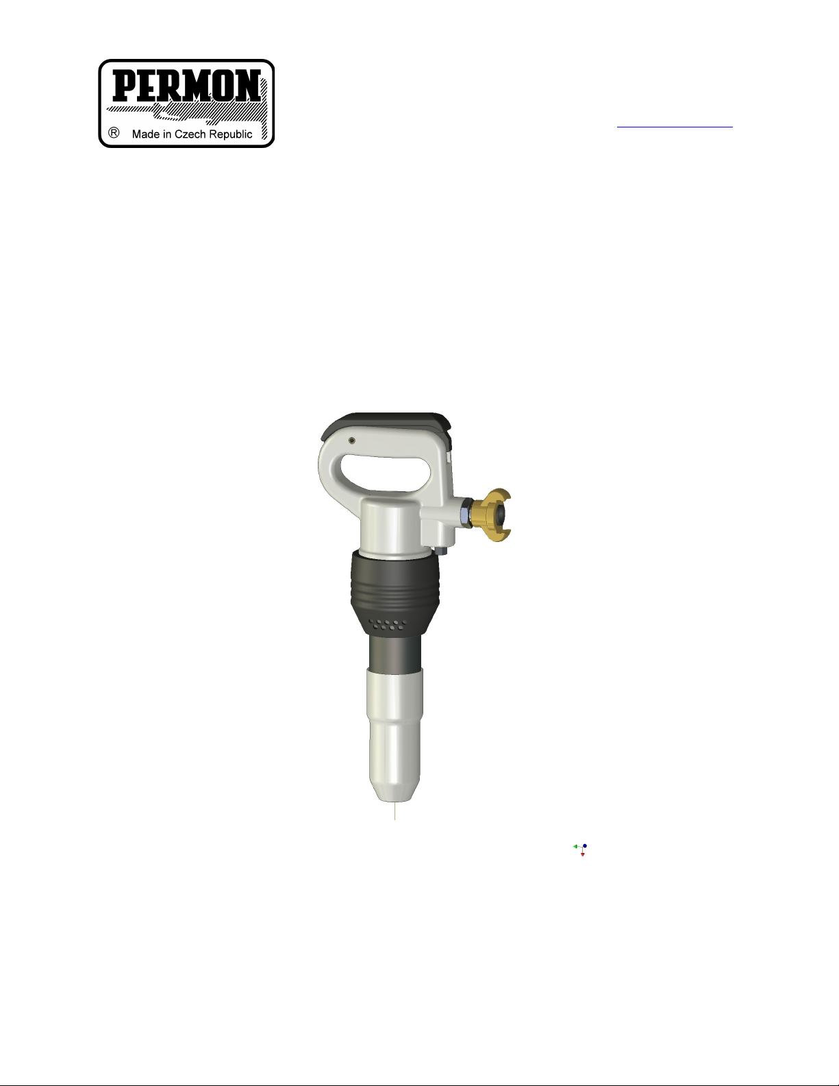
SK 9-5, SK 9-6, SK 9-6A, SK 13B, SK 13 and SK 13 Z Pick Hammers are designed for the
disintegration of low to medium strength materials (e.g. concrete, masonry bituminous asphalt etc).
Permon is not responsible for customer modifications of tools for applications on which Permon was not
consulted.
PLACING TOOL IN SERVICE
• Always operate, inspect and maintain this tool in accordance with all regulations (local, state, federal and
country), hat may apply to hand held/hand operated pneumatic tools.
• For safety, top performance, and maximum durability of parts, operate this tool at 6.0 bar/600 kPa
maximum air pressure at the inlet with 3/4” (19 mm) inside diameter air supply hose.
• Always turn off the air supply and disconnect the air supply hose before installing, removing or adjusting
any accessory on this tool, or before performing any maintenance on this tool.
• o not use damaged, frayed or deteriorated air hoses and fittings.
• Be sure all hoses and fittings are the correct size and are tightly secured.
• Always use clean, dry lubricated air at 6.0 bar/600 kPa maximum air pressure. ust, corrosive fumes
and/or excessive moisture can ruin the motor of an air tool.
• o not lubricate tools with flammable or volatile liquids such as kerosene, diesel or jet fuel.
• o not remove any labels. Replace any damaged label.
USING THE TOOL
• Always wear eye protection when operating or performing maintenance on this tool.
• Always wear hearing protection when operating this tool.
• Keep hands, loose clothing and long hair away from rotating end of tool.
• Anticipate and be alert for sudden changes in motion during start up and operation of any power tool.
• Keep body stance balanced and firm. o not overreach when operating this tool.
• Tool accessories may continue to impact briefly after throttle is released.
• Air powered tools can vibrate in use. Vibration, repetitive motions or uncomfortable positions may be
harmful to your hands and arms. Stop using any tool if discomfort, tingling feeling or pain occurs. Seek
medical advice before resuming use.
• Use accessories recommended by Permon.
• This tool is not designed for working in explosive atmospheres.
• This tool is not insulated against electric shock.
The use of other than genuine Permon replacement parts may result in safety hazards, decreased tool
performance, and increased maintenance, and may invalidate all warranties.
Repairs should be made only by authorised trained personnel. Consult your nearest Permon authorised
service center.
ARNINGS
• Always wear eye protection when operating or performing maintenance on this tool.
• Always wear hearing protection when operating this tool.
• Always turn off the air supply and disconnect the air supply hose before installing, removing or adjusting
any accessory on this tool, or before performing any maintenance on this tool.
• o not use damaged, frayed or deterlorated air hoses and fittings.
• Air powered tools can vibrate in use. Vibration, repetitive motions or uncomfortable positions may be
harmful to your hands and arms. Stop using any tool is discomfort, tingling feeling or pain occurs. Seek
medical advice before resuming use.
• o not carry the tool by the hose.
• Keep body stance balanced and firm. o not overreach when operating this tool.
• Operate at 6.0 bar/600 kPa maximum air pressure)
• When wearing gloves and operating models with inside trigger, always be sure that the gloves will not
prevent the trigger from being released.
• Wear safety shoes, hard hat, safety goggles, gloves, dustmask and any other appropriate protective
clothing while operating the tool.
• o not indulge in horseplay. istraction can cause accidents.

• Keep hands and fingers away from the throttle lever until it is time to operate the tool.
• Never rest the tool or chisel on your foot.
• Never point the tool at anyone.
• Compressed air is dangerous. Never point an air hose at yourself or co–workers.
• Never blow clothes free of dust with compressed air.
• Be sure all hose connections are tight. A loose hose not only leaks but can come completely off the tool
and while whipping under pressure, can injure the operator and others in the area. Attach safety cables to
all hoses to prevent injury in case a hose is accidentally broken.
• Never disconnect a pressurised air hose. Always turn off the air supply and bleed the tool before
disconnecting a hose.
• The operator must keep limbs and body clear of the chisel. If a chisel breaks, the tool with the broken
chisel projecting from the tool will suddenly surge forward.
• o not ride the tool with one leg over the handle. Injury can result if the chisel breaks while riding the
tool.
• Know what is underneath the material being worked. Be alert for hidden water, gas, sewer, telephone or
electric lines.
• Use only proper cleaning solvents to clean parts. Use only cleaning solvents, which meet current safety
and health standards. Use cleaning solvents in a well-ventilated area.
• o not flush the tool or clean any parts with diesel fuel. iesel fuel residue will ignite in the tool when the
tool is operated, causing damage to internal parts. When using models with outside triggers or throttle
levers, take care when setting the tool down to prevent accidental operation.
• o not operate the tool with broken or damaged parts.
• Never start the tool when it is lying on the ground.
• This tool is not designed for working in explosive atmospheres.
• This tool is not insulated against electric shock.
OPERATION
Lubrication
Always use an air line lubricator with these tools.
Recommended environmentally friendly oils:
SETUZA PRIMOL EKO PNEU
BP BIOHY SE46
ÖMV BIOHY M 32
TOTAL HY ROBIO 46
Attach the lubricator as close to the tool as practical. After each two or three hours of operation and at the
beginning of each work shift, if an air line lubricator is not used, disconnect the air hose and pour about 3
cc of oil into the air inlet of the tool.
Before storing the tool or if the tool is to be idle for a period exceeding twenty-four hours, pour about 3 cc
of oil into the air inlet and operate the tool for 5 seconds to coat the internal parts with oil.
Air Supply and Connections
Always use clean, dry lubricated air. ust, corrosive fumes and/or excessive moisture can ruin the motor
of an air tool. An air line filter can greatly increase the life of an air tool. The filter removes dust and
moisture.
Make sure all hoses and fittings are the correct size and are tightly secured.
The tool is shipped from the factory with 3/4” G male inlet thread.
Accessory Installation
Always turn off the air supply and disconnect the air supply hose before installing, removing or adjusting
any accessory on this tool or before performing any maintenance on this tool. Failure to do so could result
in injury.
For Screwed retainer:
1. Screw out the retainer.
2. Check the rubber ring in the retainer and replace it if worn. Missing or worn ring could result in retainer
breakage.

3. Insert chisel into the hammer.
4. Screw on firmly the retainer.
For Latch Type Retainer:
1. Operate the Latch until it is approximately 90 degrees to the body of the tool and clicks into position.
2. Insert the accessory into the tool until the collar of the accessory is past the Latch.
3. Operate the Latch until it is parallel to the tool and it clicks into position.
15 kg is the recommended amount of downforce to apply to the tool when working. The amount of
downforce is correct when the tool hits rhythmically, is comfortable to hold and works efficiently.
• o not repair the tool at the work site. Always take the tool to a repair shop. Never drag the tool on the
ground. The air port and other openings will become clogged with dirt and debris.
• Compressed air is dangerous. When blowing the line clear of dirt, wear eye protection and keep the air
line directed toward a safe, clear area.
• Always blow out the air line before using to clear the line of dirt.
• o not operate the tool unless the chisel is against the work since this will cause premature wear of parts
and reduce the vibration isolation properties of the tool.
• Always break material to the point of “give.” Cracking does not result in a complete break. Clear away
rubble as it is broken since uncleared rubble blocks the point of “give.”
• Always take the right size “bite” with the tool. When working new material, experiment to find the right
size “bite” required for breaking that material efficiently.
• If “bites” are too big, the operator will try to pry with the tool. This could break the chisel.
• The tool is designed for demolition, not prying. Always use a pick for prying. If “bites” are to small, the
operator will be working too slowly.
• If the chisel or accessory should become stuck, do not use excessive force or mechanical means on the
tool to pull out the chisel. oing so will damage the vibration isolation unit. Break out the stuck chisel with
a spare chisel or tool.
DISASSEMBLING THE SK9 AND SK13 PICKHAMMERS
General instructions
•Clean the Pickhammer outer surface.
•o not disassemble the pickhammer any further than necessary to replace or repair damaged or worn
parts.
•Whenever grasping a pickhammer or a part in a vice, always use leather or copper-covered vice jaws
to protect the surface of the part and help prevent distortion. Take extra care with threaded parts and
housings.
•o not remove any part that is a press fit in or on a subassembly unless the removal of the part is
necessary for repairs or replacement.
• Do not disassemble the pickhammer unless a complete set of O-rings is available for
replacement.
Disassembly of the Fronthead
Screw retainer models
Unscrew retainer (12) off the cylinder (1) and remove chisel buffer (13) from inside retainer. Remove seal
ring (8) from its groove in the cylinder.
Latch retainer models
Remove nut (17) and fronthead pinch bolt (16) from the fronthead (15). Lightly tap the fronthead (using a
hide mallet if necessary) off the cylinder (1).
Press or drift out the two fronthead spring pins (18, 19) and remove the latch lever (20).
The plunger (22) and plunger spring (21) can be removed from the fronthead.

Main Disassembly
Grip handle body (24) firmly in a vice (use leather or copper covered vice jaws).
Remove muffler retaining clip (10) from its groove in the cylinder (SK9 models only).
Insert three or four pieces of thin sheet steel approximately 8 mm wide, beneath the retaining lip of the
muffler moulding (9) (small diameter end). These will allow the rubber retaining lip of the muffler to slide
along over the groove in the cylinder and ease removal of the muffler.
Slide off muffler (9) over the cylinder exposing the cylinder flats.
Remove locking pin (7) from its hole in cylinder, the pin is provided with an M4 internal thread to assist
removal.
Remove the handle from the vice, invert the pickhammer and grip the flats of the cylinder in the
vice. Use a pipe about 1.5 Meters long positioned through the loop of the handle to first loosen
and then completely unscrew the handle assembly from the cylinder and remove. – Warning –
once the handle is unscre ed from the cylinder the piston and valve parts ill be free to fall and
could cause injury.
Handle Disassembly
Grip handle body (24) in leather or copper covered vice jaws and unscrew throttle valve plug (29) using a
13 mm spanner.
Withdraw throttle spring (28), throttle ball (27) and throttle pin (32).
Remove the trigger (25) by pressing or drifting out trigger pin (26).
Unscrew quick release coupling (31) from inlet bushing (30).
The inlet bushing (30) can be removed if required though it is assembled into the handle using a high
strength retainer and disassembly is not normally necessary.
Cylinder Disassembly
Remove the spacing washer (6) and valve plate (5).
Slide off valve ring (4) from cylinder (1).
Allow piston (3) to slide out of the cylinder bore and be caught.
The nozzle (2) is pressed into the cylinder and retained with Loctite 601 – do not disassemble unless
replacement is necessary.
ASSEMBLY OF THE SK9 AND SK13 PICKHAMMERS
General Instructions
• Before assembly of the pickhammer, clean all parts thoroughly and lubricate surfaces with a thin film
of recommended oil – (see lubrication).
• Apply a thin film of O-ring lubricant to all O-rings before final assembly.
• It is recommended that the assembly of the nozzle (2) be carried out by the manufacturer or
authorised distributor.
• The existence of a piston air cushion should be determined. Hold the cylinder vertically and allow the
piston to drop down the bore small diameter first. An air cushion is present if the piston “bounces”, at
the bottom of the cylinder and no metal to metal contact noise can be heard. If a cushion is not
present contact your authorised Permon repair centre for advise.
Cylinder assembly
Grip the cylinder (1) vertically in a vice protected with leather or copper covered vice jaws.
Lubricate and insert the piston (3) small end first into the bore. Check for air cushion.
Lubricate and slide the valve ring (4) onto the cylinder and replace the valve plate (5).
Replace the spacing washer (6) on top of the valve plate.

Handle assembly
Position trigger (25) in its slot in the handle body and align the holes in each part.
rift or press home the trigger pin (26). Check the throttle lever is free to move easily.
Grip the handle body (24) in a vice protected with leather or copper covered vice jaws.
Lubricate and insert throttle pin (32) into position reduced diameter out of the hole.
Replace the throttle ball (27) and throttle spring (28) and retain in place with throttle valve plug (29), apply
Loctite 243 to the threads of the plug and screw home fully.
If the air inlet (30) has been removed, refit it into the handle body using Loctite 243 and screw home fully.
Replace the quick release coupling (31).
Main assembly
Firmly grip the cylinder assembly vertically across the flats, in a vice protected with leather or copper
covered vice jaws.
Check for correct location of the valve ring (4) valve plate (5) and spacing washer (6).
Carefully lower the handle assembly (23) onto the cylinder and engage the threads. Tighten the handle
down by hand.
Fully tighten the handle using the 1.5 meters long pipe until the lock pin (7) can be replaced in position –
thread to the outside.
Slide the muffler (9) down the cylinder until the muffler retaining lip engages with the groove in the
cylinder. Replace the retaining clip (10) in its groove in the cylinder (SK9 models only).
Assembly of the fronthead – Scre retainer models
Replace the sealing ring (8) in its groove in the cylinder.
Inspect the chisel buffer (13) for wear and replace if necessary, by sliding a new buffer into the retainer.
Screw the retainer onto the cylinder assembly.
Assembly of the fronthead – Latch retainer models
Grease the latch plunger (22) and plunger spring (21) and insert them into position in the fronthead (15).
Locate the latch lever (20) with the holes in the fronthead and press or drift into place the fronthead spring
pins (18,19).
Check the operation of the latch.
Slide the fronthead (15) onto the end of the cylinder and align the bolt hole with the groove machined in
the cylinder.
Fit fronthead screw (16) and secure with fronthead nut (17) tighten to 90 Nm (66.4 lbs.ft) torque.
Assembly checks
Following service or repair the pickhammer should be checked for correct operation before being sent
back to the job site.
Fit the correct size accessory into the pickhammer and connect to an airline. Using low pressure 2 bar
(30psi) check to ensure the pickhammer is free of air leaks around the inlet connection and also that the
pickhammer does not automatically start to operate without the trigger being depressed.
Increase the air pressure to 6 bar (90psi) and run the tool in short bursts to check the tools starts and
stops cleanly and without hesitation.
Pickhammer operating frequency should be as given in the specification table at the end of this manual.

SPECIFICATIONS
SK 9-5 SK 9-6 SK 9-6A
Weight kg 9 9 10
Length mm 470 470 470
Width mm 236 236 236
Max. Working Pressure bar 4-7 4-7 4-7
Air Consumption m3/min 0,9 0,9 0,9
Impact Rate 1/min 1620 1620 1620
Chuck Size mm φ25x75 22 hex. x 82 22 hex. x 82
Vibration Level m/s 13,32 m/s213,32 m/s213,32 m/s2
Guarranteed Noise Level LWA 105 105 105
SK 13B SK 13D SK 13DZ
Weight kg 12,5 12,5 13,5
Length mm 612 612 612
Width mm 236 236 236
Max. Working Pressure bar 4-7 4-7 4-7
Air Consumption m3/min 0,9 0,9 0,9
Impact Rate 1/min 1260 1260 1260
Chuck Size mm φ25x75 22 hex. x 82 22 hex. x 82
Vibration Level m/s 9,10 m/s29,10 m/s29,10 m/s2
Guarranteed Noise Level LWA 105 105 105


PARTS LIST
Ref. Part No. Part Name Qty.
9410350 Pickhammer SK 9-5
9410360 Pickhammer SK 9-6
9410430 Pickhammer SK 9-6A
9410490 Pickhammer SK 13-B
9410500 Pickhammer SK 13-D
9410510 Pickhammer SK 13-DZ
1 8323590 8323860 Cylinder Assy. R25x75 1
2 2005280 2001610 Nozzle R25x75 1
1 8323600 8323920 8323870 8323880 Cylinder Assy. S22x82 1
2 2090220 2090610 2090751 2090751 Nozzle H22x80 1
3 5003472 5003472 5003472 5003690 5003690 5003690 Piston 1
4 3908060 3908060 3908060 3908140 3908140 3908140 Ring 1
5 1511280 1511280 1511280 1511280 1511280 1511280 Cover 1
6 315111 315111 315111 315111 315111 315111 Belleville washer 1
7 3051011 3051011 3051011 3051011 3051011 3051011 Pin 1
8 273123 273123 273123 273123 Ring 1
9 273406 273406 273406 1730142 1730142 1730142 Muffler 1
10 4771050 4771050 4771050 Lock Ring 1
12 8042291 8042291 8042291 8042291 Retainer 1
13 273129 273129 273129 273129 Ring 1
14 8330041 8330041 Fronthead Assy. 1
15 5132230 5132230 Fronthead 1
16 309331 309331 Screw 1
17 311326 311326 Nut 1
18 311408 311408 Pin 12x50 1
19 311406 311406 Pin 20x50 1
20 5256102 5256102 Latch 1
21 315138 315138 Spring 1
22 0900950 0900950 Pin 1
23 8040140 8040140 8040140 8040140 8040140 8040140 Handle Assy. 1
24 5259483 5259483 5259483 5259483 5259483 5259483 Handle 1
25 1411172 1411172 1411172 1411172 1411172 1411172 Trigger 1
26 311038 311038 311038 311038 311038 311038 Spring Pin 8x28 1
27 722094 722094 722094 722094 722094 722094 Ball 1
28 315007 315007 315007 315007 315007 315007 Spring 1
29 0047070 0047070 0047070 0047070 0047070 0047070 Plug 1
30 4087330 4087330 4087330 4087330 4087330 4087330 Socket 3/4"-3/4" 1
31 414259 414259 414259 414259 414259 414259 Quick Coupling 3/4" 1
32 3081271 3081271 3081271 3081271 3081271 3081271 Starting Pin 1
42 548082 548082 548082 Clamp 1
This manual suits for next models
11
Table of contents
Other Permon Rotary Hammer manuals