manuals.online logo
Brands
  1. Home
  2. •
  3. Brands
  4. •
  5. Perreaux
  6. •
  7. Amplifier
  8. •
  9. Perreaux 200 MkII User manual

Perreaux 200 MkII User manual

200 MkII
200W Stereo Power Amplifier
Owners Manual
1
Perreaux Industries Limited makes no warranty for the use of its products, other than those
expressly contained in the warranty detailed herein. The Company assumes no responsibility for
any errors which may appear in this document, reserves the ri ht to chan e products or
specifications detailed herein at any time without notice, and does not make any commitment to
update the information contained herein. No licenses to patents or other intellectual property of
Perreaux are ranted by the Company in connection with the sale of Perreaux products, expressly or
by implication.
mboob^ru
®
is a re istered trademark of Perreaux Industries Ltd.
Terms and product names in this document may be trademarks of others.
2
This pa e has intentionally been left blank.
3
i
ii
i
Introducing the Perreaux
200 MkII Power Amplifier
Con ratulations on your Perreaux 200 MkII
purchase. To realise the full
potential of your unit you need to appreciate all aspects of its operation.
Before installin the 200 MkII
into your system, read the entire manual
carefully. Endeavou
r to understand every detail by familiarisin yourself with
the controls and features as you read. You will find it easier to install usin the
relevant sections of this manual as a reference.
We have attempted to explain every feature and operational facet clearly and
concisely. In the event that somethin is still unclear to you, your Perreaux
dealer will be happy to assist you further.
Read this manual, install your unit correc
tly and realise the sonic si nificance of
your investment in Perreaux.
Perreaux products are desi ned to provide the utmost in sonic realism and
electronic reliability with a functional yet ele ant appearance that reflects the
care and craftsmanship applied durin all sta es of construction.
Features at a
Glance
 Ru ed build quality
 Ultra-stiff power supply
 Hybrid Class A/AB output sta es
 MOSFET output devices
 Hi h power output
 Advanced PCB desi n and earthin techniques
To maintain the consistently hi h
quality that you expect from us, and we expect
from ourselves, Perreaux products are essentially handcrafted.
We maintain the human-
link throu hout, from desi n and construction, throu h
to the ultimate test, your music, your system, your ears.
Because we
too listen to our products, we know that with your Perreaux you will
discover many more of the musical secrets we strive to reveal.
From all of us at Perreaux Industries Limited, thank you for choosin the
Perreaux 200 MkII power amplifier.
4
ii
iiii
ii
Important Safety Instructions
Note:
All safety and operation instructions should be read carefully before the
200 MkII
is operated. Keep the Owners Manual in a safe place for future
reference.
 The 200 MkII should not be used near water, for example near a bathtub,
kitchen sink, in a wet basement, near a swimmin pool, etc.
 The 200 MkII should be rack mounted only in a heavy-duty rack or stand
that is recommended for audio equipment use.
 Mountin to a wall or ceilin should be via a heavy-duty bracket or shelf
desi ned for audio equipment use.
 The 200 MkII should be situated away from heat sources such as radiators,
stoves, or other appliances that produce excessive amounts of heat.
 Always ensure the 200 MkII heat sinks have adequate ventilation enablin
air circulation both above and below.
 DO NOT place the 200 MkII directly onto carpeted surfaces.
 Avoid exposin the 200 MkII to extremely hi h or low temperatures.
 The 200 MkII should be connected to a mains power supply of the type
described in the operatin instructions, or as marked on the rear of the unit.
 DO NOT disconnect the mains earth from the system.
 The mains power supply cord should be routed so that it is not likely to be
walked on or pinched by items placed on or a ainst it.
 The power cord of the 200 MkII should be unplu ed from the mains
outlet when the unit is to be left unused for lon periods or when
attemptin to connect or disconnect cables and before cleanin your unit.
 Care should be taken so that objects and/or liquids do not accidentally fall
inside the 200 MkII.
 Please keep electrical equipment out of reach of children.
 Please unplu sensitive electronic equipment durin electrical storms.
 Replace any fuse only with the value and type specified.
 DO NOT bypass any fuse.
 DO NOT attempt to repair the 200 MkII. In the event of a problem, please
contact your Perreaux dealer.
 DO NOT operate this product in an explosive atmosphere.
Caution The 200 MkII is a high powered, convection cooled amplifier. The heat
-
sinks may become very hot when delivering high volume levels –
to
avoid injury; care should be taken not to touch the heat-sinks
during
operation.
5
iii
iiiiii
iii
Table of ontents
i
ii
i
Introducing the Perreaux 200 MkII Power Amplifier............................................ 3
ii
iiii
ii
Important afety Instructions.................................................................................... 4
iii
iiiiii
iii
Table of Contents......................................................................................................... 5
1
11
1
Unpacking and Placement......................................................................................... 6
2
22
2
Instant Install................................................................................................................ 7
3
33
3
Front Panel Functions................................................................................................. 9
4
44
4
Rear Panel Functions ................................................................................................ 10
5
55
5
pecial Design Philosophies .................................................................................... 13
6
66
6
pecial Design Features............................................................................................ 15
7
77
7
Maximising ystem Potential................................................................................... 17
8
88
8
The Power MO FET................................................................................................... 19
9
99
9
Care and Maintainance ............................................................................................ 22
10
1010
10
Warranty Information and Obtaining ervice ..................................................... 23
11
1111
11
Extended Warranty Registration Form ................................................................. 24
12
1212
12
Faultfinding Your ystem ......................................................................................... 25
13
1313
13
pecifications.............................................................................................................. 30
14
1414
14
Contact Details........................................................................................................... 33
6
1
11
1
Unpacking and Placement
The 200 MkII
is packa ed for maximum protection. Please carefully read the
instructions below before proceedin to unpack the unit.
Unpacking
Procedure
 Inspect both ends of the cardboard box and open at the end without the
central staple by slittin the reinforced tape at either side.
 Fold back the flaps and tip the packa e on end and the inner box will
slide out.
 Lay the inner box down flat and upri ht, open it conventionally by
separatin the top tray from the bottom.
 The product can now be removed from the bottom packa in . This will
be easier if you have someone to help by holdin the base of the box.
 Alternately, the bottom tray and amplifier could be tipped upside down
and the bottom packa in removed. If opened in this manner, please
ensure that you turn the contents over a ain.
Note: Be very careful to secure the unit if you are p
lanning to flip the package
upside down.
 Remove the two rey foam protectors off either side of the amplifier,
leavin the black material coverin .
 Pull back the material and remove the protective membrane from the
front panel.
The amplifier is now unpacked and ready for further installation.
Note: Please retain all packaging material for future transport.
Box
Contents
1 x 200 MkII Power amplifier
1 x 200 MkII Product manual
1 x Detachable AC power cord
Placing
Your 200
MkII
The 200 MkII should eneral
ly be placed close to your preamplifier, keepin
interconnect cablin short.
We stron ly recommend keepin the 200 MkII on it
s own separate shelf to allow
for proper ventilation.
Ventilation
Requirements
The 200 MkII is a hi h-powered amplifier. For opti
mal performance, the unit
MUST receive adequate ventilation.
 Please do not install in a sealed cabinet.
 Please do not stack products directly on top of the unit.
 Please do not cover the product with a cloth or similar.
 Please do not mount the 200 MkII directly onto carpeted surfaces.
 As a “rule of thumb”, allow 80-100mm (3-4 inches) around all sides of
the product ensurin the unit has adequate access to free flowin air.
7
2
22
2
Instant Install
If you are like us, the first thin you will want to do is to pla
y your favourite
piece of music throu h your new 200 MkII
. The followin instructions are
written to enable you to achieve this as quickly as possible. These are not
comprehensive instructions, but are desi ned to enable you to play music now!
Note: Please take the time to read the 200 MkII
manual thoroughly as it
incorporates many features, which will enhance its operation.
Placement
The 200 MkII is a hi h-
power amplifier and best results will be achieved when
placed on a solid surface with adequate ventilation. DO NOT place on
a
carpeted floor or cover the amplifier!
Turn off associated components
This minimises the potential to dama e any other components when connectin
your 200 MkII into the system.
Connect preamplifier to 200 MkII
Connect the output of your preamplifier to the unbalanced (RCA
) inputs at the
rear of the 200 MkII.
Note:
Try to keep all interconnect cables as far from loudspeaker cables as
possible and well away from all AC mains leads.
Connect speaker cables to the left and right speaker terminals
We recommend usin hi h quality connectors for your speaker cables, spade
lu s are the preferable option as they combine a lar er surface area with the
possibility of a stron mechanical connection; however, hi h quality banana
terminals are also acceptable.
Note:
Be careful to maintain channel integrity, i.e. left to left, right to right, and
phase integrity, positive (+) to positive (+), negative (-) to negative (-).
witch on preamplifier
Turn on the preamplifier and set the vol
ume to the minimum level. Select the
respective input to which your source component is connected.
witch on 200 MkII
After checkin the supply volta e compatibility with the volta e ratin on the
200 MkII rear panel, insert the power cord-set supplied
into the rear of the unit
and into the wall. Switch on the socket at the wall and power up the 200
MkII
usin the switch on the rear panel.
8
tart your source component
Switch on the source component both at the wall and on its front panel. Ensure
you have some source material inserted and press play.
Increase the volume
Slowly increase the preamplifier volume control to achieve a comfortable
listenin level.
CONGRATULATION !
Now that you have achieved your first objective, sit back, relax and p
lease read
the rest of the manual at your own pace, in your favourite armchair, whilst
sippin a hot cup of coffee. You’ll find the whole experience much more
pleasurable whilst listenin to music.
9
3
33
3
Front Panel Functions
Power Indicator
The indicator li ht is a LED that shows the status of your 200 MkII power
amplifier.
Off
This indicates that the amplifier is not connected to the mains supply. This
could be due to the power switch bein set to OFF or power not bein supplied
to the mains power
cord (e. . unplu ed, switched OFF at wall socket, tripped
circuit breaker, etc.).
Blue
When the LED is blue, the amplifier is ON and ready to be used.
10
4
44
4
Rear Panel Functions
peaker Output Terminals
The 200 MkII is equipped with one set of outpu
t terminals per channel. All
terminals are clearly colour coded RED Positive (+) and BLACK Ne ative (-
).
This polarity must be observed when connectin loudspeakers, i.e. positive
terminal of the 200 MkII to the positive terminal of the loudspeaker and n
e ative
terminal of the 200 MkII to the ne ative terminal of the loudspeaker.
Caution
Never connect the amplifier’s output terminals to any device other than a
loudspeaker.
Please do not short-circuit the amplifier’s output terminals.
Never connect the o
utput of one amplifier to the output terminals of
another amplifier.
Do not over-tighten the binding posts on your amplifier.
For more information, please refer to Chapter 7 “Maximisin System Potential”.
Unbalanced Inputs
Accepts a standard unbalan
ced (RCA) input from a preamplifier or processor
with unbalanced outputs. The connectors are hi h quality old plated sockets
which are hi hly conductive, corrosion resistant, and provide less potential for
corrosion induced distortion. The input connectors are clearly colour-
coded,
indicated by a black rin for the LEFT channel and a red rin
for the RIGHT
channel. Care should be taken to maintain channel inte rity.
Refer to Chapter 13 “Specifications”, for detail on input sensitivity and
impedance.
Earth Lift witch
This switch enables the user to isolate the internal si nal earth of the amplifier
from the mains earth and is useful if system hum is a problem
. Settin this
switch DOWN connects the internal si nal earth to mains earth and is the nor
mal
position. Settin to UP disconnects the si nal earth from the mains earth.
11
Note:
Activating this switch has no effect on the chassis safety earth,
maintaining the connection to mains earth.
erial Number, Input Voltage and Fuse Rating
Serial Number
The serial number is unique to your 200 MkII
. Please record this number and
store it in a safe place. For any service related enquiry, please be prepared to
quote the product serial number to Perreaux personnel or their service
representative.
Input Voltage
It is important that the 200 MkII
be operated from the correct AC mains volta e.
This unit is factory set for the volta e applicable to the ori inal country of
destination.
The 200 MkII will operate satisfactorily within a volta e variation of
up to ±5%
of that volta e at which the unit has been set.
If you require the volta e settin to be altered, e. . relocation to another area,
city or country, or extraordinarily hi h or low volta es, please contact your
Perreaux dealer. Qualified service personnel can only perform this modification.
Caution
Never attempt to connect the unit to the incorrect voltage. Severe
damage can result from applying incorrect voltage to the unit.
Fuse Rating
The fuse ratin displayed here, refers to the ratin of the mains inlet fuse.
For more information on fuse ratin s, please refer to Chapter 13
“Specifications”.
Caution
Never replace the fuses with any other ratings other than the one
specified.
AC Mains Input and Fuse
AC Mains Input
An IEC-standard main
s input is provided at the rear of the unit. The AC cord set
is removable, allowin you to up rade to a cord set of your preference.
Caution
Prior to connection to the AC mains, please check the voltage label on
the rear panel to ensure that your unit c
onforms to the power supply in
your area. Never attempt to connect the unit to the incorrect voltage.
Severe damage can result from applying incorrect voltage to the unit.
Mains Fuse
The 200 MkII is equipped with a user serviceable AC mains fuse. In t
he event
of fuse failure, always replace with the same type and value fuse. Remember,
fuses do not usually blow without a reason. Any doubts about fuse failure
should be conveyed directly to your Perreaux dealer.
12
For more information on fuse ratin s
, please refer to Chapter 13
“Specifications”.
Caution This is the ONLY user accessible fuse.
Never replace the fuses with any other ratings other than the one
specified on the rear panel.
Always ensure your 200 MkII
is disconnected from the mains supply
before attempting to change the mains fuse.
Power witch
Set this switch DOWN
to turn power ON. Mute relay circuitry is employed in
the 200 MkII
so output is muted momentarily after the power switch is actuated.
Set the switch UP to turn the unit OFF, at which time the speaker
outputs will be
disconnected.
13
5
55
5
Special Design Philosophies
Perreaux has been desi nin and manufacturin only the hi hest quality audio
componentry for more than a quarter of a century. Technolo y has continued to
evolve
rapidly over that time and our knowled e and application of desi n,
materials and manufacturin techniques has advanced in tandem with this.
Today’s Perreaux ran e comes closer to fulfillin our shared vision than at any
other time in the past.
To follow
is a discussion on some of Perreaux desi n philosophies that have
been incorporated into the entire ran e.
Minimalist
Design
Leadin British architect, John Pawson, writes:
“The Minimum can be defined as the perfection that an object
achieves when it is no longer possible to improve it by subtraction.
This is the quality that an object has when every component, every
detail, and every junction has been reduced or condensed to the
essentials. t is the result of the omission of the inessentials”.
Perreaux
has historically embraced the minimalist ethic from an audio desi n
perspective only. The concept of “less equatin to more” has been at the heart
of all Perreaux audio desi ns for more than a quarter of a century.
Minimalist Electronics
We wish to maxi
mise the quality of your listenin pleasure by keepin the
componentry and si nal path as uncluttered, short and clean possible. All
components in the si nal path, even those of the hi hest quality have an effect
on the si nal, thereby alterin the qualit
y of the reproduction in some way. Our
aim is to recreate in its entirety, the ori inal performance by not addin or
subtractin anythin , irrespective of the source.
Minimalist User Interface
We carefully study the user interface and par down the number
of buttons and
associated clutter leavin just the essential and no more. How temptin it has
been over the years to loose si ht of our core values as technolo y or trends
have made it possible. That is one of the reasons why our older products still
hav
e such a hi h resale value today. The user interface has and always will
remain simple, free from adornments, clean and uncluttered.
Minimalist Aesthetics
Our products appeal to those who seek the ultimate in audio exclusivity, namely
the perfect blend of “form and function”.
14
“Form and function” are both tou h masters. That is why our amplifier heat
sinks are not hidden, but instead feature prominently in all our desi ns. We
make no excuses for producin some of the most distinctive hi h-end aud
io
products on the planet. We let “form and function” blend to ether in perfect
harmony. This surely is the essence of true minimalist utilisation.
Minimalism in a Wider Context
John Pawson writes:
“Clearly simplicity has dimensions to it that go beyond the purely
aesthetic: it can be seen as the reflection of some innate, inner
quality, or the pursuit of philosophical or literary insight into the
nature of harmony, reason, and truth”.
15
6
66
6
Special Design
Features
Rugged Build
Quality
Mechanical stren th
has been a hallmark of Perreaux products since the
company first started production back in 1974. The concept behind the physical
desi n and construction is that each structural member should contribute to both
ri idity and performance.
Ultra tiff
Power upply
The 200 MkII
incorporates a massive custom desi ned, toroidal power
transformer, employin unusually heavy au e wire that reduces copper losses
to a minimum. An electrostatic shield prevents AC line borne interference from
enterin the si nal path. The power supply filter capacitors, totalin 22,400
µF
(11,200
µF per channel), have exceptionally low inductance and internal
resistance. They char e and dischar e in response to load demand far more
rapidly than conventional stora e capacitors and are
capable of deliverin the
instantaneous current required by the output sta es, providin optimum dynamic
ran e and transient response. The wirin from the power supplies to the output
boards is desi ned for unimpeded transmission of the required current
and
volta e and utilizes heavy au e, tinned copper wire cables. Since power supply
leads radiate at si nal frequencies, all wirin is carefully loomed to minimise
this effect.
Hybrid Class
A/AB
The bi-polar si nal transistors used in the 200 MkII are ru
n in Class A mode.
This avoids the crossover notch distortion and the resultin odd-
order harmonics
present, to some de ree, in all other classes of operation. The output devices
used in the 200 MkII
output sta e are MOSFETs, which with hi h quiescent
cu
rrent circuitry, are run in the equivalent of Class A to 10 watts. Beyond this
point the output class is technically Class AB (hence the hybrid nomenclature),
but with a major difference. The combination of MOSFET characteristics and
their application in
this circuitry, result in crossover distortion so minimal that it
is virtually non-existent.
MO FET
Output tage
The 200 MkII
output sta e takes full advanta e of the unique qualities of
MOSFET devices and in many ways they are superior to bi-polar trans
istors. A
major advanta e is their tendency to draw less current over a lar e section of the
power bandwidth as their temperature rises (Ne ative Temperature Coefficient),
hence self stabilisin thermally, whereas bi-
polar transistors draw more current
as
their temperature rises (Positive Temperature Coefficient) and protection
circuits become mandatory to prevent thermal runaway and eventual self
destruction. MOSFETs have the ability to swin fully across the amplifier’s
internal DC volta e and are therefore true "rail-to-
rail" devices. Usin
MOSFETs encoura es the hi hest performance from the balance of the internal
amplifier circuitry.
Earthing
Perreaux en ineers pay particular attention to desi nin the product to ensure
maximum separation between in
ternal si nal and power earths, only meetin at a
central starred point.
16
Highest
Quality PCBs
and
Components
Quality fibre lass PCBs, featurin heavy copper tracks and hi h-
rade
components, are used throu hout the 200 MkII. This provides added stabil
ity
under variable thermal or electrical loads and assures maximum si nal inte rity,
separation and product life.
Highly
Powered
Capable of continuously deliverin 200W
RMS
into 8Ω (300W
RMS
into 4Ω
), the
200 MkII is hi hly powered. Utilisin six hi h curr
ent Hitachi MOSFETs per
channel, the 200 MkII handles even the most difficult loads with ease.
17
7
77
7
Maximising System Potential
Interconnects
and peaker
Cables
An often-
i nored area in hi h fidelity systems is the cablin connectin the
various components
. Interconnect leads should be hi h quality cable with
substantial terminations. Gold plate is inherently resistant to corrosion, and an
excellent conductor. The presence of corrosion induces distortion and poor
conductivity will seriously interfere wit
h sound quality. Terminations must plu
snu ly into sockets to maintain maximum conductivity and to avoid annoyin
earthin problems.
Speaker cablin is equally critical. Use only solidly constructed cable of hi h
purity copper or silver content. A ain,
old plated terminations are
recommended, of the spade or banana plu type. Use cables of equal len th and
as short as possible to maintain uniform electrical resistance at the lowest
possible level. If your amplifier is closer to one of your speakers t
han the other,
avoid coilin the lon er lead as this can create inductance, with the potential of
reduced hi h frequency performance. Keep all connections clean, firm and
ti ht. The traditional ada e that a chain is only as stron as its weakest link
most certainly applies to audio systems.
Bi-amping
Bi-
ampin uses two similarly powered amplifiers, with exactly the same input
sensitivity so that, when the same input si nal is provided to each of them, the
output level will be exactly the same. This can
often be done with one power
amplifier connected to the tweeters and another to the woofers, as it spreads the
power requirement between the two amplifiers. Bi-
ampin can achieve reater
control, dynamics and resolution than if you try to run everythin f
rom a sin le
stereo amplifier.
Positioning
Ancillary
Equipment
Positionin of your source equipment (tuner, video, disc, tape, record, decks) is
important. To avoid airborne frequency peaks, place them well away from your
loudspeakers and not in the corners of your listenin area.
Loudspeaker
Placement
Loudspeaker placement is a controversial issue; suffice to say that room corners
are enerally the worst situation. Everythin which constitutes your listenin
area, includin the materials used in its co
nstruction, will affect the sound itself
and the sound sta e created. Equally, you have to live with your system and
therefore compromises will have to be made in line with your particular
priorities. The best advice we can ive concernin the choice of
loudspeakers is,
establish clearly in your mind your requirements; listen to many makes and
models, and if at all possible audition your preferred choice in your own
listenin area and trust your own ears.
18
Matching
Amplifier and
peaker
Ratings
When matchin speakers to amplifier watta e –
ordinarily, the amplifier should
have a continuous RMS output power ratin the same as or hi her than the
speakers at the same impedance ratin . For example, 200W
RMS
, 8Ω speakers
driven by a 200W
RMS
at 8Ω amplifier is not as ideal as 250W
RMS
, 8Ω speakers
driven by a 200W
RMS
at 8Ω amplifier.
Note: 200 Watts is twice as loud as 20 Watts, not ten times as loud.
Perreaux equipment is desi ned with substantial headroom built in –
that is, the
reserve necessary to reproduce musical peaks without clippin .
Final
Thoughts
Hi h fidelity systems are an investment deservin of careful thou ht and
personal time. Your preferences, priorities and constraints will dictate the
pa
rameters of your purchase, your ears will tell you what is the ri ht choice for
you. Our experience tells us that the bitterness of dissatisfaction lin ers lon
after the fra rance of cheap price is for otten, hence our use of the term
–
investment.
19
8
88
8
The Power MOSFET
Today with the vast number of technical achievements occurrin around the
world, many discoveries are overshadowed or obscured by some that may
appear more important to the eneral media. One such discovery of importance,
to the audiophile at least, is that of the power MOSFET device.
The MO FET
The field effect transistor (FET) and then the MOSFET transistor have been
around for a number of years, but only as a small si nal-
handlin device, mostly
employed in radio tuners and communicati
ons equipment. The electrical
advanta es of these have lon been realised by manufacturers of hi-
fi. If only
they could be made to handle lar e amounts of power –
what a benefit to the
audiophile.
The term power MOSFET describes a device capable of handl
in reasonably
lar e amounts of electrical ener y as an amplifier itself –
hence power.
MOSFET stands for “Metal Oxide Silicon Field Effect Transistor”, this in turn
means that the device is constructed of Silicon. Similar to a transistor –
but the
part
that controls the power flow throu h the device is insulated from the
remainder of the device by a metal oxide insulatin layer and the controllin of
the power is achieved by the development of an electrostatic field between the
controllin element and the conductin element.
In a transistor, the control of the power throu h the device is effected by the
application of a smaller, but nevertheless, si nificant amount of power to the
controllin element. Whereas in the power MOSFET, the control of the power
throu h the device is affected by the application of a very small and very
insi nificant amount of power to the controllin element –
in fact, only the
amount required to create a small electrostatic field. This makes the operation of
a power MOSFET similar to that of a valve.
Other Field
Effect
Devices
There are basically three types of power field effect device, they are: the
junction FET, the vertical FET and the power MOSFET, all of which were
independently developed by three different hi-fi equipmen
t manufacturers in
Japan and all were major technolo ical breakthrou hs in their own ri ht.
The first of these was the junction FET, the second the vertical FET and lastly,
the power MOSFET. Althou h all these devices are vast improvements over
power tran
sistors, the junction FET and vertical FET cannot compare with the
power MOSFET, in terms of simplicity of the supportin driver sta es and
power supply requirements.
The power MOSFET, thou h havin similar characteristics to the valve, can be
divided into 2 types of polarities of device – P-
channel and
N-
channel. Broadly speakin only one of these types exists in valve operations.
This means that complementary power MOSFETs – P and N channel –
can be
used in an audio output sta e providin reater linea
rity of operation than can be
achieved with valves. In addition, further advanta es over the valve include
their much smaller size, no filaments and reater reliability with reduced
vulnerability to physical dama e.

Other manuals for 200 MkII

1

Other Perreaux Amplifier manuals

Perreaux Prisma 350 User manual

Perreaux

Perreaux Prisma 350 User manual

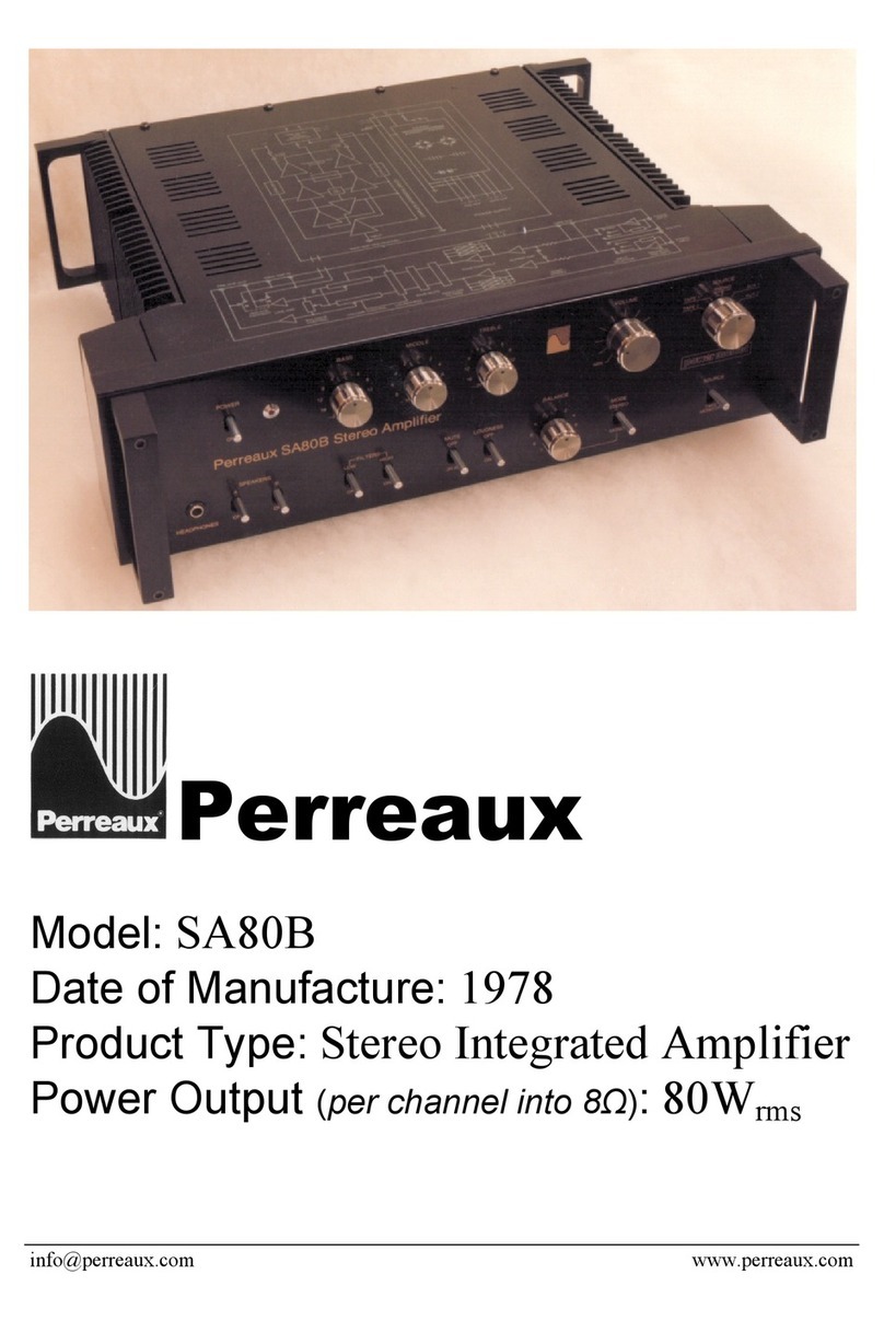
Perreaux SA80B User manual

Perreaux

Perreaux SA80B User manual

Perreaux SX25 User manual

Perreaux

Perreaux SX25 User manual

Perreaux 200iX User manual

Perreaux

Perreaux 200iX User manual

Perreaux SM6 MKII User manual

Perreaux

Perreaux SM6 MKII User manual

Perreaux Silhouette SXH2 User manual

Perreaux

Perreaux Silhouette SXH2 User manual

Perreaux SXP2 User manual

Perreaux

Perreaux SXP2 User manual

Perreaux 3370 User manual

Perreaux

Perreaux 3370 User manual

Perreaux SM4 User manual

Perreaux

Perreaux SM4 User manual

Perreaux 4004A User manual

Perreaux

Perreaux 4004A User manual

Perreaux 6200B User manual

Perreaux

Perreaux 6200B User manual

Perreaux PERREAUX 350  350 350 User manual

Perreaux

Perreaux PERREAUX 350 350 350 User manual

Perreaux SXP2 User manual

Perreaux

Perreaux SXP2 User manual

Perreaux Prisma 750 User manual

Perreaux

Perreaux Prisma 750 User manual

Perreaux 2370 User manual

Perreaux

Perreaux 2370 User manual

Perreaux 6006 User manual

Perreaux

Perreaux 6006 User manual

Perreaux 3000B User manual

Perreaux

Perreaux 3000B User manual

Perreaux GS2002 User manual

Perreaux

Perreaux GS2002 User manual

Perreaux PMF5550 User manual

Perreaux

Perreaux PMF5550 User manual

Perreaux 1221 Quick start guide

Perreaux

Perreaux 1221 Quick start guide

Perreaux SP100II Quick start guide

Perreaux

Perreaux SP100II Quick start guide

Perreaux APV1P User manual

Perreaux

Perreaux APV1P User manual

Perreaux 200i User manual

Perreaux

Perreaux 200i User manual

Perreaux SP10 User manual

Perreaux

Perreaux SP10 User manual

Popular Amplifier manuals by other brands

lab12 suono owner's manual

lab12

lab12 suono owner's manual

Sound Sation ZEUS II H-QX Series user manual

Sound Sation

Sound Sation ZEUS II H-QX Series user manual

Ten-Tec Titan II 416 manual

Ten-Tec

Ten-Tec Titan II 416 manual

Quartzlock A5-32 User handbook

Quartzlock

Quartzlock A5-32 User handbook

Onkyo A-933 instruction manual

Onkyo

Onkyo A-933 instruction manual

OWI AMP-ER2TR6 user manual

OWI

OWI AMP-ER2TR6 user manual

EarthQuake IQ600 user manual

EarthQuake

EarthQuake IQ600 user manual

Denon PMA-1055R Service manual

Denon

Denon PMA-1055R Service manual

Mesa/Boogie TriAxis owner's manual

Mesa/Boogie

Mesa/Boogie TriAxis owner's manual

Esoteric AZ-1 owner's manual

Esoteric

Esoteric AZ-1 owner's manual

Rotel RA-1060 owner's manual

Rotel

Rotel RA-1060 owner's manual

Millennia HV-3R owner's manual

Millennia

Millennia HV-3R owner's manual

Jas Audio Array 2.1 SE instruction manual

Jas Audio

Jas Audio Array 2.1 SE instruction manual

Philips BGY580 datasheet

Philips

Philips BGY580 datasheet

IMI STI BV instruction manual

IMI

IMI STI BV instruction manual

Eico HF-89 instruction manual

Eico

Eico HF-89 instruction manual

Bryston BHA-1 owner's manual

Bryston

Bryston BHA-1 owner's manual

Avantgarde Acoustic XA Series user manual

Avantgarde Acoustic

Avantgarde Acoustic XA Series user manual

manuals.online logo
manuals.online logoBrands
  • About & Mission
  • Contact us
  • Privacy Policy
  • Terms and Conditions

Copyright 2025 Manuals.Online. All Rights Reserved.