Perun Technologies LARA-100 COMM User manual

PERUN
Technologies
LARA-100 APPLICATION BOARD
USER MANUAL

Power Electronics Research Unified Technologies
www.perun-power.com
1
PERUN Technologies
CONTENTS
1 First things first: LARA-100 platform..................................................................................................... 2
1.1 Why LARA-100?............................................................................................................................. 2
1.2 What is LARA-100?........................................................................................................................ 2
2 LARA 100 application boards ................................................................................................................ 7
2.1 LARA 100 application board APP-ENC_INC_SSI_5V...................................................................... 8
2.2 LARA 100 application board APP-ENC_INC_5V_24V ..................................................................18
2.3 LARA 100 application board –APP UI Board............................................................................... 27
3 Document history................................................................................................................................33

Power Electronics Research Unified Technologies
www.perun-power.com
2
PERUN Technologies
1FIRST THINGS FIRST: LARA-100 PLATFORM
Before we give detailed information about LARA-100 Motherboard, let us make a brief introduction in
LARA-100 system in order to get a bigger scope.
If you have been already familiar with LARA-100 concepts you can skip this first chapter and proceed
to the next.
1.1 WHY LARA-100?
The vision behind LARA-100 is to serve its users as a sort of a LAunch RAmp for Power Electronics
control development, research and education. It emerged as the comprehensive answer to the
permanent need for flexibility and comfortable performance in the PE laboratory.
So, how LARA-100 serves you? Instead of building and maintaining a new test-bench whenever dealing
with new project or application PERUN brings you LARA-100 platform which can be re-configured and
re-used according to your present needs.
Therefore, LARA-100 is designed to solve the following:
1. It replaces standard inflexible laboratory test benches and their exhausting modifications with
the platform which can be configured to cover a variety of applications (motor drives, active
filters, PV converter, FACTS, as well as to support some larger research projects, e.g. micro-grids
and smart grids).
2. LARA-100 interfaces with popular controllers such as Texas Instruments C2000 series following
the simple plug and play principle
3. User’s control algorithm is tested directly from an intuitive software suite called PERUN Power
Desk (PPD) which facilitates:
Embedded oscilloscope function which reduces the need for the external oscilloscope
Supervisory control over the system operation
Tag Explorer with the on-line access (read and write) to all variables and parameters
defined by a user
Signal Analysis Desk which processes and analyzes measured results and
Control Design Desk which helps user to design the new control algorithm or modify the
existing one
1.2 WHAT IS LARA-100?
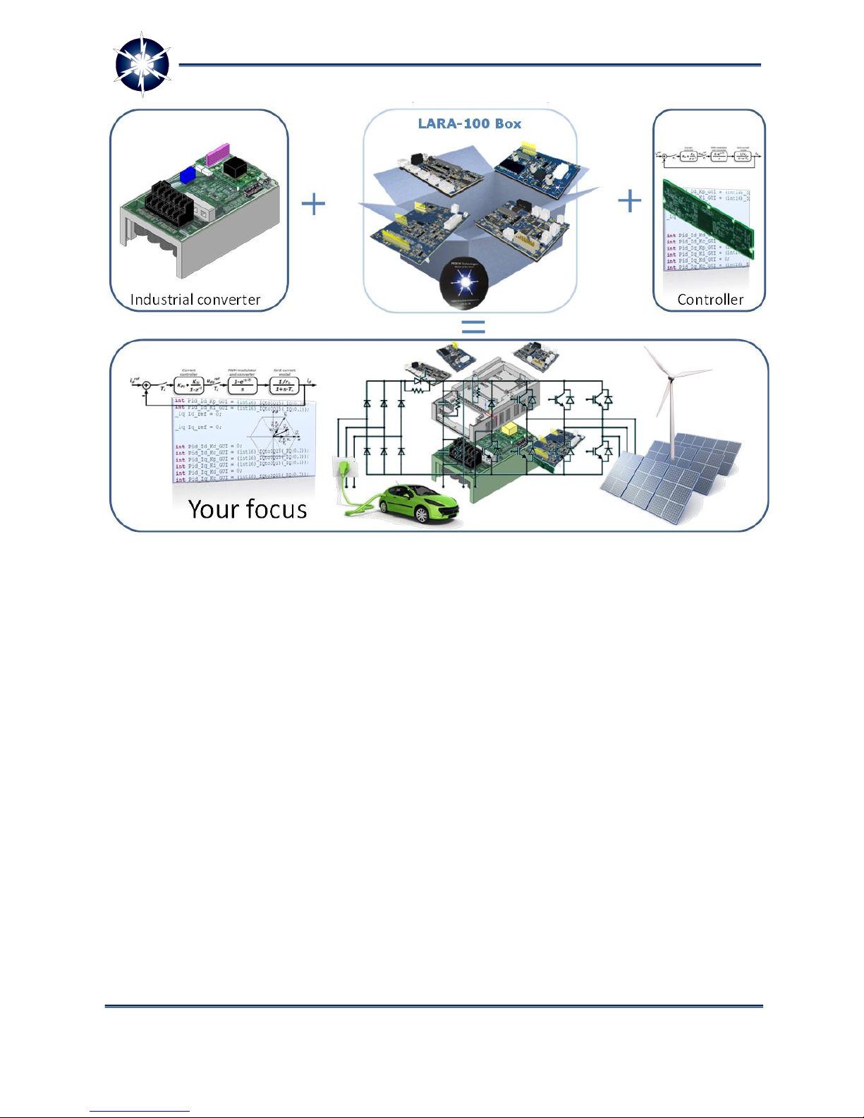
The idea behind LARA-100 is very simple and it can be summarized as follows (Figure 1): let us take
one standard, market available power electronics converter and transform it into the open and re-
configurable platform. How are we supposed to do so?
Power Electronics Research Unified Technologies
www.perun-power.com
3
PERUN Technologies
Figure 1: LARA-100 concept - reconfigurable platform to support applications in your focus
Simply, we will employ the industrial converter's power stage and combine it with LARA's PowerBox
which contains:
LARA's Expansion Boards and
PERUN PowerDesk software suite.
The role of LARA's Expansion Boards together with the PERUN PowerDesk SW is crucial in the concept
of LARA-100 as the open and configurable platform. The role of Expansion Boards is:
interfacing with popular controllers such as Texas Instruments C2000 series
expanding the scope of possible LARA's applications (motor drives, renewables, automotives,
etc)
communication with variety of external devices such as encoders, resolvers, PLCs, other LARAs,
etc. through CAN, USB, Ethernet, JTAG and RS485.
LARA-100 Expansion Boards are:
LARA-100 Motherboard as the main component together with -
Application Boards
Communication and
GPIO Boards.
Power Electronics Research Unified Technologies
www.perun-power.com
4
PERUN Technologies
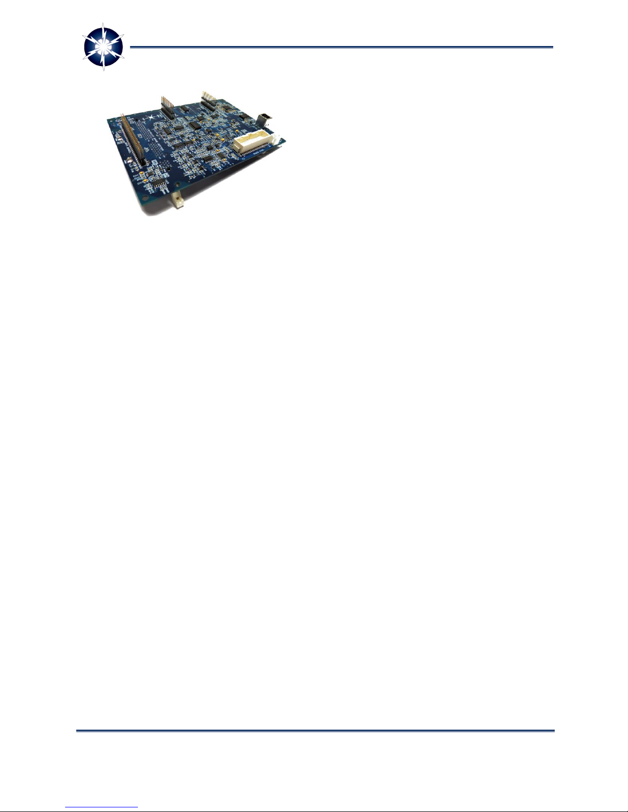
LARA-100 Motherboard has two main functions: the
first one is to enable easy plug-in of controllers (Texas
Instruments C2000 series) and the second one is to
host other Expansion boards based on plug-in
principle. You might think of it in similar way as of PC
motherboard.
The role of LARA-100 Application Boards (APP
Boards) is to extend the LARA-100 system
functionalities and features related to specific power
electronics applications. There are two main types of
Application boards: Motor drive and Grid-Connected.
The first one enables direct interfacing with
incremental/absolute encoders, resolvers or tachogenerators. The second one supports interfaces
with grid voltage lines, photovoltaic (PV) strings, currents measurements, etc. i.e. supports grid-
connected applications.
LARA-100 Communication Boards or simply COMM Boards are compact boards for extension of
LARA-100 system with a variety of standard communication interfaces such as Ethernet, CAN or RS-
485 communication buses. Application note: COMM Boards are ideal solution for expanding LARA-
100 power converters in order to form complex systems such as micro- and smart-grids, where
COMMs are connected with supervisory controllers and several LARAs that stand for different grid
elements.
LARA-100 GPIO (General Purpose Input/Output) comes with all sorts of digital and analog input
and output circuitries. Suitable GPIO Board directly interfaces switches, buttons, power relays,
power contactors, power LEDs, meters, or industrial PLCs with LARA-100 system controller and
quickly build power electronics hardware platform immediately ready for control development and
testing.
LARA's software suite PERUN PowerDesk is responsible for
system configuration
supervisory control
data acquisition
real time access to all controller variables
analysis of measured signals (real time filtering, Fourier)
mathematical manipulations over signals in real time
control design tools (Bode plots, etc.)
Very important fact is that PERUN PowerDesk can be utilized as an integral part of LARA-100 system as
described above, but also it can be employed as a standalone software package. In this scenario a user
can develop and test a control code on Texas Instruments C2000 controller using Perun PowerDesk for
all mentioned purposes except for system configuration (since there is no LARA's hardware). What do
you need in this case? Clearly you need some kind of a docking board to plug in controller and a PC with
installed PERUN PowerDesk. You can use either LARA-100 Motherboard or TI's Experimenter's kit in the
role of the docking board.
Figure 2: LARA-100 Motherboard

Power Electronics Research Unified Technologies
www.perun-power.com
5
PERUN Technologies
Automatic code generation (auto-coding) from Matlab Simulink is supported in PERUN PowerDesk
which makes the process of control design much easier and comfortable. Simply, auto-coding is here to
generate the designed algorithm and PERUN PowerDesk tools proceed with evaluation, testing and re-
design.
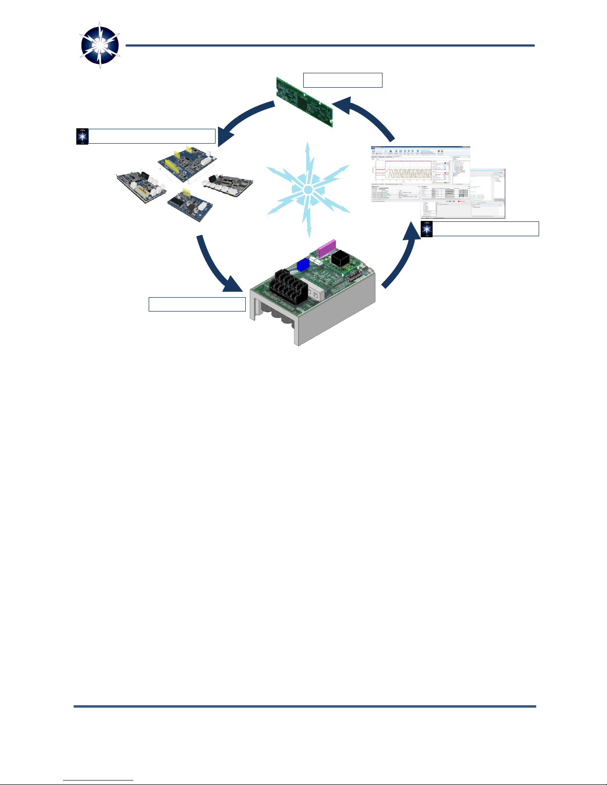
LARA-100 with its HW and SW components presents well rounded and open re-configurable platform
(Figure 3).
Frequently asked questions related to PERUN PowerDesk software suite:
Can I use PERUN PowerDesk without LARA-100 hardware?
The answer is yes. You can use PPD for in a standalone version. In that case you can test and debug
your control code for any kind of application. All you need is Texas Instruments C2000 DSP, a PC with
installed PERUN PowerDesk, a docking board for DSP such as TI’s Experimenter Kit or LARA’s
Motherboard
Can I write a control code directly from PERUN PowerDesk?
The answer is no. The writing of control code is performed with the tool which provides controller
manufacturer, for instance Code Composer Studio if you use Texas Instruments Controller. The role of
PERUN PowerDesk is to assist you in Comfortable higher level debugging and testing through Tag
Explorer, Oscilloscope function and real time signal manipulations and analysis.
What is the difference between PPD Standalone and version which comes with LARA-100?
Both versions have the same key features (PERUN Tag Explorer, Oscilloscope and Signal Analysis Desk.
The version which comes with LARA has a link to LARA HW and therefore enables supervisory control
of LARA configured in one of required Power Electronics applications
Power Electronics Research Unified Technologies
www.perun-power.com
6
PERUN Technologies
Figure 3: LARA-100 main components
In the continuation of this document the focus is set to LARA-100 Application Boards.
Industrial Converter
PERUN’s Expansion Boards
User’s controller
PERUN PowerDesk SW
LARA-100
Power Electronics Research Unified Technologies
www.perun-power.com
7
PERUN Technologies
2LARA 100 APPLICATION BOARDS
LARA-100 APPs (application) are compact boards for extension of LARA-100 system functionalities and
features related to specific power electronics applications. Motherboard can be connected with various
APP Boards that come with all sorts of interfaces. User can quickly build specific power electronics
hardware platform immediately ready for control development and testing. By using suitable APP Board
user can directly interface incremental/absolute encoders, resolvers or tachogenerators if you are
considering motor drive, or grid voltage lines and photovoltaic (PV) strings if you are considering grid-
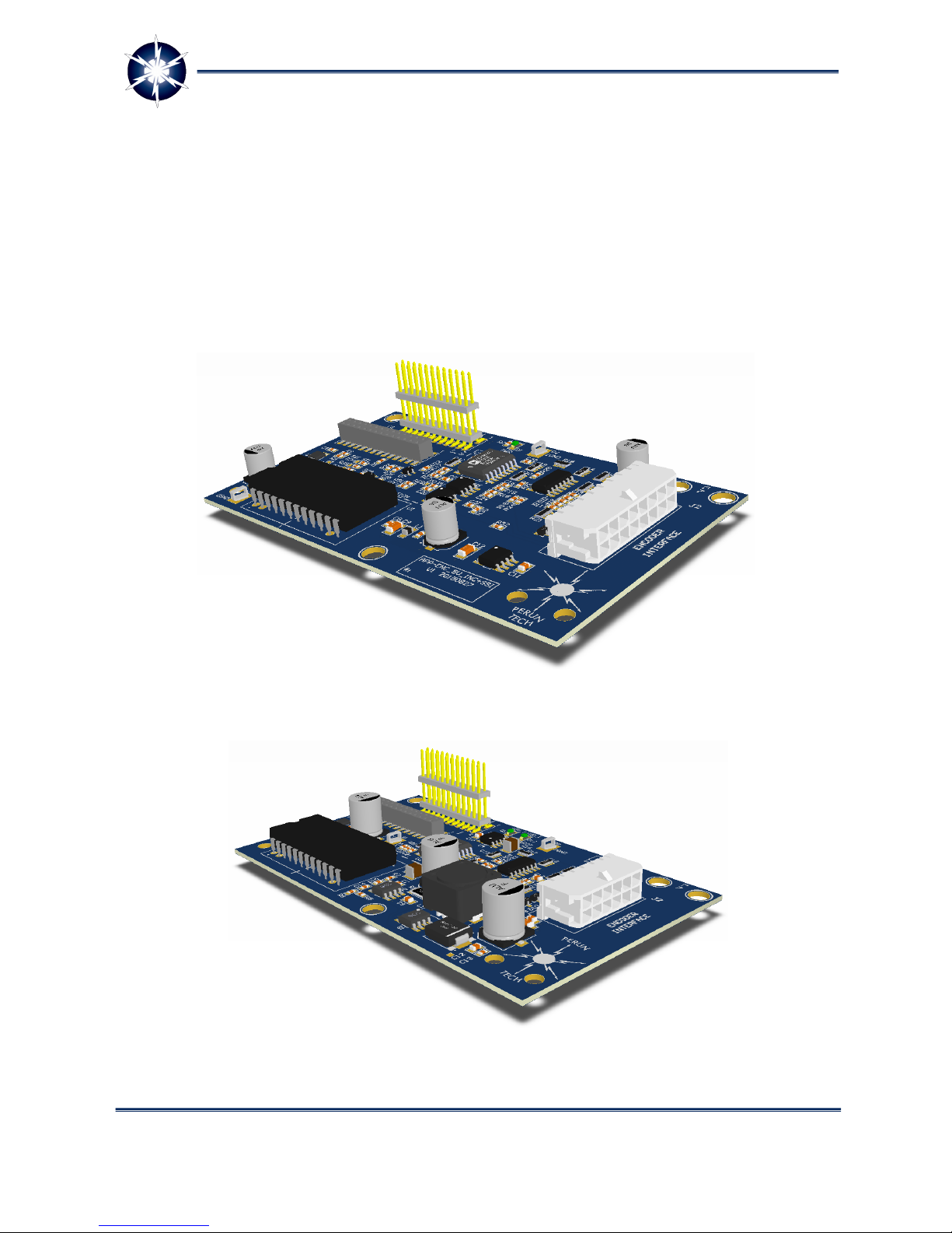
connected application. On the following figures you can see three types of APP boards.
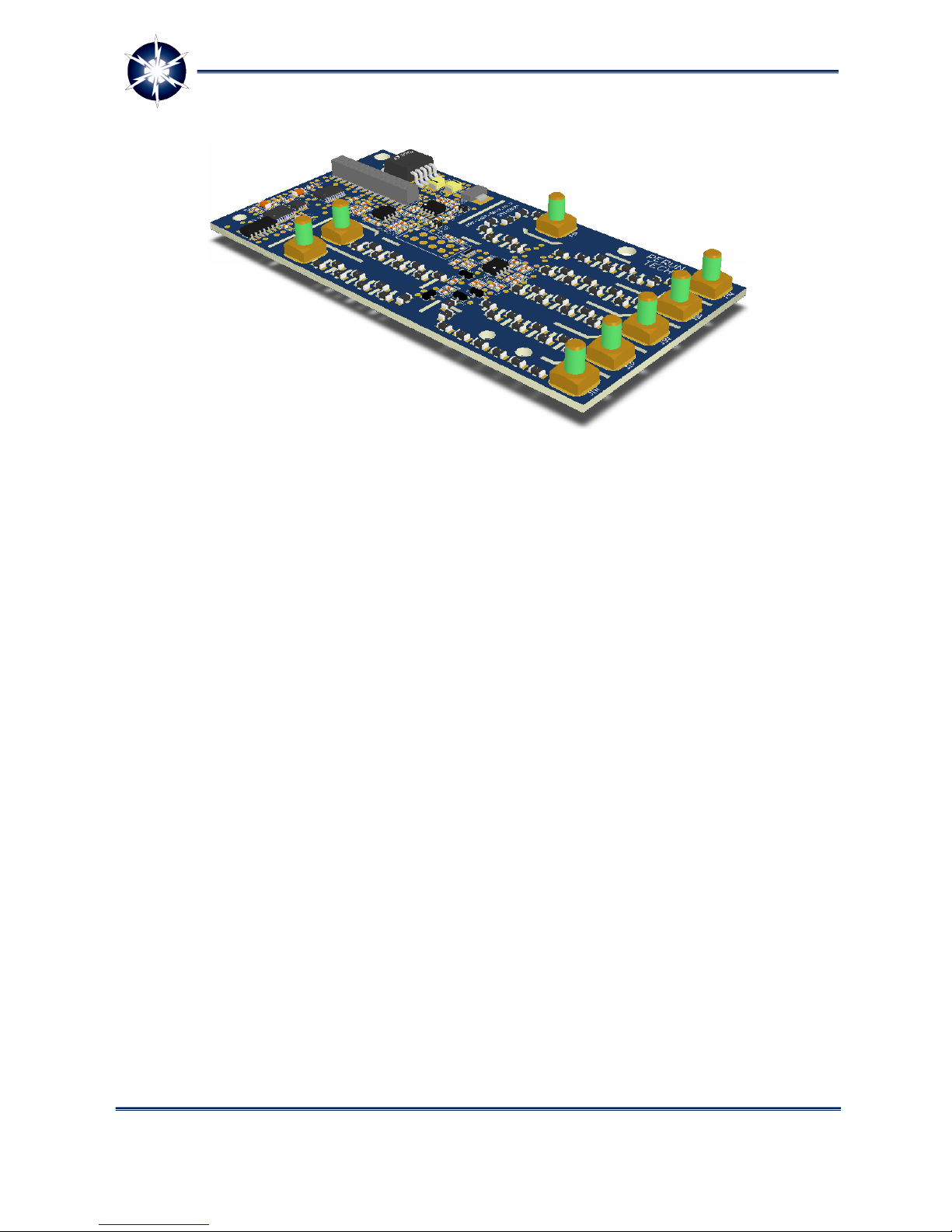
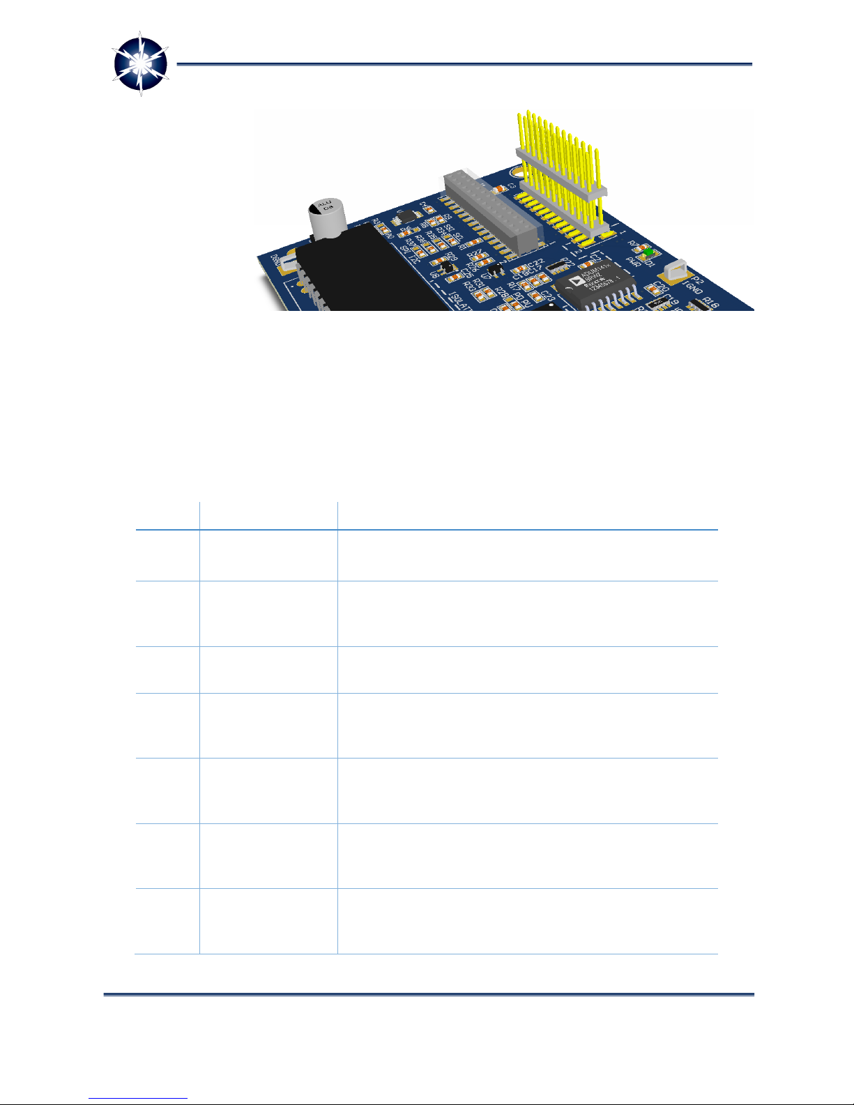
Figure 4: LARA 100 application board APP-ENC_INC_SSI_5V
Figure 5: LARA 100 application board APP-ENC_INC_5V_24V
Power Electronics Research Unified Technologies
www.perun-power.com
8
PERUN Technologies
Figure 6: LARA 100 application board APP-UI
2.1 LARA 100 APPLICATION BOARD APP-ENC_INC_SSI_5V
APP-ENC_INC_SSI_5V Board (Figure 4) allows interfacing of widely used industrial incremental and
absolute rotary encoders with SSI interface (Synchronous Serial Interface) for receiving rotor position
data in motor drives. It provides isolated interface between Controller Board’s quadrature encoder
peripheral inputs (QEP) and incremental encoders with quadrature differential signals A, B, I, /A, /B, and
/I. Additionally, it supports isolated point to point connection between master Controller Board and
slave absolute encoders with SSI interface. On Controller Board side SSI is implemented using SPI
peripheral, or optionally with general purpose inputs/outputs. The board is designed to use 5 V
encoders. Figure 7 shows connectors displacement and its explanation.
Power Electronics Research Unified Technologies
www.perun-power.com
9
PERUN Technologies
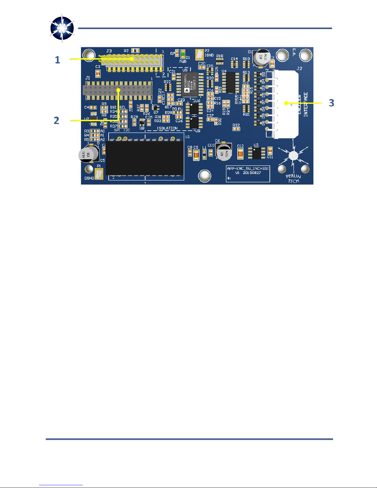
Figure 7: APP-ENC_INC_SSI_5V connectors
Connectors have the following meaning:
1 –APP-ADD Board interface (J3) –It provides extension of functionalities of your APP Board through
connection of additional application APP-ADD Board. User can connect another encoder, tacho speed
sensor, limit switches or measure high-voltages or currents.
2 –APP Board interface (J1) –It provides connection with Motherboard in order to directly interface
its controller and incremental quadrature and/or absolute rotary encoders, using controller’s QEP and
SPI peripherals.
3 –Encoder interface (J2) –It provides connection of incremental and/or absolute rotary encoders
with +5 V interface. It accepts differential quadrature signals A, B, /A, B/, index signals I, /I, and strobe
signals S, /S, and SSI bus signals (clock CLK, data output DO, data input DI, and chip select CS).
APP-ENC_INC_SSI_5V Board is plug-and-play solution for LARA-100 Motherboard ideal for receiving
incremental and absolute rotary encoder’s position data in LARA-100 Motor Drive system. The board
features three connectors: for connecting an external encoder, for connecting to LARA-100
Motherboard and additional application board APP-ADD for further expansion. Following figure gives
an overview of connection between the controller and encoder.
Power Electronics Research Unified Technologies
www.perun-power.com
10
PERUN Technologies
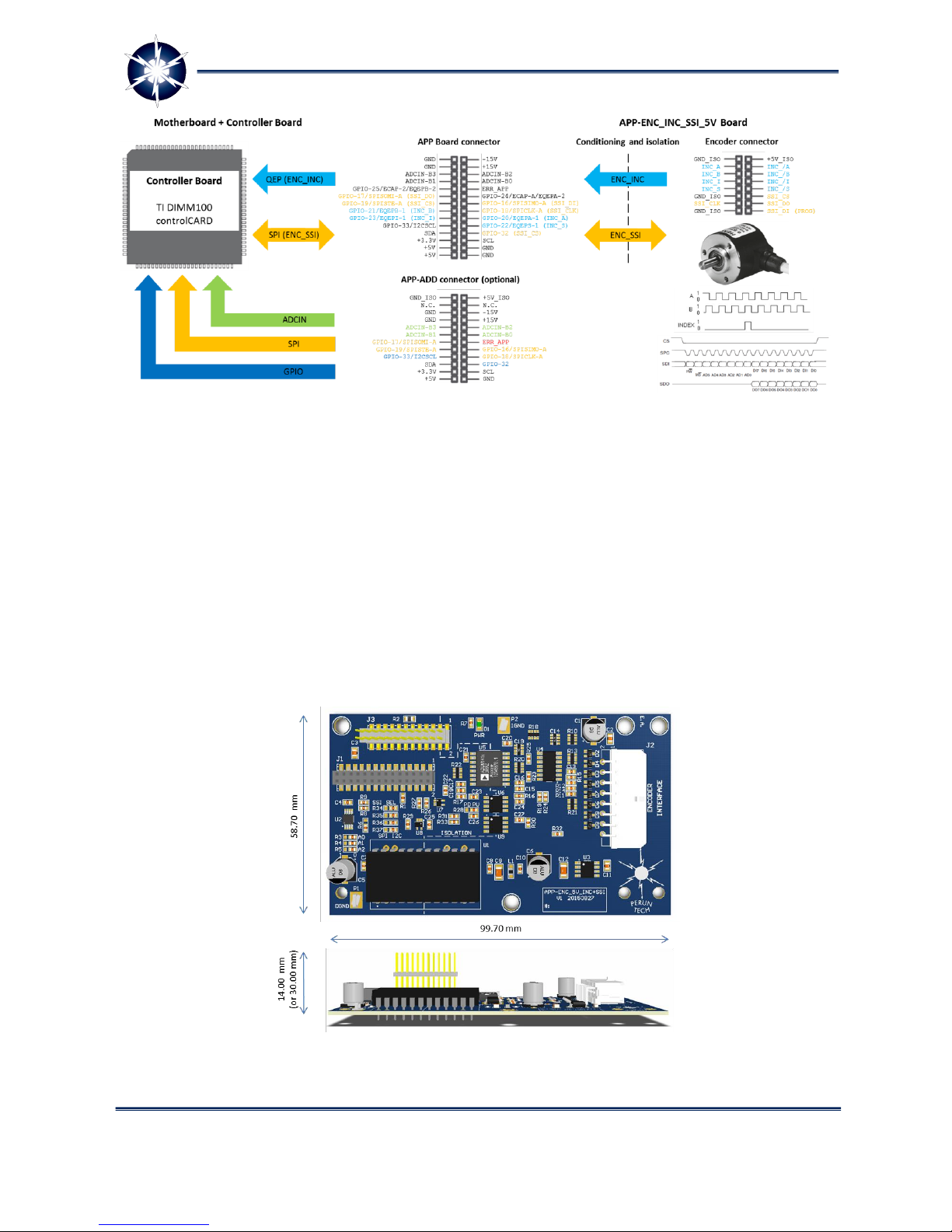
Figure 8: Overview of connection between controller and encoder - by using APP-
ENC_INC_SSI_5V
Technical specification for APP-ENC_INC_SSI_5V board
APP-ENC_INC_SSI_5V board dimensions, fixture holes and connector position are carefully designed in
order to fit into the original cover box of the industrial power converter. User should plug APP Board to
previously mounted LARA-100 Motherboard, fix it to the Power Stage cover box and controller is ready
to communicate with standard industrial incremental and absolute rotary encoders. In this way,
complete LARA-100 Motor Drive system have compact external layout as industrial drives, which is not
usual case with open development platforms.
Figure 9: APP-ENC_INC_SSI_5V board dimensions
Power Electronics Research Unified Technologies
www.perun-power.com
11
PERUN Technologies
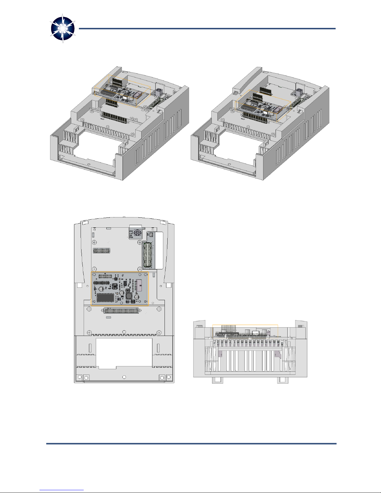
Following figures represent process of mounting of APP-ENC_INC_SSI_5V board on the industrial
power stage (only mechanical cover is shown).
Figure 10: Power Stage cover box with LARA-100 Motherboard and APP-ENC_INC_SSI_5V
Board aligned for mounting (left fig.). APP-ENC_INC_SSI_5V Board mounted on LARA-100
Motherboard and Power Stage cover box (right fig.).
Figure 11: APP-ENC_INC_SSI_5V board mounted on LARA-100 Motherboard and Power
Stage cover box –look from top (left fig.). APP-ENC_INC_SSI_5V Board mounted on LARA-
100 Motherboard and Power Stage cover box –look from front (right fig.)
Power Electronics Research Unified Technologies
www.perun-power.com
12
PERUN Technologies
APP-ENC_INC_SSI_5V
board has SAMTEC
MMS-114-02-F-DV
28-pin female
connector (2.00 mm
Tiger Claw Socket
Strip, double row, 14-
pins per row) for
direct use with LARA-
100 Motherboard. It
fits to
Motherboard’s
SAMTEC TW-14-07-F-D-350-SM-000 Application Board connector and allow simple plug-and-play
concept for extending Motherboard functionalities.
Pin assignments of Application Board connector on APP-ENC_INC_SSI_5V board, related to the
Controller Board (TI DIMM100 control Cards) is given in following table:
Table 1: Pin assignment of application board connector J1
Pin
Signal
Description
1
GND
Ground reference for Application Board power supply
(+3.3V, +5V, -15V, and +15V).
2
-15V
-15 V power supply on Application Board. Not used on
APP-ENC_INC_SSI_5V board. Provided to J3 APP-ADD
connector.
3
GND
Ground reference for Application Board power supply
(+3.3V, +5V, -15V, and +15V).
4
+15V
+15 V power supply on Application Board. Not used on
APP-ENC_INC_SSI_5V board. Provided to J3 APP-ADD
connector.
5
ADCIN-B3
Pin directly connected to Controller Board analog input
ADCIN-B3. Not used on APP-ENC_INC_SSI_5V board.
Provided to J3 APP-ADD connector.
6
ADCIN-B2
Pin directly connected to Controller Board analog input
ADCIN-B2. Not used on APP-ENC_INC_SSI_5V board.
Provided to J3 APP-ADD connector.
7
ADCIN-B1
Pin directly connected to Controller Board analog input
ADCIN-B1. Not used on APP-ENC_INC_SSI_5V board.
Provided to J3 APP-ADD connector.
Figure 12: Application Board connector (J1) –PCB overview

Power Electronics Research Unified Technologies
www.perun-power.com
13
PERUN Technologies
Pin
Signal
Description
8
ADCIN-B0
Pin directly connected to Controller Board analog input
ADCIN-B0. Not used on APP-ENC_INC_SSI_5V board.
Provided to J3 APP-ADD connector.
9
GPIO-25/ECAP-
2/EQEPB-2
Pin directly connected to Controller Board general purpose
input/output GPIO-25. Not used on APP-ENC_INC_SSI_5V
board. Provided to J3 APP-ADD connector.
10
ERR_APP
Protection digital input dedicated for direct setting LARA-
100 system in error state through Application Board. Low
signal (0 V) on this pin will immediately activate
Motherboard error signal and disable all PWM signals. Not
used on APP-ENC_INC_SSI_5V board. Provided to J3 APP-
ADD connector.
11
GPIO-17/SPISOMI-A
Pin directly connected to Controller Board general purpose
input/output GPIO-17. This pin function as SPI bus
SOMI/MISO pin for communication with absolute rotary
encoder (with SSI interface) connected on J2 connector.
12
GPIO-24/ECAP-
1/EQEPA-2
Pin directly connected to Controller Board general purpose
input/output GPIO-24. Not used on APP-ENC_INC_SSI_5V
board. Provided to J3 APP-ADD connector.
13
GPIO-19/SPISTE-A
Pin directly connected to Controller Board general purpose
input/output GPIO-19. This pin function as SPI bus select
pin for communication with absolute rotary encoder (with
SSI interface) connected on J2 connector.
14
GPIO-16/SPISIMO-A
Pin directly connected to Controller Board general purpose
input/output GPIO-16. This pin function as SPI bus
SIMO/MOSI pin for communication with absolute rotary
encoder (with SSI interface) connected on J2 connector.
15
GPIO-21/EQEPB-1
Pin directly connected to Controller Board general purpose
input/output GPIO-21. This pin function as quadrature
encoder input B (QEPB) for interfacing with incremental
encoder connected on J2 connector.
16
GPIO-18/SPICLK-A
Pin directly connected to Controller Board general purpose
input/output GPIO-18. This pin function as SPI bus CLK pin
for communication with absolute rotary encoder (with SSI
interface) connected on J2 connector.
17
GPIO-23/EQEPI-1
Pin directly connected to Controller Board general purpose
input/output GPIO-23. This pin function as encoder index
input I (QEPI) for interfacing with incremental encoder
connected on J2 connector.

Power Electronics Research Unified Technologies
www.perun-power.com
14
PERUN Technologies
Pin
Signal
Description
18
GPIO-20/EQEPA1
Pin directly connected to Controller Board general purpose
input/output GPIO-20. This pin function as quadrature
encoder input A (QEPA) for interfacing with incremental
encoder connected on J2 connector.
19
GPIO-33/I2CSCL
Pin directly connected to Controller Board general purpose
input/output GPIO-33. Not used on APP-ENC_INC_SSI_5V
board. Provided to J3 APP-ADD connector.
20
GPIO-22/EQEPS-1
Pin directly connected to Controller Board general purpose
input/output GPIO-22. This pin function as encoder strobe
input S (QEPS) for interfacing with incremental encoder
connected on J2 connector.
21
SDA
Pin reserved for communication link with PERUN
PowerDesk software through Motherboard USB
connection.
22
GPIO-32
Pin directly connected to Controller Board general purpose
input/output GPIO-32. This pin function as SPI bus select
pin for communication with absolute rotary encoder (with
SSI interface) connected on J2 connector. Together with
GPIO-19/SPISTE-A generates SSI select signal for encoder.
23
+3.3V
+3.3V power supply for digital circuits on Application
Board.
24
SCL
Pin reserved for communication link with PERUN
PowerDesk software through Motherboard USB
connection.
25
+5V
+5V power supply for digital circuits on Application Board.
26
GND
Ground reference for Application Board power supply
(+3.3V, +5V, -15V, and +15V).
27
+5V
+5V power supply for digital circuits on Application Board.
28
GND
Ground reference for Application Board power supply
(+3.3V, +5V, -15V, and +15V).
Application (APP) Board connector (J1) is shown in the figure below.

Power Electronics Research Unified Technologies
www.perun-power.com
15
PERUN Technologies
Figure 13: Application board connector J1
APP-ENC_INC_SSI_5V board has MOLEX Micro-Fit
3.0 0430451600 16-pin connector (3.00 mm pitch,
male pin, double row, right angle, shrouded
header with locking ramp) for connection of
rotary encoders. Use matching MOLEX Micro-Fit
3.0 receptacle female socket 0430251600 with
0430300001 crimp contacts to wire (20-24 AWG)
external encoders to the board.
Pin assignments of Encoder connector related to an external encoders and Motherboard and
Controller Board (TI DIMM100 control Cards) is given in following table.
Table 2: Pin assignment of encoder connector J2
Pin
Signal
Description
1
GND_ISO
Ground reference for external encoder. This ground is
isolated from Motherboard’s and Controller Board’s ground
signal (GND).
2
+5V_ISO
Isolated +5 V power supply for external encoder.
3
INC_A / GPIO-20 /
EQEPA-1
Incremental encoder input for quadrature impulse A.
Differential inputs A and /A are isolated and conditioned to
Figure 14: Encoder connector J2

Power Electronics Research Unified Technologies
www.perun-power.com
16
PERUN Technologies
Pin
Signal
Description
3,3 V level for Controller Board’s QEP (Quadrature Encoder
Peripheral) input EQEPA-1 (GPIO-20).
4
INC_/A / GPIO-20 /
EQEPA-1
Incremental encoder input for inverted quadrature impulse
/A. Differential inputs A and /A are isolated and
conditioned to 3,3 V level for Controller Board’s QEP
(Quadrature Encoder Peripheral) input EQEPA-1 (GPIO-20).
5
INC_B / GPIO-21 /
EQEPB-1
Incremental encoder input for quadrature impulse B.
Differential inputs B and /B are isolated and conditioned to
3,3 V level for Controller Board’s QEP (Quadrature Encoder
Peripheral) input EQEPB-1 (GPIO-21).
6
INC_/B / GPIO-21 /
EQEPB-1
Incremental encoder input for inverted quadrature impulse
B. Differential inputs B and /B are isolated and conditioned
to 3,3 V level for Controller Board’s QEP (Quadrature
Encoder Peripheral) input EQEPB-1 (GPIO-21).
7
INC_I / GPIO-23 /
EQEPI-1
Incremental encoder input for index impulse I. Differential
inputs I and /I are isolated and conditioned to 3,3 V level
for Controller Board’s QEP (Quadrature Encoder Peripheral)
index input EQEPI-1 (GPIO-23).
8
INC_/I / GPIO-23 /
EQEPI-1
Incremental encoder input for inverted index impulse I.
Differential inputs I and /I are isolated and conditioned to
3,3 V level for Controller Board’s QEP (Quadrature Encoder
Peripheral) index input EQEPI-1 (GPIO-23).
9
INC_S / GPIO-22 /
EQEPS-1
Incremental encoder input for strobe impulse S.
Differential inputs S and /S are isolated and conditioned to
3,3 V level for Controller Board’s QEP (Quadrature Encoder
Peripheral) strobe input EQEPS-1 (GPIO-22).
10
INC_/S / GPIO-22 /
EQEPS-1
Incremental encoder input for inverted strobe impulse S.
Differential inputs S and /S are isolated and conditioned to
3,3 V level for Controller Board’s QEP (Quadrature Encoder
Peripheral) strobe input EQEPS-1 (GPIO-22).
11
GND_ISO
Ground reference for external encoder. This ground is
isolated from Motherboard’s and Controller Board’s ground
signal (GND).
12
SSI_CS / GPIO-32 +
GPIO-19/SPISTE-A
SSI interface chip select signal (CS) for external absolute
encoder. Controller Board’s GPIO-32 and SPISTE-A (GPIO-
19) signals, together, generates chip select signal which is
isolated and conditioned to 5 V level for external encoder.
13
SSI_CLK / GPIO-
18/SPICLK-A
SSI interface clock signal (CLK) for external absolute
encoder. Controller Board’s SPICLK-A (GPIO-18) clock signal
is isolated and conditioned to 5 V level for external

Power Electronics Research Unified Technologies
www.perun-power.com
17
PERUN Technologies
Pin
Signal
Description
encoder.
14
SSI_DO / GPIO-
17/SPISOMI-A
SSI interface data output signal (DO) for external absolute
encoder. On this pin, APP board (master) receives data
from encoder (slave). Encoder signal SSI_DO (5 V level) is
isolated and conditioned to 3,3 V level for Controller
Board’s SPISOMI-A (GPIO-17) input.
15
GND_ISO
Ground reference for external encoder.
16
SSI_DI / GPIO-
16/SPISIMO-A
SSI interface data input signal (DO) for external absolute
encoder with built-in SSI. On this pin, APP board (master)
transmits data to encoder (slave). This line is used with
encoders which can be programmed/configured. Controller
Board’s SPISIMO-A (GPIO-16) data signal is isolated and
conditioned to 5 V level for external encoder.
Following figure represent J2 encoder connector pin assignment.
Figure 15: Encoder connector J2 and pin assignment

Power Electronics Research Unified Technologies
www.perun-power.com
18
PERUN Technologies
2.2 LARA 100 APPLICATION BOARD APP-ENC_INC_5V_24V
APP-ENC_INC_5V_24V Board (Figure 5) allows interfacing of widely used industrial incremental
encoders for rotor position feedback in motor drives. It provides isolated interface between Controller
Board’s quadrature encoder peripheral (QEP) and incremental encoders with quadrature differential
signals A, /A, and B, /B, and index signals I, /I. The configurable on-board isolated power supply
supports connection of encoders with different power supply standard voltage levels in the range from
5 V to 24 V (5, 9, 12, 15 and 24 V). Figure 16 shows connectors displacement and its explanation.
Figure 16: LARA 100 application board connectors
Connectors have the following meaning:
1 –APP-ADD Board interface (J3) –It extend functionalities of APP Board through connection of
additional application APP-ADD Board. Another encoder, tacho speed sensor, limit switches or measure
high-voltages or currents can be used.
2 –APP Board interface (J1) –It provides connection with Motherboard in order to directly interface
its controller and incremental quadrature rotary encoders, using controller’s QEP peripheral.
3 –Encoder interface (J2) –It provides connection of incremental rotary encoders with +5 V to +24 V
interface. It accepts differential quadrature signals A, B, /A, B/, index signals I, /I, and strobe signals S,
/S.

Power Electronics Research Unified Technologies
www.perun-power.com
19
PERUN Technologies
APP-ENC_INC_5V_24V Board is plug-and-play solution for LARA-100 Motherboard ideal for interfacing
incremental rotary encoders in LARA-100 Motor Drive systems. The board features three connectors: for
connecting an external incremental encoder, for connecting to LARA-100 Motherboard and additional
application board APP-ADD for further expansion. Following figure gives an overview of connection
between the controller and encoder.
Figure 17: Overview of connection between controller and encoder - by using APP-
ENC_INC_5V_24V
Technical specification for APP-ENC_INC_5V_24V board
APP-ENC_INC_5V_24V board dimensions, fixture holes and connector position are carefully designed in
order to fit into the original cover box of the industrial power converter. User can plug APP Board to
previously mounted LARA-100 Motherboard, fix it to the Power Stage cover box and controller is ready
to communicate with standard industrial incremental quadrature encoders. In this way, complete LARA-
100 Motor Drive system have compact external layout as industrial drives, which is not usual case with
open development platforms.
Other manuals for LARA-100 COMM
2
Table of contents
Other Perun Technologies Motherboard manuals


