Perun Technologies LARA-100 COMM User manual

PERUN
Technologies
LARA-100 MOTHERBOARD
USER MANUAL

Power Electronics Research Unified Technologies
www.perun-power.com
1
PERUN Technologies
CONTENTS
1 First things first: LARA-100 platform..................................................................................................... 2
1.1 Why LARA-100?............................................................................................................................. 2
1.2 What is LARA-100?........................................................................................................................ 2
2 LARA 100 MOTHERBOARD .................................................................................................................... 7
3 Technical data ..................................................................................................................................... 39
3.1 PWM outputs circuit ...................................................................................................................42
3.2 Protection logic –error signal generation circuit........................................................................ 43
3.3 Overcurrent protection circuit ....................................................................................................47
3.4 DC-link under/overvoltage protection circuit ............................................................................. 49
3.5 Manual error trigger circuit......................................................................................................... 51
3.6 Error signal reset circuit ..............................................................................................................52
3.7 PWM pulses enable circuit.......................................................................................................... 53
3.8 Current measurement circuit...................................................................................................... 54
3.9 DC-link voltage measurement circuit.......................................................................................... 56
3.10 Pre-charge thyristor and braking chopper turn on/off circuit .................................................... 58
3.11 Communication circuits ..............................................................................................................60
3.12 Power Supply circuits ..................................................................................................................63
4 Connection examples..........................................................................................................................65
5 Document history................................................................................................................................ 68

Power Electronics Research Unified Technologies
www.perun-power.com
2
PERUN Technologies
1FIRST THINGS FIRST: LARA-100 PLATFORM
Before we give detailed information about LARA-100 Motherboard, let us make a brief introduction in
LARA-100 system in order to get a bigger scope.
If you have been already familiar with LARA-100 concepts you can skip this first chapter and go
immediately to the second.
1.1 WHY LARA-100?
The vision behind LARA-100 is to serve its users as a sort of a LAunch RAmp for Power Electronics
control development, research and education. It emerged as the comprehensive answer to the
permanent need for flexibility and comfortable performance in the PE laboratory.
So, how LARA-100 serves you? Instead of building and maintaining a new test-bench whenever dealing
with new project or application PERUN brings you LARA-100 platform which can be re-configured and
re-used according to your present needs.
Therefore, LARA-100 is designed to solve the following:
1. It replaces standard inflexible laboratory test benches and their exhausting modifications with
the platform which can be configured to cover a variety of applications (motor drives, active
filters, PV converter, FACTS, as well as to support some larger research projects, e.g. micro-grids
and smart grids).
2. LARA-100 interfaces with popular controllers such as Texas Instruments C2000 series following
the simple plug and play principle
3. User’s control algorithm is tested directly from an intuitive software suite called PERUN Power
Desk (PPD) which facilitates:
Embedded oscilloscope function which reduces the need for the external oscilloscope
Supervisory control over the system operation
Tag Explorer with the on-line access (read and write) to all variables and parameters
defined by a user
Signal Analysis Desk which processes and analyzes measured results and
Control Design Desk which helps user to design the new control algorithm or modify the
existing one
1.2 WHAT IS LARA-100?
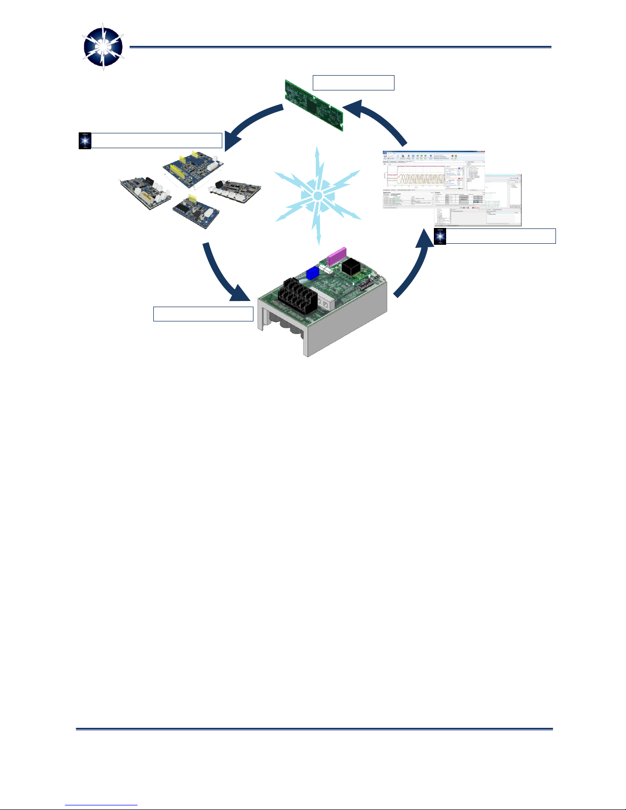
The idea behind LARA-100 is very simple and it can be summarized as follows (Figure 1): let us take
one standard, market available power electronics converter and transform it into the open and re-
configurable platform. How are we supposed to do so?

Power Electronics Research Unified Technologies
www.perun-power.com
3
PERUN Technologies
Figure 1: LARA-100 concept - reconfigurable platform to support applications in your focus
Simply, we will employ the industrial converter's power stage and combine it with LARA's PowerBox
which contains:
LARA's Expansion Boards and
PERUN PowerDesk software suite.
The role of LARA's Expansion Boards together with the PERUN PowerDesk SW is crucial in the concept
of LARA-100 as the open and configurable platform. The role of Expansion Boards is:
interfacing with popular controllers such as Texas Instruments C2000 series
expanding the scope of possible LARA's applications (motor drives, renewables, automotives,
etc.)
communication with variety of external devices such as encoders, resolvers, PLCs, other LARAs,
etc. through CAN, USB, Ethernet, JTAG and RS485.
LARA-100 Expansion Boards are:
LARA-100 Motherboard as the main component together with -
Application Boards
Communication and
GPIO Boards.

Power Electronics Research Unified Technologies
www.perun-power.com
4
PERUN Technologies
LARA-100 Motherboard has two main functions: the
first one is to enable easy plug-in of controllers (Texas
Instruments C2000 series) and the second one is to
host other Expansion boards based on plug-in
principle. You might think of it in similar way as of PC
motherboard.
The role of LARA-100 Application Boards (APP
Boards) is to extend the LARA-100 system
functionalities and features related to specific power
electronics applications. There are two main types of
Application boards: Motor drive and Grid-Connected.
The first one enables direct interfacing with
incremental/absolute encoders, resolvers or tachogenerators. The second one supports interfaces
with grid voltage lines, photovoltaic (PV) strings, currents measurements, etc. i.e. supports grid-
connected applications.
LARA-100 Communication Boards or simply COMM Boards are compact boards for extension of
LARA-100 system with a variety of standard communication interfaces such as Ethernet, CAN or RS-
485 communication buses. Application note: COMM Boards are ideal solution for expanding LARA-
100 power converters in order to form complex systems such as micro- and smart-grids, where
COMMs are connected with supervisory controllers and several LARAs that stand for different grid
elements.
LARA-100 GPIO (General Purpose Input/Output) comes with all sorts of digital and analog input
and output circuitries. Suitable GPIO Board directly interfaces switches, buttons, power relays,
power contactors, power LEDs, meters, or industrial PLCs with LARA-100 system controller and
quickly build power electronics hardware platform immediately ready for control development and
testing.
LARA's software suite PERUN PowerDesk is responsible for
system configuration
supervisory control
data acquisition
real time access to all controller variables
analysis of measured signals (real time filtering, Fourier)
mathematical manipulations over signals in real time
control design tools (Bode plots, etc.)
Very important fact is that PERUN PowerDesk can be utilized as an integral part of LARA-100 system as
described above, but also it can be employed as a standalone software package. In this scenario a user
can develop and test a control code on Texas Instruments C2000 controller using Perun PowerDesk for
all mentioned purposes except for system configuration (since there is no LARA's hardware). What do
you need in this case? Clearly you need some kind of a docking board to plug in controller and a PC with
installed PERUN PowerDesk. You can use either LARA-100 Motherboard or TI's Experimenter's kit in the
role of the docking board.
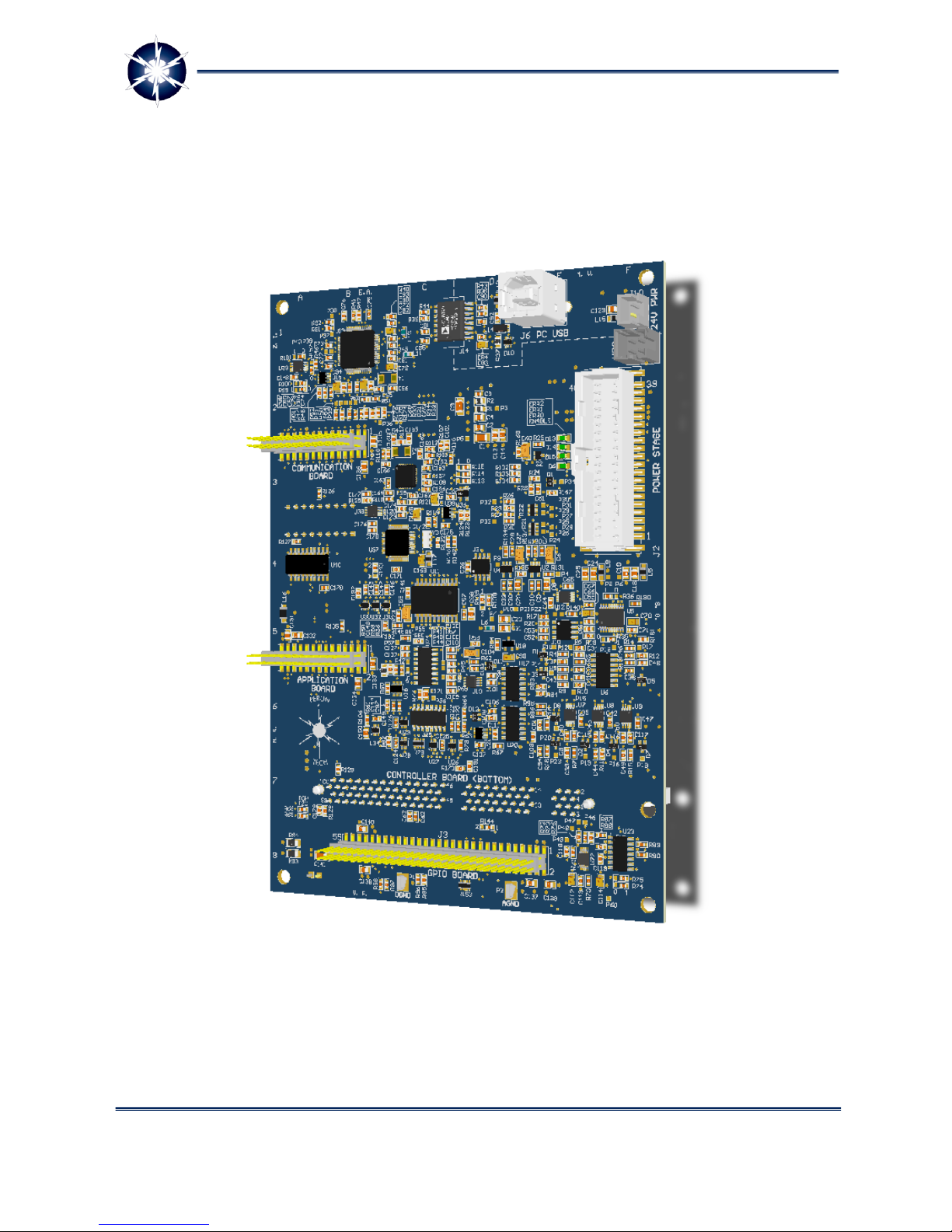
Figure 2: LARA-100 Motherboard

Power Electronics Research Unified Technologies
www.perun-power.com
5
PERUN Technologies
Automatic code generation (auto-coding) from Matlab Simulink is supported in PERUN PowerDesk
which makes the process of control design much easier and comfortable. Simply, auto-coding is here to
generate the designed algorithm and PERUN PowerDesk tools proceed with evaluation, testing and re-
design.
LARA-100 with its HW and SW components presents well rounded and open re-configurable platform
(Figure 3).
Frequently asked questions related to PERUN PowerDesk software suite:
Can I use PERUN PowerDesk without LARA-100 hardware?
The answer is yes. You can use PPD for in a standalone version. In that case you can test and debug
your control code for any kind of application. All you need is Texas Instruments C2000 DSP, a PC with
installed PERUN PowerDesk, a docking board for DSP such as TI’s Experimenter Kit or LARA’s
Motherboard
Can I write a control code directly from PERUN PowerDesk?
The answer is no. The writing of control code is performed with the tool which provides controller
manufacturer, for instance Code Composer Studio if you use Texas Instruments Controller. The role of
PERUN PowerDesk is to assist you in Comfortable higher level debugging and testing through Tag
Explorer, Oscilloscope function and real time signal manipulations and analysis.
What is the difference between PPD Standalone and version which comes with LARA-100?
Both versions have the same key features (PERUN Tag Explorer, Oscilloscope and Signal Analysis Desk.
The version which comes with LARA has a link to LARA HW and therefore enables supervisory control
of LARA configured in one of required Power Electronics applications
Power Electronics Research Unified Technologies
www.perun-power.com
6
PERUN Technologies
Figure 3: LARA-100 main components
In the continuation of this document the focus is set to LARA-100 Motherboard.
Industrial Converter
PERUN’s Expansion Boards
User’s controller
PERUN PowerDesk SW
LARA-100
Power Electronics Research Unified Technologies
www.perun-power.com
7
PERUN Technologies
2LARA 100 MOTHERBOARD
LARA-100 MOTHERBOARD is a main board interfacing power electronics stage (Power Stage) and its
controller (Controller Board). Making and putting together fully-functional power electronics devices
opened for control development and testing, have never been easier!
Figure 4: LARA 100 Motherboard
Figure 5 and Figure 6 gives overview of external connection interfaces.

Power Electronics Research Unified Technologies
www.perun-power.com
8
PERUN Technologies
Figure 5: LARA 100 Motherboard connectors –upper side

Power Electronics Research Unified Technologies
www.perun-power.com
9
PERUN Technologies
Figure 6: LARA 100 Motherboard connectors –bottom side
Connectors have the following meaning:
1 –Communication Board interface –Connect supervisory and power stage controller over different
communication buses, such as RS-232, RS-485, CAN or Ethernet, with just plugging suitable PERUN’s
Communication Board.
2 –Application Board interface –Adapt the LARA-100 system to the specific power electronics
application, using one of the PERUN’s Application Boards. Go ahead and work with motor drives, grid-
connected converters or solar boost converters right away.

Power Electronics Research Unified Technologies
www.perun-power.com
10
PERUN Technologies
3 –Controller Board interface (on bottom side) –See note 7.
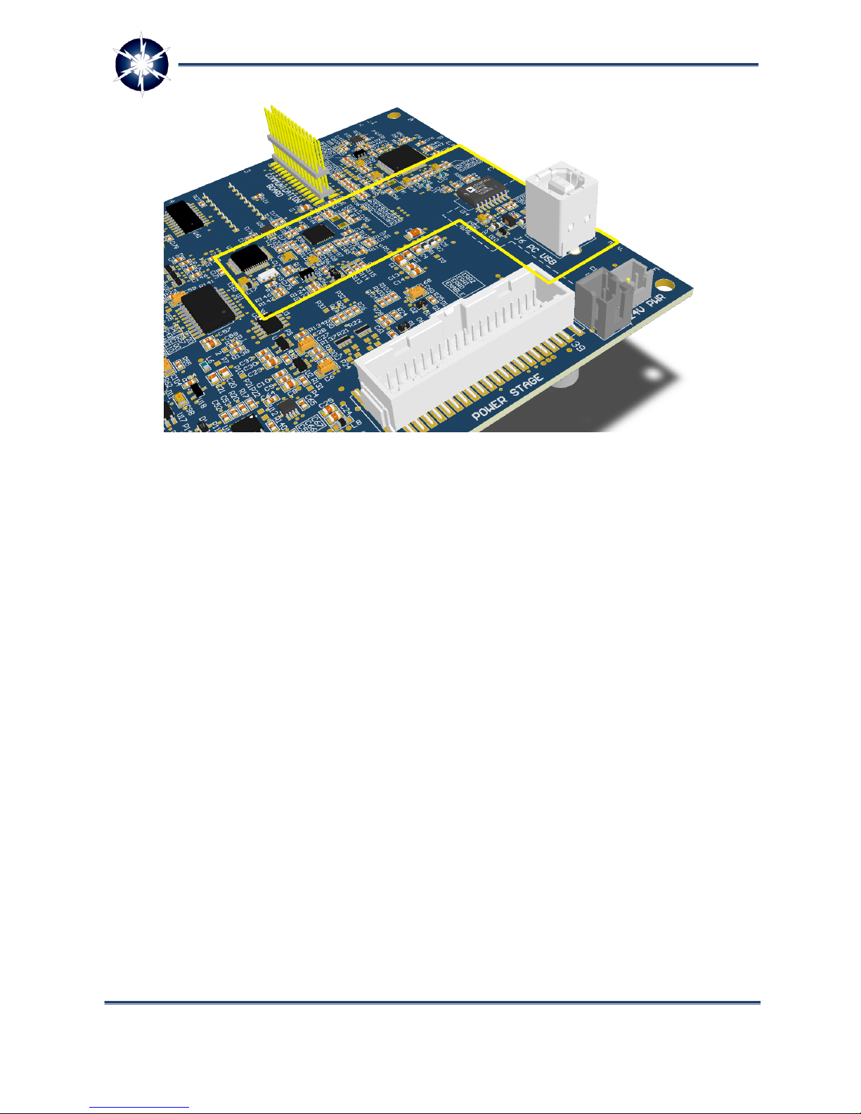
4 –USB interface –Configure, monitor and control your power electronics device through PERUN’s
PowerDesk software suite.
5 –Power Stage interface –Interface all control, feedback and protection signals of power stage in
appropriate and safe manner with your controller.
6 –GPIO Board interface –Take advantage of PERUN’s GPIO Boards, and expand functionality of your
power electronics device through different digital and analog inputs and outputs.
7 –Controller Board interface –LARA-100 Motherboard has DIMM100 socket for connecting the power
stage controller. This makes it plug-and-play compatible with wide range of Texas Instruments C2000
control cards. Just plug TMS320F28335 controlCARD, upload appropriate PERUN’s example code and
you are ready to control your power stage.
8 –JTAG selection switch –Select between on-board XDS100 JTAG programmer / debugger or external
programmer / debugger connected to the corresponding connector on PERUN’s Communication Board.
LARA-100 Motherboard is plug-and-play solution compatible with all Texas Instruments industry-
standard DIMM100 controlCards, such as TMDSCNCD28335 with TMS320F28335 high-performance
floating-point controller that operates at 150 MHz, has 256K x 16-bits Flash, 34K x 16-bits SRAM, and
I/O peripherals optimized for power electronics applications. Having sockets for Power Stage,
Application, GPIO and Communication Boards, LARA-100 Motherboard utilizes all of the controller’s
peripheral I/Os important for LARA-100 power electronics system control. This makes LARA-100 system
easy adaptable to various power electronics applications and different supervisory controllers.
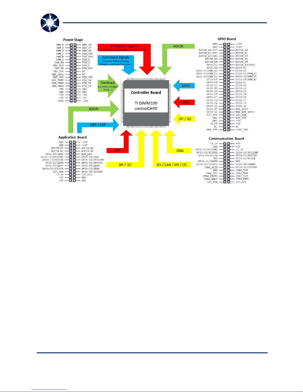
Motherboard functionalities can be extended by using various PERUN’s Application, GPIO and
Communication Boards. Figure 6 gives an overview of connections between TI DIMM100 Control Cards
and Motherboard’s main connectors.
Power Electronics Research Unified Technologies
www.perun-power.com
11
PERUN Technologies
Figure 7: Pinout of LARA 100 Motherboard connectors and overview of controller
connections
Controller on-board JTAG programmer/debugger
To make your control prototyping experience as convenient as possible, LARA-100 Motherboard has
built-in XDS100 v1 JTAG programmer/debugger. User can use standard programming/debugging
environment, such as Texas Instruments Code Composer Studio, or directly program and debug his
controller with PERUN PowerDesk software. He just needs to connect Motherboard with dedicated USB
link to the programming environment and he is ready to upload control code. Optionally, desired
external JTAG programmer/debugger can be used by connecting it to the controller through our
Communication Boards. Motherboard’s USB/JTAG interface, and moreover JTAG interface on
Communication Boards, are galvanically isolated from user’s programming/debugging device.
Power Electronics Research Unified Technologies
www.perun-power.com
12
PERUN Technologies
Figure 8: Controller on-board JTAG programmer/debugger interface
Control code debugging
By using PERUN PowerDesk software user can efficiently eradicate mistakes and iron out control code in
various applications, such as motor drive, PV boost converter or grid-connected converter in order to
work according to set requirements. It’s project-organized easy-to-use software environment used for
configuration, monitoring and high-level control of whole LARA-100 system. It’s special features are
Scope function allowing user to monitor any of controller’s real-time variables and Tag Explorer for
setting control variables and parameters reference values, turning the PERUN PowerDesk into ideal
platform for high-level debugging of power electronics applications. Motherboard’s USB/UART
debugging interface is galvanically isolated from user’s programming/debugging device (PC with PERUN
PowerDesk software). Moreover, you can use PERUN PowerDesk for control code high-level debugging
of any embedded microcontroller system with integrated USB/UART bridge.

Power Electronics Research Unified Technologies
www.perun-power.com
13
PERUN Technologies
Figure 9: Control code debugging
Technical specification for Motherboard
LARA-100 Motherboard dimensions and fixture holes are carefully designed in order to fit into the
original cover box of the industrial power converter. Just replace original controller board with PERUN
Motherboard, connect Motherboard and Power Stage with dedicated connector, and Power Stage is
ready for use. There is no need for multitude of long wires connecting the controller and power stage
units, controller is nicely packed locally where the power stage is, making the whole LARA-100 system
much less sensitive to signal noise typical for power electronics devices switching nature. In that way,
complete LARA-100 system have external layout as industrial drives, which is not usual case with open
development platforms.
www.perun-
power.com
Power Electronics Research Unified Technologies
www.perun-power.com
14
PERUN Technologies
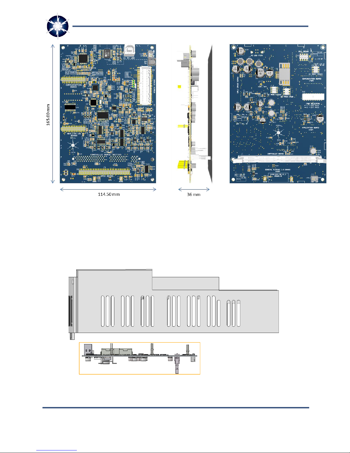
Figure 10: LARA 100 Motherboard dimensions
Following figures represent process of mounting Motherboard on the industrial power stage (only
mechanical cover is shown).

Power Electronics Research Unified Technologies
www.perun-power.com
15
PERUN Technologies
Figure 11: Power Stage cover box and LARA-100 Motherboard aligned for mounting –look
from the left (upper figure). Power Stage cover box and mounted LARA-100 Motherboard –
look from the front (bottom figure).
Figure 12: Power Stage cover box and mounted LARA-100 Motherboard. Look from the top
and bottom.

Power Electronics Research Unified Technologies
www.perun-power.com
16
PERUN Technologies
Figure 13: Power Stage cover box and mounted LARA-100 Motherboard, ready for
connection to Power Stage, LARA-100 Expansion Boards (GPIO, APP, COMM) and PC with
PERUN PowerDesk software.
Motherboard’s top side connectors are properly aligned with cover box holes, and at the bottom side
there is a connector (J1) for Controller Board.
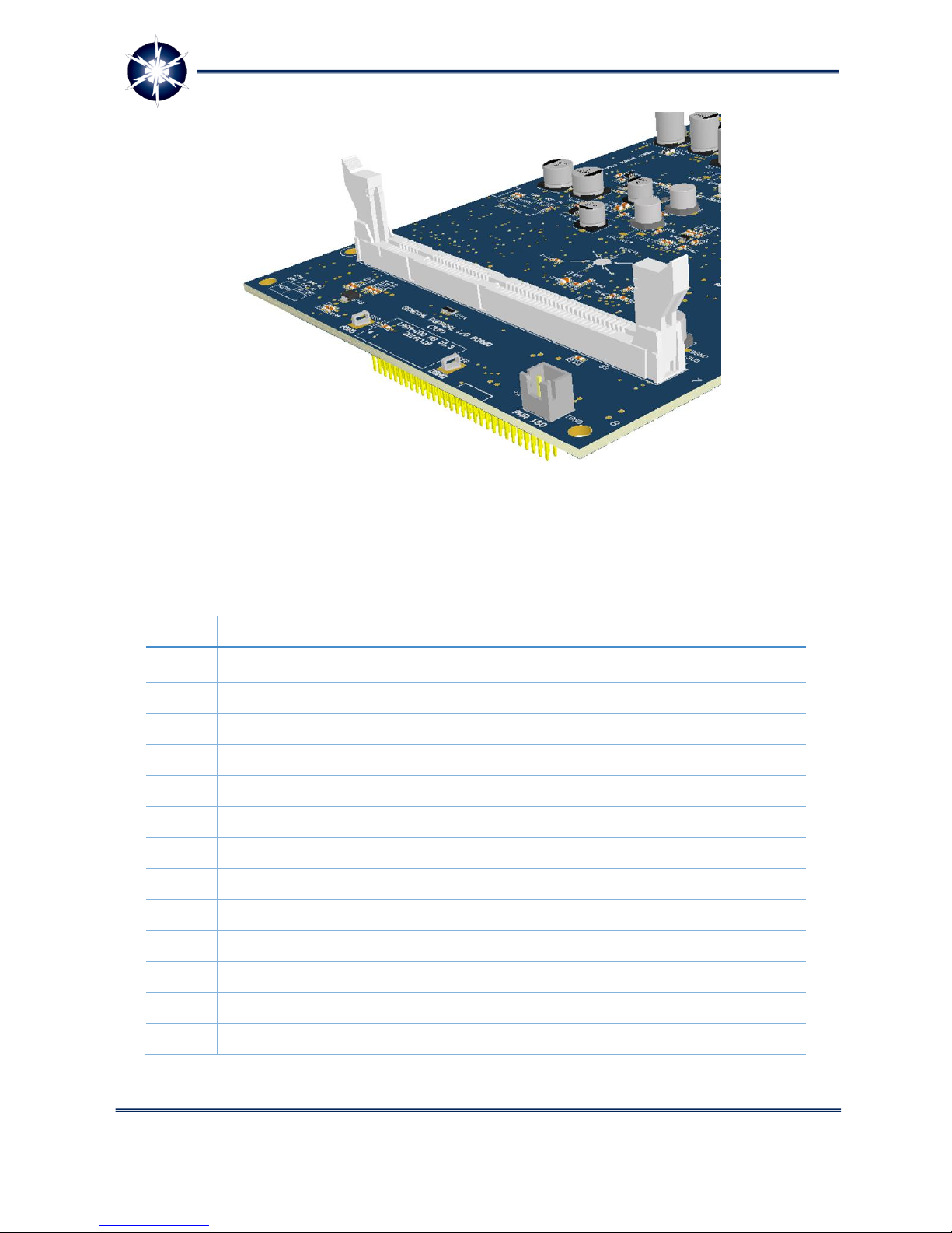
Connections –Controller Board (J1)
LARA-100 Motherboard has DIMM100 connector (TE Connectivity part number 5390213-1, standard
MO-161) for direct use with compatible Texas Instruments controlCARDs or custom made Controller
Boards. It is placed on the bottom side of Motherboard, in the slot shown in Figure 14.
Power Electronics Research Unified Technologies
www.perun-power.com
17
PERUN Technologies
Figure 14: Controller board connector (J1)
A pin assignment of controller board connector is given in following table:
Table 1: Pin assignment of controller board interface (J1)
Pin
Signal
Description
1
N.C.
Not used
2
N.C.
Not used
3
N.C.
Not used
4
N.C.
Not used
5
N.C.
Not used
6
N.C.
Not used
7
N.C.
Not used
8
N.C.
Not used
9
N.C.
Not used
10
N.C.
Not used
11
N.C.
Not used
12
N.C.
Not used
13
ADCIN-B0
Controller analog input B0

Power Electronics Research Unified Technologies
www.perun-power.com
18
PERUN Technologies
Pin
Signal
Description
14
DSP_IU/ADCIN-A0
Measured inverter line current IU
15
GND
Electronics ground reference
16
GND
Electronics ground reference
17
ADCIN-B1
Controller analog input B1
18
DSP_IV/ADCIN-A1
Measured inverter line current IV
19
GND
Electronics ground reference
20
GND
Electronics ground reference
21
ADCIN-B2
Controller analog input B2
22
DSP_IW/ADCIN-A2
Measured inverter line current IW
23
GND
Electronics ground reference
24
GND
Electronics ground reference
25
ADCIN-B3
Controller analog input B3
26
DSP_VDC/ADCIN-A3
Measured DC-link voltage
27
GND
Electronics ground reference
28
GND
Electronics ground reference
29
ADCIN-B4
Controller analog input B4
30
DSP_TEMP/ADCIN-A4
Measured heatsink temperature
31
N.C.
Not used
32
N.C.
Not used
33
ADCIN-B5
Controller analog input B5
34
VREF/ADCIN-A5
Reference offset voltage (for currents)
35
PPD_RST/GPIO-58
Reset PERUN PowerDesk (PPD) scope
36
ERR_RST_DSP/GPIO-59
Error reset/acknowledgment
37
ADCIN-B6
Controller analog input B6
38
ADCIN-A6
Controller analog input A6
39
GPIO-60
Controller general purpose input/output 60
40
GPIO-61
Controller general purpose input/output 61
41
ADCIN-B7
Controller analog input B7
42
ERR_CODE/ADCIN-A7
Error code in analog format
43
GPIO-62/SCIRX-C
Controller GPIO or SCI pin 1)

Power Electronics Research Unified Technologies
www.perun-power.com
19
PERUN Technologies
Pin
Signal
Description
44
GPIO-63/SCITX-C
Controller GPIO or SCI pin 1)
45
DSP_GU/GPIO-
00/EPWM-1A
PWM signal for upper switch phase U
46
DSP_GX/GPIO-
01/EPWM-1B
PWM signal for lower switch phase U
47
DSP_GV/GPIO-
02/EPWM-2A
PWM signal for upper switch phase V
48
DSP_GY/GPIO-
03/EPWM-2B
PWM signal for lower switch phase V
49
DSP_GW/GPIO-
04/EPWM-3A
PWM signal for upper switch phase W
50
DSP_GZ/GPIO-
05/EPWM-3B
PWM signal for lower switch phase W
51
GPIO-06/EPWM-4A
Controller GPIO or PWM pin 1)
52
GPIO-07/EPWM-
4B/ECAP-2
Controller GPIO or PWM or CAP pin 1)
53
GND
Electronics ground reference
54
+5V
Power supply +5V for Controller Board
55
GPIO-08/EPWM-5A
Controller GPIO or PWM pin 1)
56
GPIO-09/EPWM-
5B/ECAP-3
Controller GPIO or PWM or CAP pin 1)
57
GPIO-10/EPWM-6A
Controller GPIO or PWM pin 1)
58
GPIO-11/EPWM-
6B/ECAP-4
Controller GPIO or PWM or CAP pin 1)
59
DSP_VUV/GPIO-
48/ECAP-5
Measured inverter output voltage VUV
60
PWM_EN/GPIO-49
PWM enable signal
61
N.C.
Not used
62
N.C.
Not used
63
N.C.
Not used
64
+5V
Power supply +5V for Controller Board
65
ERR/GPIO-12/TZ-1
Error signal (indicating error state) 1)
66
ERR_DSP/GPIO-13
Controller error triggering signal
Other manuals for LARA-100 COMM
2
Table of contents
Other Perun Technologies Motherboard manuals


Popular Motherboard manuals by other brands


Texas Instruments
Texas Instruments ADS1263EVM-PDK user guide

Anadigm
Anadigm RangeMaster5 quick start guide

Analog Devices
Analog Devices EV-TEMPSENSE-ARDZ user guide

Linear Technology
Linear Technology Analog Devices DC1890A Demo Manual

Linear Technology
Linear Technology DC1472A Demo Manual

Linear Technology
Linear Technology DC1525B-D Demo Manual


