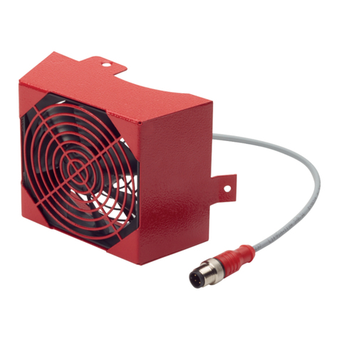
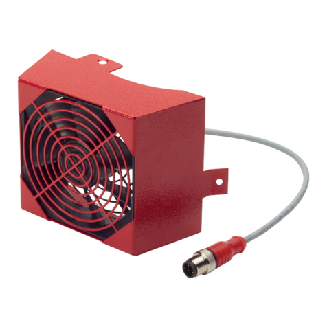
Pfeiffer Vacuum PM Z01 367 User manual

OPERATING INSTRUCTIONS
EN
Translation of the Original
HIPACE NEO
Air cooling

Dear customer,
Thank you for choosing a Pfeiffer Vacuum product. Your new Pfeiffer Vacuum accessory
should support you in your individual application with full performance and without
malfunctions. The name Pfeiffer Vacuum stands for high-quality vacuum technology, a
comprehensive and complete range of top-quality products and first-class service. With this
expertise, we have acquired a multitude of skills contributing to an efficient and secure
implementation of our product.
Knowing that our product must not interfere with your actual work, we are convinced that our
product offers you the solution that supports you in the effective and trouble-free execution of
your individual application.
Please read these operating instructions before putting your product into operation for the
first time. If you have any questions or suggestions, please feel free to contact info@pfeiffer-
vacuum.de.
Further operating instructions from Pfeiffer Vacuum can be found in the Download Center on
our website.
Disclaimer of liability
These operating instructions describe all models and variants of your product. Note that your
product may not be equipped with all features described in this document. Pfeiffer Vacuum
constantly adapts its products to the latest state of the art without prior notice. Please take
into account that online operating instructions can deviate from the printed operating
instructions supplied with your product.
Furthermore, Pfeiffer Vacuum assumes no responsibility or liability for damage resulting from
the use of the product that contradicts its proper use or is explicitly defined as foreseeable
misuse.
Copyright
This document is the intellectual property of Pfeiffer Vacuum and all contents of this
document are protected by copyright. They may not be copied, altered, reproduced or
published without the prior written permission of Pfeiffer Vacuum.
We reserve the right to make changes to the technical data and information in this document.
2/18

Table of contents
1 About this manual 6
1.1 Validity 6
1.1.1 Applicable documents 6
1.1.2 Variants 6
1.2 Target group 6
1.3 Conventions 6
1.3.1 Instructions in the text 6
1.3.2 Pictographs 7
1.3.3 Abbreviations 7
1.3.4 Stickers on the product 7
2 Safety 8
2.1 General safety information 8
2.2 Safety precautions 8
2.3 Limits of use of the product 9
2.4 Proper use 9
2.5 Foreseeable misuse 9
2.6 Personnel qualification 9
3 Product description 10
3.1 Function 10
3.2 Identifying the product 10
3.3 Scope of delivery 10
4 Connecting air cooling 11
5 Operation 13
6 Technical data and dimensions 15
6.1 Technical data 15
6.2 Dimensions 15
Declaration of Conformity 16
Table of contents
3/18

List of tables
Tbl. 1: Applicable documents 6
Tbl. 2: Versions of the air cooling for turbopumps 6
Tbl. 3: Abbreviations used in this document 7
Tbl. 4: Stickers on the product 7
Tbl. 5: Permissible ambient and operating conditions 9
Tbl. 6: Parameter settings for USB-connection to the turbopump 13
Tbl. 7: Parameter settings for M8- connection to the electronic drive unit 13
Tbl. 8: Air cooling, 24 V DC 15
List of tables
4/18

1 About this manual
IMPORTANT
Read carefully before use.
Keep the manual for future consultation.
1.1 Validity
This operating instructions is a customer document of Pfeiffer Vacuum. The operating instructions de-
scribe the functions of the named product and provide the most important information for the safe use of
the device. The description is written in accordance with the valid directives. The information in this op-
erating instructions refers to the product's current development status. The document shall remain valid
provided that the customer does not make any changes to the product.
1.1.1 Applicable documents
Designation Document
Declaration of conformity A component of these instructions
Tbl. 1: Applicable documents
You can find this document in the Pfeiffer Vacuum Download Center.
1.1.2 Variants
Version with USB connector Versions with M8 connector assembly
● HiPace 80 Neo ● TC 80
● TC 110
● TC 110 RS
● TC 120
● TCP 350
Tbl. 2: Versions of the air cooling for turbopumps
1.2 Target group
This operating instructions is intended for persons who
●install,
●operate.
The work described in this document may be carried out only by people who have completed suitable
technical training (experts), or who have received equivalent training from Pfeiffer Vacuum.
1.3 Conventions
1.3.1 Instructions in the text
Usage instructions in the document follow a general structure that is complete in itself. The required ac-
tion is indicated by an individual step or multi-part action steps.
Individual action step
A horizontal, solid triangle indicates the only step in an action.
►This is an individual action step.
Sequence of multi-part action steps
The numerical list indicates an action with multiple necessary steps.
1. Step 1
2. Step 2
3. ...
About this manual
6/18

1.3.2 Pictographs
Pictographs used in the document indicate useful information.
Note
Tip
1.3.3 Abbreviations
Abbreviation Meaning in this document
DC Direct current
M8 Metric thread size, nominal size 8 mm
WAF Width Across Flats
TC Electronic drive unit (turbo controller)
USB Universal Serial Bus
Tbl. 3: Abbreviations used in this document
1.3.4 Stickers on the product
This section describes all the stickers on the product along with their meanings.
Mod.: Air cooling USB
Mod.-Nr.: PM Z01 367
D-35641 Asslar
Made in Germany
Input: 24 V/DC
11/2021
Rating plate (example)
The rating plate is located on the bottom of the mounting bracket
Tbl. 4: Stickers on the product
1
2
Fig. 1: Position of the sticker on the product
1 Rating plate 2 Mounting bracket
About this manual
7/18

2 Safety
2.1 General safety information
The following 4 risk levels and 1 information level are taken into account in this document.
DANGER
Immediately pending danger
Indicates an immediately pending danger that will result in death or serious injury if not observed.
►Instructions to avoid the danger situation
WARNING
Potential pending danger
Indicates a pending danger that could result in death or serious injury if not observed.
►Instructions to avoid the danger situation
CAUTION
Potential pending danger
Indicates a pending danger that could result in minor injuries if not observed.
►Instructions to avoid the danger situation
NOTICE
Danger of damage to property
Is used to highlight actions that are not associated with personal injury.
►Instructions to avoid damage to property
Notes, tips or examples indicate important information about the product or about this docu-
ment.
2.2 Safety precautions
Duty to provide information on potential dangers
The product holder or user is obliged to make all operating personnel aware of dangers
posed by this product.
Every person who is involved in the installation, operation or maintenance of the product
must read, understand and adhere to the safety-related parts of this document.
Infringement of conformity due to modifications to the product
The Declaration of Conformity from the manufacturer is no longer valid if the operator
changes the original product or installs additional equipment.
●Following the installation into a system, the operator is required to check and re-evalu-
ate the conformity of the overall system in the context of the relevant European Direc-
tives, before commissioning that system.
General safety precautions when handling the product
►Observe all applicable safety and accident prevention regulations.
►Check that all safety measures are observed at regular intervals.
►Never disconnect plug connections during operation.
►Keep lines and cables away from hot surfaces (> 70 °C).
►Observe the unit protection degree prior to installation or operation in other environments.
►Do not carry out your own conversions or modifications on the unit.
Safety
8/18

2.3 Limits of use of the product
Parameter Air cooling
Permissible ambient temperature of the turbopump max. +35 °C1)
Protection degree IP20
Relative humidity of air ≤ 85 % not condensing
Tbl. 5: Permissible ambient and operating conditions
2.4 Proper use
►Use the air cooling exclusively for cooling Pfeiffer Vacuum turbopumps within the limits of use de-
scribed.
►Adhere to the installation, commissioning, operating, and maintenance instructions.
►Do not use any accessory parts other than those recommended by Pfeiffer Vacuum.
2.5 Foreseeable misuse
Improper use of the product invalidates all warranty and liability claims. Any use that is counter to the
purpose of the product, whether intentional or unintentional, is regarded as improper use, in particular:
●Connection to vacuum pumps or equipment which are not suitable for this purpose according to
their operating instructions
●Connection to equipment with exposed live parts
2.6 Personnel qualification
The work described in this document may only be carried out by persons who have appropriate profes-
sional qualifications and the necessary experience or who have completed the necessary training as
provided by Pfeiffer Vacuum.
Training people
1. Train the technical personnel on the product.
2. Only let personnel to be trained work with and on the product when under the supervision of
trained personnel.
3. Only allow trained technical personnel to work with the product.
4. Before starting work, make sure that the commissioned personnel have read and understood
these operating instructions and all applicable documents, in particular the safety, maintenance
and repair information.
1) Water cooling is required for higher ambient temperatures
Safety
9/18

3 Product description
3.1 Function
Pfeiffer Vacuum recommends using air cooling in processes with high gas throughput, bad fore-vacuum
pressure and/or high ambient temperatures. If the cooling capacity of the air cooling is insufficient, use
water cooling instead.
The air cooling with USB connector is intended for direct connection to the turbopump. As an alterna-
tive, there is a version with M8 plug-and-socket connectors for connection to the electronic drive unit.
1
2
3
Fig. 2: Layout of air cooling
1 Fan housing 3 Control cable with power supply plug
2 Mounting bracket
3.2 Identifying the product
►To ensure clear identification of the product when communicating with Pfeiffer Vacuum, always
keep all of the information on the rating plate to hand.
3.3 Scope of delivery
The scope of delivery includes the following parts:
●Air cooling
●Mounting kit (separate package)
●Operating instructions
Product description
10/18

4 Connecting air cooling
NOTICE
Property damage to third-party electronic devices
The accessory connections on the vacuum pump do not meet any USB standard. The connection as-
signment does not comply with any standard. Depending on their configuration, the 24 V DC supply
voltage may damage or destroy third-party electronic devices, e.g. tablet computer.
►Do not connect any third-party electronic devices to the accessory connections.
►Only use the connecting sockets for pump-specific accessories.
Prerequisites
●Turbopump switched off and vented
Required tools
●Open-end wrench, WAF 7
1
2
7
5
3
6
4
Fig. 3: Example: Connecting air cooling to HiPace 80 Neo
1 Sealing plugs 5 Hexagon head screw
2 Control cable 6 Mounting surface for mounting on the side
3 Hole pattern for mounting on the rear 7 Accessory connections "C1" and "D1"
4 Air cooling
Connecting the air cooling to the turbopump using the USB plug
1. Fix the air cooling at the threaded holes provided to the pump bottom part using the screws from
the mounting kit.
2. Connect the control cable of the air cooling to one of the two accessory connections "C1" or "D1"
on the pump bottom part.
–The software of the electronic drive unit automatically resets existing configuration settings to
“default”.
–The software of the electronic drive unit automatically recognizes connected accessories.
Connecting air cooling
11/18

Connecting the air cooling to the electronic drive unit using M8 plug-and-socket connection
1. Fix the air cooling at the threaded holes provided to the pump bottom part using the screws from
the mounting kit.
2. Screw the control cable onto the accessory ports of the plug-and-socket connection for the elec-
tronic drive unit.
3. Manually configure the desired accessory output for the air cooling via the interfaces of the elec-
tronic drive unit.
–The specification for the air cooling is "accessory A1".
Connecting air cooling
12/18

5 Operation
Important settings and function-related variables are programmed ex factory as parameters in the vac-
uum pump electronic drive unit. Each parameter has a three-digit number and a description. Parameter-
driven operation and control is supported via Pfeiffer Vacuum displays and control units, or externally
via RS-485 using Pfeiffer Vacuum protocol.
Parame-
ter
Name Designation Adjustment/comment de-
fault
[P:068] CfgAccC1 Accessory connec-
tion C1
0 = fan (continuous operation)
4 = fan (temperature controlled)
6 = Always "0"
7 = Always "1"
0
[P:069] CfgAccD1 Accessory connec-
tion D1
0 = fan (continuous operation)
4 = fan (temperature controlled)
6 = Always "0"
7 = Always "1"
0
[P:728] fanOnTemp Start-up temperature
of the fan in tempera-
ture-controlled mode
45 °C (in the pump bottom part, tempera-
ture can be read via [P:330])
45
Tbl. 6: Parameter settings for USB-connection to the turbopump
Parame-
ter
Name Designation Adjustment/comment de-
fault
[P:035] CfgAccA1 Accessory con-
nection A1
0 = fan (continuous operation)
4 = fan (temperature controlled)
6 = Always "0"
7 = Always "1"
0
[P:036] CfgAccB1 Accessory con-
nection B1
0 = fan (continuous operation)
4 = fan (temperature controlled)
6 = Always "0"
7 = Always "1"
1
[P:037]2) CfgAccA2 Accessory con-
nection A2
0 = fan (continuous operation)
2 = heating
3 = backing pump
4 = fan (temperature controlled)
6 = Always "0"
7 = Always "1"
3
[P:038]3) CfgAccB2 Accessory con-
nection B2
0 = fan (continuous operation)
2 = heating
3 = backing pump
4 = fan (temperature controlled)
6 = Always "0"
7 = Always "1"
2
[P:728]4) fanOnTemp Start-up tempera-
ture of the fan in
temperature-con-
trolled mode
45 °C (in the pump bottom part, temperature
can be read via [P:330])
45
Tbl. 7: Parameter settings for M8- connection to the electronic drive unit
2) Depending on type
3) Depending on type
4) Depending on type
Operation
13/18

Information regarding commissioning of the turbopump with air cooling
●Continuous operation: The fan runs in continuous operation as soon as voltage is supplied.
●Temperature-controlled: The fan runs according to the switch point settings in parameter
[P:728].
Operation
14/18

6 Technical data and dimensions
6.1 Technical data
Type designation Air cooling, shielded Air cooling, screened
Part number PM Z01 367 PM Z01 369
Pump HiPace 80 Neo HiPace 30 | HiPace 60 P | HiPace 80 | HiPace 80
Neo | SplitFlow 50 / 80
Electronic drive unit TC 80 TC 110, TC 110 RS, TC 120, TCP 350, TC 80
Control voltage 24 V DC 24 V DC
Electrical connection Micro USB M8
Tbl. 8: Air cooling, 24 V DC
6.2 Dimensions
0
1
28
45
60
61
1,7
5
30
n4,5
Fig. 4: Dimensions - Air cooling
Dimensions in mm
Technical data and dimensions
15/18

Declaration of Conformity
Declaration for product(s) of the type:
Air cooling
HiPace Neo
SplitFlow
We hereby declare that the listed product satisfies all relevant provisions of the following
European Directives.
Electromagnetic compatibility 2014/30/EU
Restriction of the use of certain hazardous substances 2011/65/EU
Restriction of the use of certain hazardous substances, delegated directive
2015/863/EU
Harmonized standards and applied national standards and specifications:
DIN EN 61000-3-2 : 2019
DIN EN 61000-3-3 : 2020
DIN EN 61326-1 : 2018
DIN VDE 0580 : 2011
Signature:
Pfeiffer Vacuum GmbH
Berliner Straße 43
35614 Asslar
Germany
(Daniel Sälzer)
Managing Director
Asslar, 2022-07-28

17/18

*PT0739* ed. C - Date 2207 - P/N:PT0739BEN
This manual suits for next models
1
Table of contents
Other Pfeiffer Vacuum Air Conditioner manuals
Popular Air Conditioner manuals by other brands

Crosley
Crosley 2020213A Use & care manual

Mitsubishi Electric
Mitsubishi Electric MSC-GE20VB operating instructions

Toshiba
Toshiba RAV-RM561KRTP-E installation manual

Hitachi
Hitachi RAS-18LH2 Service manual

GE
GE AEZ10AVL1 Owner's manual and installation instructions

Tokyo Gas
Tokyo Gas MISTY IBD-4110ACSKJ3M manual