Pfeiffer Vacuum HiPace Series User manual

PT 0500 BEN/B (1605)
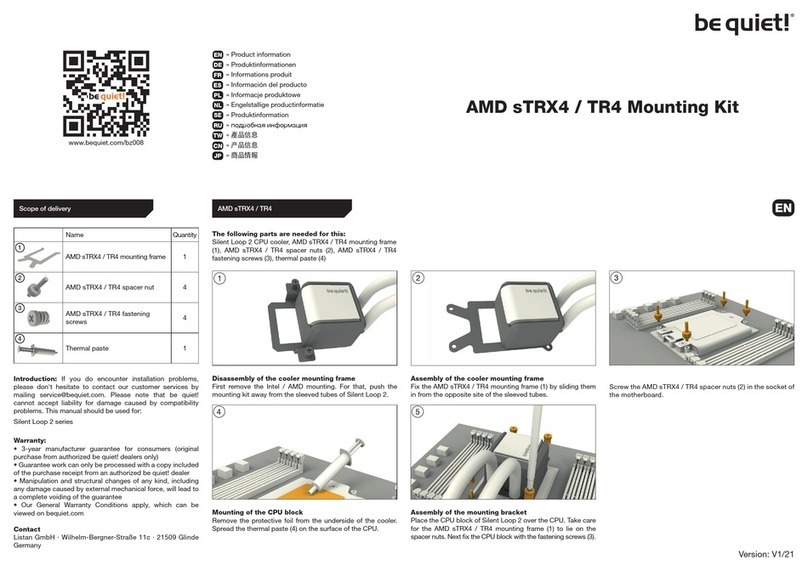
OPERATING INSTRUCTIONS EN
Translation of the original instructions
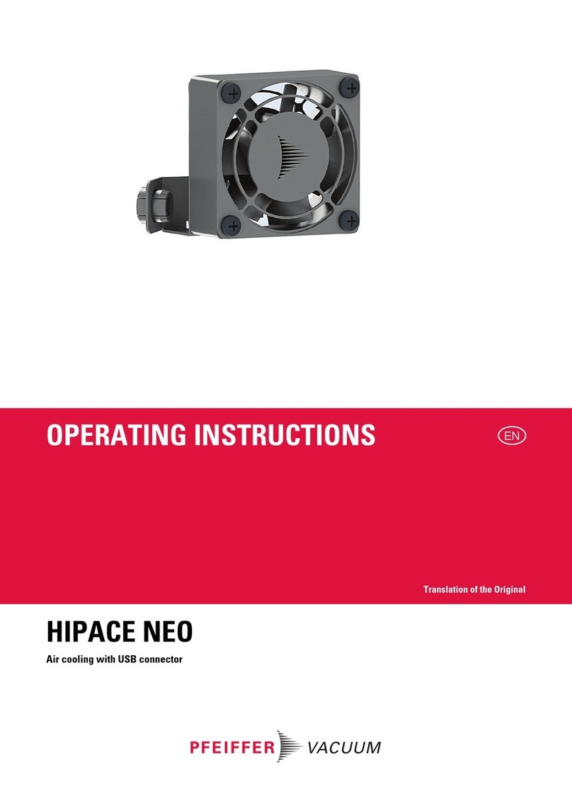
HIPACE AIR COOLING UNIT

Table of contents
2
Table of contents
1 Validity . . . . . . . . . . . . . . . . . . . . . . . . . . . . . . . . . . . . . . . . . . . . . . . . . . . . . . . . 3
2 Proper use . . . . . . . . . . . . . . . . . . . . . . . . . . . . . . . . . . . . . . . . . . . . . . . . . . . . . 3
3 Air cooling units, 24 V DC. . . . . . . . . . . . . . . . . . . . . . . . . . . . . . . . . . . . . . . . . 3
3.2 HiPace 60 P, HiPace 80, SplitFlow 50 . . . . . . . . . . . . . . . . . . . . . . . . . . . . 4
3.3 HiPace 300, TC 110/TC 120 . . . . . . . . . . . . . . . . . . . . . . . . . . . . . . . . . . . . 4
3.4 HiPace 300, TC 400 . . . . . . . . . . . . . . . . . . . . . . . . . . . . . . . . . . . . . . . . . . 5
3.5 HiPace 400, HiPace 700, HiPace 800 . . . . . . . . . . . . . . . . . . . . . . . . . . . . 5
4 Air cooling units, 115 / 230 V DC . . . . . . . . . . . . . . . . . . . . . . . . . . . . . . . . . . . 6
4.1 HiPace 60 P, HiPace 80, SplitFlow 50 . . . . . . . . . . . . . . . . . . . . . . . . . . . . 6
4.2 HiPace 300, 400, 700, 800 . . . . . . . . . . . . . . . . . . . . . . . . . . . . . . . . . . . . . 6
4.3 Electrical connection . . . . . . . . . . . . . . . . . . . . . . . . . . . . . . . . . . . . . . . . . . 7
5 Air cooling units, 24 V DC for TeleTC cable 400. . . . . . . . . . . . . . . . . . . . . . . 7
6 Dimensions . . . . . . . . . . . . . . . . . . . . . . . . . . . . . . . . . . . . . . . . . . . . . . . . . . . . 8
Declaration of conformity. . . . . . . . . . . . . . . . . . . . . . . . . . . . . . . . . . . . . . . . . 9

Validity
3
1ValidityThis operating manual is for customers of Pfeiffer Vacuum. It describes the functioning
of the designated product and provides the most important information for safe use of
the unit. The description follows applicable EU guidelines. All information provided in this
operating manual refers to the current state of the product's development. The documen-
tation remains valid as long as the customer does not make any changes to the product.
Up-to-date operating instructions can also be downloaded from
www.pfeiffer-vacuum.com.
2 Proper use
●The air cooling serves to the cooling of Pfeiffer Vacuum turbopumps at ambient tem-
peratures of max. + 35 °C.
●Type selection according to the accessories recommendation of the respective tur-
bopump.
Improper use will cause all claims for liability and warranties to be forfeited. Improper use
is defined as usage for purposes deviating from those mentioned above, especially:
●connection to pumps or units which are not suitable for this purpose according to their
operating instructions
●connection to units which have exposed voltage-carrying parts
3 Air cooling units, 24 V DC
3.1 HiPace 30
Fix the air cooling unit to the holes of the turbopump using two screws.
Plug in and fix the accessory’s control lead to a free connection port on the connecting
cable or adapter of the electronic drive unit.
Standard:
Shielded variants
PM Z01 300 A
PM Z01 348 A
PM Z01 360 A
PM Z01 301 A
PM Z01 361 A
PM Z01 302 A
PM Z01 362 A
PM Z01 303 A
PM Z01 363 A
Power consumption 1.32 W 3.84 W 3.84 W 3.84 W
Control voltage 24 V DC 24 V DC 24 V DC 24 V DC
Electric connection M8 M8 M12 M12
Fig. 1: Connecting the air cooling
3 Pump lower part
3a Air cooling unit
3b Hexagon screw
33b
3a

4
Air cooling units, 24 V DC
Make the settings and control via the interfaces of the electronic drive unit.
3.2 HiPace 60 P, HiPace 80, SplitFlow 50
Fix the air cooling unit to the holes of the turbopump using two screws.
Plug in and fix the accessory’s control lead to a free connection port on the connecting
cable or adapter of the electronic drive unit.
Make the settings and control via the interfaces of the electronic drive unit.
3.3 HiPace 300, TC 110/TC 120
Fix the air cooling unit to the holes of the turbopump using two screws.
Plug in and fix the accessory’s control lead to a free connection port on the connecting
cable or adapter of the electronic drive unit.
Make the settings and control via the interfaces of the electronic drive unit.
Fig. 2: Connecting the air cooling
3 Pump lower part
3a Air cooling unit
3b Hexagon screw
33b
3a
Fig. 3: Connecting the air cooling
3 Pump lower part
3a Air cooling unit
3b Allen head screw
3c Counter-sunk screw
3
3a
3b
3c

Air cooling units, 24 V DC
5
3.4 HiPace 300, TC 400
Fix the air cooling unit to the holes of the turbopump using two screws.
Plug in and fix the accessory’s control lead to the corresponding accessory connection
port on the electronic drive unit.
Make the settings and control via the interfaces of the electronic drive unit.
3.5 HiPace 400, HiPace 700, HiPace 800
Fix the air cooling unit to the holes of the turbopump using two screws.
Plug in and fix the accessory’s control lead to the corresponding accessory connection
port on the electronic drive unit.
Make the settings and control via the interfaces of the electronic drive unit.
Fig. 4: Connecting the air cooling
3 Pump lower part
3a Air cooling unit
3b Allen head screw
3c Counter-sunk screw
3
3a
3b
3c
Fig. 5: Connecting the air cooling
3 Pump lower part
3a Air cooling unit
3b Allen head screw
3c Counter-sunk screw
3a
3b
3c
3

6
Air cooling units, 115 / 230 V DC
4 Air cooling units, 115 / 230 V DC
4.1 HiPace 60 P, HiPace 80, SplitFlow 50
Scope of delivery
●Air cooling unit
●Mounting bracket
●3 pieces Allen head screw M4x8
●1 piece countersink screw M5x10
●3 pieces washer
Fix mounting bracket 51 with two Allen head screws 52 at the pump bottom part.
Fix fan housing 15 with Allen head screw 52 at mounting bracket.
Fix fan housing at the pump. Depending on the use of rubber feet:
–A: Fixing with one rubber foot 320. Thereby compensate the remaining three rub-
ber feet 320 with a washer 58 each.
–B: Fixing with countersink screw 55 without use of rubber feet.
4.2 HiPace 300, 400, 700, 800
The installation of the air cooling unit 115/230 V DC to the turbopump is analogous to
the 24 V DC version of the same pump type.
PM Z01 343 A PM Z01 344 A
Mains connection: voltage 230 V AC 115 V AC
Power consumption at 50 Hz 13 W 12 W
Power consumption at 60 Hz 10 W 9 W
Electric connection field attachable
51
52
52
15
51
58
320
15 15
A
55
B
PM Z01 308 A PM Z01 309 A PM Z01 341 A PM Z01 342 A
Netzanschluss 115 V AC 230 V AC 230 V AC 115 V AC
Power consumption at 50 Hz 12 W 13 W 13 W 12 W
Power consumption at 50 Hz 9 W 10 W 10 W 9 W
Electric connection field attachable

Air cooling units, 24 V DC for TeleTC cable 400
7
4.3 Electrical connection
5 Air cooling units, 24 V DC for TeleTC cable 400
Scope of delivery
●Air cooling unit
●1 piece hexagon nut M4
●1 piece spring-ring
The electronic drive unit must be cooled additionally, when the respective ambient tem-
peratures are attained.
For connection and operation of the accessory please refer to the operating instruc-
tions for the Tele TC cable 400 (PT 0310 BN).
Fix the air cooling to the free borehole of the electronic drive unit, using the installation
material (enclosure) and the remaining third allen head screw (57c).
Plug in and fix the accessory’s control lead to the corresponding accessory connection
port on the electronic drive unit.
DANGER
Voltage-bearing elements
Danger to life from electric shock as a result of improper installation.
Electrical connection may be carried out only by trained and authorised electricians.
Ensure the system is adequately earthed.
Establish an adequate fuse protection on customer side (depending on the model).
WARNING
Danger of unsafe electrical installation
Safe operation after installation is the responsibility of the operator.
Do not independently modify or change the pump and electrical equipment.
Make sure that the system is integrated in an emergency off safety circuit.
Consult Pfeiffer Vacuum for special requirements.
Standard:
Shielded variants:
PM Z01 304 A
PM Z01 364 A
Control voltage 24 V DC
Power consumption 1.32 W
Electric connection M12
Fig. 6: Mounting an air cooling unit to the electronic drive unit
57c Allen head screw
802 Adapter, TC side
850 Air cooling unit
855 Hexagon nut
856 Spring washer
802
57c 850
855
856

8
Dimensions
6 Dimensions
Fig. 7: PM Z01 300 A, PM Z01 348 A, PM Z01 360 A
Fig. 8: PM Z01 304 A, PM Z01 364 A
Fig. 9: PM Z01 301 A, PM Z01 302 A, PM Z01 308 A, PM Z01 309 A,PM Z01 343 A, PM Z01 344 A,
PM Z01 361 A, PM Z01 362 A
Fig. 10: PM Z01 303 A, PM Z01 363 A, PM Z01 341 A, PM Z01 342 A
85.3
36.9
81.2
4.5
Ø9
20
8
63
30
85.3
56.9
8
20
Ø9
81.2
4.5
63
30
141.1
68.3
137.8
97
139.3
64.6
135.9
97

Declaration of conformity
We hereby declare that the product cited below satisfies all relevant provisions accord-
ing to the following EC directives:
●Electromagnetic Compatibility 2014/30/EU
●Low Voltage 2014/35/EU
●Restriction of the use of certain Hazardous Substances 2011/65/EU
Air Cooling Unit
Harmonised standards and national standards and specifications which have been ap-
plied:
DIN EN 61010
Signature:
Pfeiffer Vacuum GmbH
Berliner Straße 43
35614 Asslar
Germany
(Dr. Ulrich von Hülsen)
Managing Director
2016-05-04

VACUUM SOLUTIONS FROM A SINGLE SOURCE
Pfeiffer Vacuum stands for innovative and custom vacuum solutions worldwide,
technological perfection, competent advice and reliable service.
COMPLETE RANGE OF PRODUCTS
From a single component to complex systems:
We are the only supplier of vacuum technology that provides a complete product portfolio.
COMPETENCE IN THEORY AND PRACTICE
Benefit from our know-how and our portfolio of training opportunities!
We support you with your plant layout and provide first-class on-site service worldwide.
Are you looking for a
perfect vacuum solution?
Please contact us:
Pfeiffer Vacuum GmbH
Headquarters • Germany
T +49 6441 802-0
www.pfeiffer-vacuum.com
This manual suits for next models
10
Table of contents
Other Pfeiffer Vacuum Computer Hardware manuals
Popular Computer Hardware manuals by other brands

Microchip Technology
Microchip Technology Photodiode PGAPICtail user guide
Lenovo
Lenovo SP41E22346 Instructions for use
IWL
IWL KMAX Series quick start
SeaLevel
SeaLevel COMM+8.422.PCIe user manual
Grifco
Grifco EB1 installation manual
MikroTik
MikroTik RouterBOARD 411UAHR Quick setup guide and warranty information
