6
Transport and storage
3 Transport and storage
3.1 Transport
Parts of the system are dismounted prior to transport, so these much be re-installed
according to the installation drawing.
4 Product description
4.1 Product identification
To correctly identify the product when communicating with Pfeiffer Vacuum, always have
the information from the rating plate available.
Scope of delivery The condensers can be delivered in the following designs:
– Cooling surface between 0.5 and 12 m2
– Housing in normal and stainless steel design
– Condensate drainage either through manual valves or automatic drainage control
Other special application-specific designs are possible.
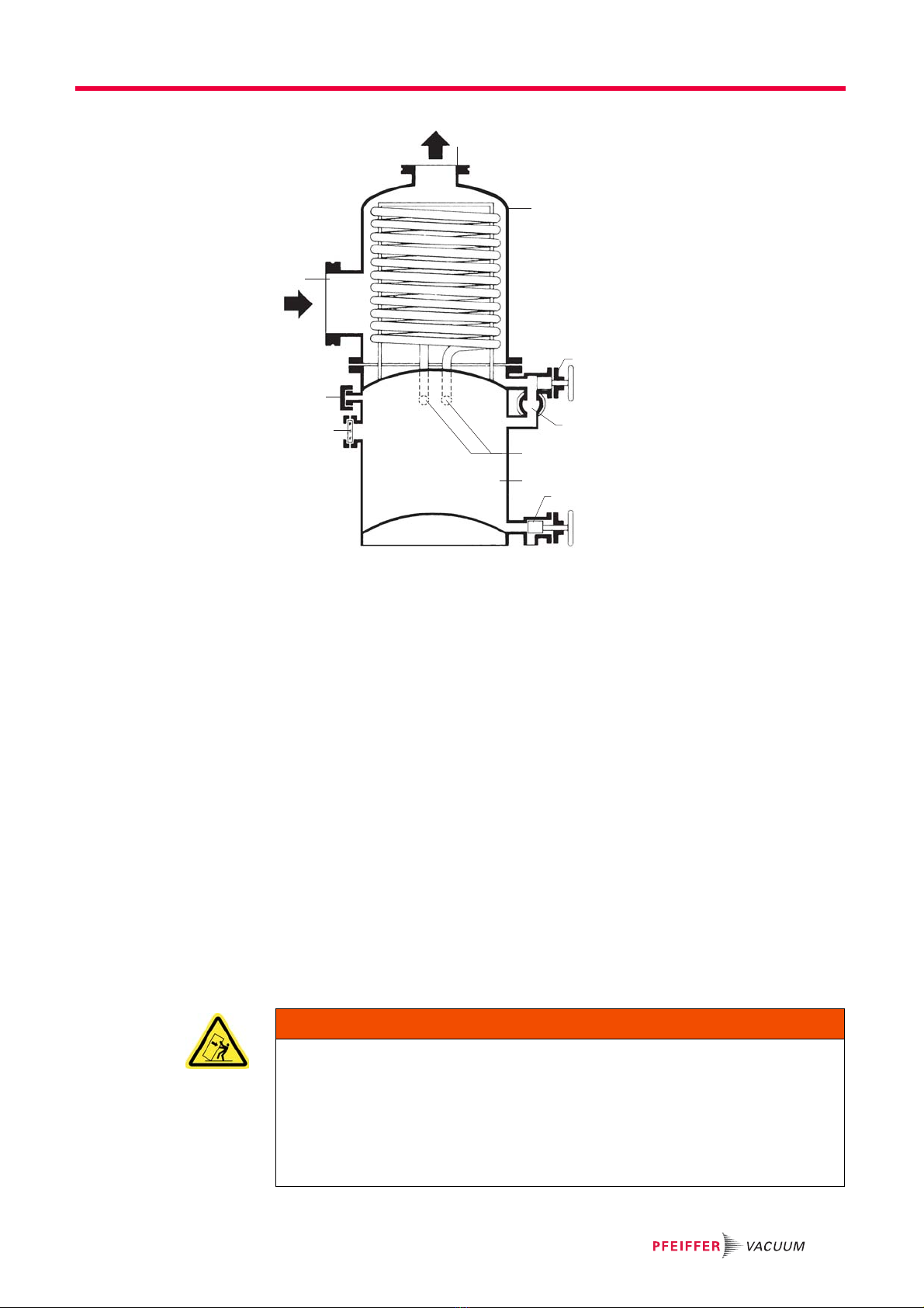
4.2 Function
The purpose of the condenser is to condense steam before it enters the vacuum pump,
in order to protect the vacuum pump against damaging condensates and to ensure the
permitted partial pressure of the vacuum pressure is not exceeded. This preserves the
lubricity of the operating materials and the achievable ultimate pressure of the vacuum
pump.
The effectiveness of the condenser is limited by the cooling water temperature and the
procedure used. Steam condensation is in principle only possible up to the saturation
pressure of the respective substance. In order to maintain an optimum performance of
the condenser, the cooling water inlet temperature should not normally exceed 15°C.
In condensation compartment 3, the cooling surface is formed by a stainless steel coiled
tube through which water flows. The steam exiting from the vacuum chamber condenses
on the cooling surface and flows as condensate into the collection container 4.
Thanks to the set-up of the non-return valve V3, the use of a ventilation valve V4 and a
condensate outlet screw V5, the condensate produced can be drained off without inter-
rupting batches.
WARNING
There is a risk of injury if the system is not transported properly.
Danger to life from falling or protruding loads if the system is not properly secured to lift-
ing devices or is not transported properly.
Use suitable lifting devices and tools.
Ensure that the weight is distributed evenly (danger of tipping!).
Test the hanging for high center of gravity.
The set-up and size of the gas intake and exhaust nozzles is based on the cus-
tomer's requirements.
These can sometimes differ considerably from the illustrations shown in these operating
instructions. The component drawing with the respective article number of the condens-
er is the authoritative reference for the position of the nozzles and connectors.