Pfeiffer Vacuum QMH 40 Series User manual

OPERATING INSTRUCTIONS
EN
Translation of the Original
QMH 40X
High-frequency generator for QMG 700 HiQuad®

Dear Customer,
Thank you for choosing a Pfeiffer Vacuum product. Your new high-frequency generator is
designed to support you in your individual application with full performance and without
malfunctions. The name Pfeiffer Vacuum represents high-quality vacuum technology, a
comprehensive and complete range of top-quality products and first-class service. From this
extensive, practical experience we have gained a large volume of information that can
contribute to efficient deployment and to your personal safety.
In the knowledge that our product must avoid consuming work output, we trust that our
product can offer you a solution that supports you in the effective and trouble-free
implementation of your individual application.
Please read these operating instructions before putting your product into operation for the
first time. If you have any questions or suggestions, please feel free to contact info@pfeiffer-
vacuum.de.
Further operating instructions from Pfeiffer Vacuum can be found in the Download Center on
our website.
Disclaimer of liability
These operating instructions describe all models and variants of your product. Note that your
product may not be equipped with all features described in this document. Pfeiffer Vacuum
constantly adapts its products to the latest state of the art without prior notice. Please take
into account that online operating instructions can deviate from the printed operating
instructions supplied with your product.
Furthermore, Pfeiffer Vacuum assumes no responsibility or liability for damage resulting from
the use of the product that contradicts its proper use or is explicitly defined as foreseeable
misuse.
Copyright
This document is the intellectual property of Pfeiffer Vacuum and all contents of this
document are protected by copyright. They may not be copied, altered, reproduced or
published without the prior written permission of Pfeiffer Vacuum.
We reserve the right to make changes to the technical data and information in this document.
2/48

Table of contents
1 About this manual 7
1.1 Validity 7
1.1.1 Applicable documents 7
1.1.2 Variants 7
1.2 Target group 7
1.3 Conventions 8
1.3.1 Instructions in the text 8
1.3.2 Pictographs 8
1.3.3 Stickers on the product 8
1.3.4 Abbreviations 8
1.4 Trademark proof 9
2 Safety 10
2.1 General safety information 10
2.2 Safety instructions 10
2.3 Safety precautions 12
2.4 Limits of use of the product 12
2.5 Proper use 13
2.6 Foreseeable improper use 13
2.7 Responsibilities and warranty 13
2.8 Owner requirements 13
2.9 Personnel qualification 14
2.9.1 Ensuring personnel qualification 14
2.9.2 Personnel qualification for maintenance and repair 14
2.9.3 Advanced training with Pfeiffer Vacuum 14
2.10 Operator requirements 15
3 Product description 16
3.1 Structure 16
3.2 Functional description 16
3.3 Connections 17
3.3.1 QC connection to QC 700 control unit 17
3.3.2 Connections FA and RF+ / RF- to the QMA analyzer 18
3.3.3 EP connection to EP 422 electrometer pre-amplifier 19
3.4 Identifying the product 19
3.5 Scope of delivery 19
4 Transport and storage 21
4.1 Transporting the product 21
4.2 Storing the product 21
5 Installation 22
5.1 Installing the HF generator 22
5.1.1 Observing ambient conditions 22
5.1.2 Observing mounting orientation 23
5.1.3 Installing high-frequency generator with support on QMA 23
5.2 Establishing an electrical connection 24
5.2.1 Establishing grounding connection 24
5.2.2 Connecting control cable 25
5.2.3 Connecting HF coaxial cables 25
5.2.4 Connecting field axis cable 25
5.2.5 Connecting electrometer pre-amplifiers 25
6 Commissioning 26
6.1 Waiting time 26
6.2 Checking tuning 26
Table of contents
3/48

7 Operation 28
7.1 Measuring spectra 28
7.2 Selecting integral spectrum 28
7.3 Setting the resolution 28
7.4 Adjusting resolution for low masses (LOW) 28
7.5 Calibrating mass scale (MASS CALIBRATION LOW/HIGH) 29
7.6 Waiting times 29
8 Maintenance 30
8.1 Maintaining product 30
8.2 Cleaning device 31
9 Malfunctions 32
10 Shipping 35
11 Recycling and disposal 36
11.1 General disposal information 36
11.2 Dispose of a mass spectrometer system 36
12 Service solutions by Pfeiffer Vacuum 37
13 Ordering information 39
13.1 Ordering parts 39
13.2 Ordering spare parts and accessories 39
14 Technical data and dimensions 40
14.1 Technical data 40
14.2 Electrical data 40
14.3 Working data with quadrupole analyzer 41
14.4 Dimensions 42
15 Appendix 43
15.1 Behavior as a function of time 43
15.1.1Step response 43
15.1.2Fast mass scans 43
15.2 Calibration method for mass number M and line width ΔM 43
15.2.1Apparent peak position and line width 44
15.2.2Apparent peak position and peak shape 44
15.2.3Definition of mass number and line width 44
15.2.4Deviations from M and ΔM 45
EC Declaration of Conformity 46
UK Declaration of Conformity 47
Table of contents
4/48

List of tables
Tbl. 1: Applicable documents 7
Tbl. 2: Abbreviations used 8
Tbl. 3: Permissible ambient conditions 13
Tbl. 4: Pin assignment of QC connection 17
Tbl. 5: Functions 18
Tbl. 6: Coding 18
Tbl. 7: Pin assignment of FA connection 18
Tbl. 8: Pin assignment of RF+ and RF- connections 18
Tbl. 9: Pin assignment of EP connection 19
Tbl. 10: Indicators at illuminated bar 26
Tbl. 11: Preferred calibration points 28
Tbl. 12: Preferred calibration points 29
Tbl. 13: Malfunctions 34
Tbl. 14: Spare parts 39
Tbl. 15: Accessories 39
Tbl. 16: Technical data 40
Tbl. 17: Ambient conditions 40
Tbl. 18: Electrical data 41
Tbl. 19: QMH and QMA types 41
Tbl. 20: Working data with quadrupole analyzer 42
Tbl. 21: Waiting periods for QMH engagement 43
Tbl. 22: Mass scale lag 43
List of tables
5/48

List of figures
Fig. 1: Structure 16
Fig. 2: Pin assignment of QC connection 17
Fig. 3: Pin assignment of FA connection 18
Fig. 4: Pin assignment of EP connection 19
Fig. 5: Max. permissible heat development 22
Fig. 6: Horizontal mounting plane and permissible inclination 23
Fig. 7: Installing high-frequency generator with support on QMA 23
Fig. 8: 6 possible installation positions 24
Fig. 9: Illuminated bar: "tuning" 26
Fig. 10: Non-linearity of M and ΔM 42
Fig. 11: Dimensions 42
Fig. 12: The peak top moves with ΔM 44
Fig. 13: The peak top moves with the peak shape 44
Fig. 14: Calibration method for mass number M and line width ΔM 44
Fig. 15: 1 = Measured peak | 2 = Reference peak ΔM = 1 u 45
List of figures
6/48
1 About this manual
IMPORTANT
Read carefully before use.
Keep the manual for future consultation.
1.1 Validity
This document describes the function of the products listed in the following and provides the most im-
portant information for safe use. The description is written in accordance with the valid directives. The
information in this document refers to the current development status of the products. The document
retains its validity assuming that the customer does not make any changes to the product.
1.1.1 Applicable documents
Designation Document
Operating instructions for "HiQuad" QMG 700 BG 5400
Operating instructions for EP 422 electrometer pre-amplifier
Operating instructions for CP 400 ion counter pre-amplifier BG 5812
Operating instructions for IO 720 input-output module BG 5402
Operating instructions for QMA 4x0 analyzer BG 5983
QUADERA software documentation (part of the software)
Declaration of conformity (part of these instructions)
Tbl. 1: Applicable documents
You can find these documents in the Pfeiffer Vacuum Download Center.
1.1.2 Variants
This document applies to products with the following article numbers:
Article number Designation
PT M23 067 QMH 400-1
PT M23 066 QMH 400-5
PT M23 070 QMH 402-2
You can find the part number on the rating plate of the product.
Pfeiffer Vacuum reserves the right to make technical changes without prior notification.
The figures in this document are not to scale.
Dimensions are in mm unless stated otherwise.
1.2 Target group
These operating instructions are aimed at all persons performing the following activities on the product:
●Transportation
●Setup (Installation)
●Usage and operation
●Decommissioning
●Maintenance and cleaning
●Storage or disposal
The work described in this document is only permitted to be performed by persons with the appropriate
technical qualifications (expert personnel) or who have received the relevant training from Pfeiffer Vac-
uum.
About this manual
7/48
1.3 Conventions
1.3.1 Instructions in the text
Usage instructions in the document follow a general structure that is complete in itself. The required ac-
tion is indicated by an individual step or multi-part action steps.
Individual action step
A horizontal, solid triangle indicates the only step in an action.
►This is an individual action step.
Sequence of multi-part action steps
The numerical list indicates an action with multiple necessary steps.
1. Step 1
2. Step 2
3. ...
1.3.2 Pictographs
Pictographs used in the document indicate useful information.
Note
Tip
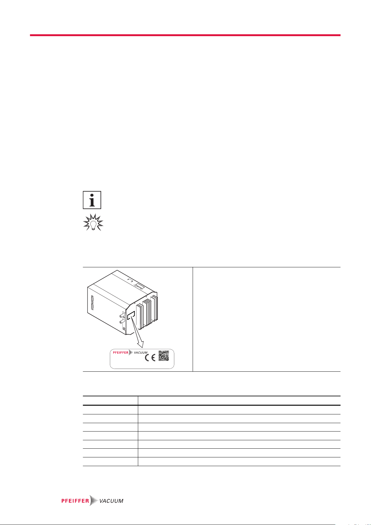
1.3.3 Stickers on the product
This section describes all the stickers on the product along with their meanings.
D-35614 Asslar
Mod.
P/N
S/N
Input
QMH 4xx-x
PT Mxx xxx
xxxxxxxxx
24 V DC 110 W
Made in United States 2022/07
Rating plate
The rating plate is located on the side of the unit.
1.3.4 Abbreviations
Abbreviation Explanation
ESD Electrostatic discharge
FA Field axes
HF High frequency
QMA Quadrupole mass spectrometer analyzer
QMH Quadrupole mass spectrometer high-frequency generator
RF Radio frequency (high frequency)
SEM Secondary electron multiplier
Tbl. 2: Abbreviations used
About this manual
8/48

1.4 Trademark proof
●HiQuad® is a registered trademark of Pfeiffer Vacuum GmbH.
●QUADERA ® is a registered trademark of Inficon GmbH.
About this manual
9/48

2 Safety
2.1 General safety information
The following 4 risk levels and 1 information level are taken into account in this document.
DANGER
Immediately pending danger
Indicates an immediately pending danger that will result in death or serious injury if not observed.
►Instructions to avoid the danger situation
WARNING
Potential pending danger
Indicates a pending danger that could result in death or serious injury if not observed.
►Instructions to avoid the danger situation
CAUTION
Potential pending danger
Indicates a pending danger that could result in minor injuries if not observed.
►Instructions to avoid the danger situation
NOTICE
Danger of damage to property
Is used to highlight actions that are not associated with personal injury.
►Instructions to avoid damage to property
Notes, tips or examples indicate important information about the product or about this docu-
ment.
2.2 Safety instructions
Safety instructions according to product life stages
All safety instructions in this document are based on the results of a risk assessment.
Pfeiffer Vacuum has taken into account all the relevant life stages of the product.
Risks during installation
DANGER
Danger to life from electric shock
Inadequate or incorrect grounding of the unit leads to contact-sensitive voltage on the housing. When
making contact, increased leakage currents will cause a life-threatening electric shock.
►Before the installation, check that the connection leads are voltage-free.
►Conduct the electrical connection in accordance with locally applicable regulations.
►Make sure that the local mains voltage and frequency match rating plate specifications.
►Make sure that the mains cable and extension cable meet the requirements for double isolation
between input voltage and output voltage, in accordance with IEC 61010 and IEC 60950.
►Use only a 3-pin mains cable and extension cable with properly connected protective earthing
(earthed conductor).
►Plug the mains plug into a socket with earthing contact only.
►Always connect the mains cable prior to all other cables, to ensure continuous protective earth-
ing.
Safety
10/48

Risks during operation
DANGER
Danger to life from electric shock caused by moisture ingress
Water that has entered the unit will result in personal injury through electric shocks.
►Only operate the unit in a dry environment.
►Operate the unit away from fluids and sources of moisture.
►Do not switch on the unit if fluid has entered it. Instead contact Pfeiffer Vacuum Service.
►Always disconnect the power supply before cleaning the unit.
Risks during maintenance
DANGER
Danger to life due to electric voltage
High voltages are present inside the device. When touching parts that are live, there is a risk of
death. If there is visible damage, there is a risk of death when commissioning the device.
►Work on the open device must only be carried out by trained specialist personnel.
►Before carrying out any installation and maintenance work, switch the device off and disconnect
it from the current supply.
–After switching off, wait about 60 seconds and then disconnect all cables (power cable at the
end).
►Never open the device with the current supply connected.
►Secure the current supply against unauthorized or unintentional reactivation.
►Do not insert any objects into the vent openings.
►Never open an external power supply pack.
►Never operate an open or defective device.
►Secure a defective device against accidental operation.
►Protect the device against moisture.
WARNING
Health hazard through poisoning from toxic contaminated components or devices
Toxic process media result in contamination of devices or parts of them. During maintenance work,
there is a risk to health from contact with these poisonous substances. Illegal disposal of toxic sub-
stances causes environmental damage.
►Take suitable safety precautions and prevent health hazards or environmental pollution by toxic
process media.
►Decontaminate affected parts before carrying out maintenance work.
►Wear protective equipment.
WARNING
Health hazards due to cleaning agent
The cleaning agent being used causes health hazards which could include, for example, poisoning,
allergies, skin irritations, chemical burns or damage to the airways.
►When handling cleaning agents, observe the applicable regulations.
►Adhere to safety measures regarding handling and disposal of cleaning agents.
►Be aware of potential reactions with product materials.
Risks when shipping
WARNING
Risk of poisoning from contaminated products
Where products that contain harmful substances are shipped for maintenance or repair purposes, the
health and safety of service personnel is at risk.
►Comply with the instructions for safe distribution.
Safety
11/48
Risks during disposal
WARNING
Health hazard through poisoning from toxic contaminated components or devices
Toxic process media result in contamination of devices or parts of them. During maintenance work,
there is a risk to health from contact with these poisonous substances. Illegal disposal of toxic sub-
stances causes environmental damage.
►Take suitable safety precautions and prevent health hazards or environmental pollution by toxic
process media.
►Decontaminate affected parts before carrying out maintenance work.
►Wear protective equipment.
2.3 Safety precautions
The product is designed according to the latest technology and recognized safety engineering rules.
Nevertheless, improper use can result in danger to operator all third party life and limb, and product
damage and additional property damage.
Duty to provide information on potential dangers
The product holder or user is obliged to make all operating personnel aware of dangers
posed by this product.
Every person who is involved in the installation, operation or maintenance of the product
must read, understand and adhere to the safety-related parts of this document.
Infringement of conformity due to modifications to the product
The Declaration of Conformity from the manufacturer is no longer valid if the operator
changes the original product or installs additional equipment.
●Following the installation into a system, the operator is required to check and re-evalu-
ate the conformity of the overall system in the context of the relevant European Direc-
tives, before commissioning that system.
General safety precautions when handling the product
►Observe all applicable safety and accident prevention regulations.
►Check that all safety measures are observed at regular intervals.
►Pass on safety instructions to all other users.
►Do not expose body parts to the vacuum.
►Always ensure a secure connection to the earthed conductor (PE).
►Never disconnect plug connections during operation.
►Observe the above shutdown procedures.
►Keep lines and cables away from hot surfaces (> 70 °C).
►Do not carry out your own conversions or modifications on the device.
►Observe the unit protection degree prior to installation or operation in other environments.
►Provide suitable touch protection, if the surface temperature exceeds 70 °C.
►Inform yourself about any contamination before starting work.
2.4 Limits of use of the product
Parameter Value
Installation location Weatherproof (internal space)
Protection degree IP 20
Protection class I
Installation altitude Max. 2000 m
Degree of pollution 2
Storage temperature -20 – +60 °C
Operating temperature 0 – +50 °C
Safety
12/48

Parameter Value
Cable temperature (HF/FA) Max. 200 °C
Relative humidity Max. 80% at temperatures up to +31 °C.
Linearly decreasing to 50% at +40 °C.
Tbl. 3: Permissible ambient conditions
2.5 Proper use
The high-frequency generator QMH 40x is a component of the QMG 700 HiQuad quadrupole mass
spectrometry system of Pfeiffer Vacuum and generates the HF and DC voltages required for the rod
system of the QMA quadrupole analyzer. The high-frequency generator is intended exclusively for use
as a power supply unit for a Pfeiffer Vacuum QMA 400, QMA 410 or QMA 430 quadrupole analyzer.
►Install, operate and maintain the product only in accordance with these operating instructions.
►Comply with the limits of use.
►Observe the technical data.
2.6 Foreseeable improper use
Improper use of the product invalidates all warranty and liability claims. Any use that is counter to the
purpose of the product, whether intentional or unintentional, is regarded as improper use; in particular:
●Use outside the limits of use in accordance with the technical data
●Use for measurements whose results determine the safety of persons or large values
●Use with corrosive or explosive media
●Use outdoors
●Use after technical changes (inside or outside on the product)
●Use with replacement or accessory parts that are not suitable or not approved
2.7 Responsibilities and warranty
Pfeiffer Vacuum shall assume no responsibilities and warranty if the operating company or a third party:
●disregards this document
●does not use the product for its intended purpose
●carries out any modifications to the product (conversions, changes, etc.) that are not listed in the
corresponding product documentation
●operates the product with accessories that are not listed in the corresponding product documenta-
tion
The operator is responsible for the process media used.
2.8 Owner requirements
Safety-conscious working
1. Only operate the product in a technically flawless state.
2. Operate the product in line with its intended purpose, safety and hazard-conscious and only in
compliance with these operating instructions.
3. Fulfill the following instructions and monitor the observation of the following instructions:
–Proper use
–Generally applicable safety instructions and accident prevention regulations
–International, national and locally applicable standards and guidelines
–Additional product-related guidelines and regulations
4. Only use original parts or parts approved by Pfeiffer Vacuum.
5. Keep the operating instructions available at the place of installation.
6. Ensure personnel qualification.
Safety
13/48
2.9 Personnel qualification
The work described in this document may only be carried out by persons who have appropriate profes-
sional qualifications and the necessary experience or who have completed the necessary training as
provided by Pfeiffer Vacuum.
Training people
1. Train the technical personnel on the product.
2. Only let personnel to be trained work with and on the product when under the supervision of
trained personnel.
3. Only allow trained technical personnel to work with the product.
4. Before starting work, make sure that the commissioned personnel have read and understood
these operating instructions and all applicable documents, in particular the safety, maintenance
and repair information.
2.9.1 Ensuring personnel qualification
Specialist for mechanical work
Only a trained specialist may carry out mechanical work. Within the meaning of this document, special-
ists are people responsible for construction, mechanical installation, troubleshooting and maintenance
of the product, and who have the following qualifications:
●Qualification in the mechanical field in accordance with nationally applicable regulations
●Knowledge of this documentation
Specialist for electrotechnical work
Only a trained electrician may carry out electrical engineering work. Within the meaning of this docu-
ment, electricians are people responsible for electrical installation, commissioning, troubleshooting, and
maintenance of the product, and who have the following qualifications:
●Qualification in the electrical engineering field in accordance with nationally applicable regulations
●Knowledge of this documentation
In addition, these individuals must be familiar with applicable safety regulations and laws, as well as the
other standards, guidelines, and laws referred to in this documentation. The above individuals must
have an explicitly granted operational authorization to commission, program, configure, mark, and earth
devices, systems, and circuits in accordance with safety technology standards.
Trained individuals
Only adequately trained individuals may carry out all works in other transport, storage, operation and
disposal fields. Such training must ensure that individuals are capable of carrying out the required activi-
ties and work steps safely and properly.
2.9.2 Personnel qualification for maintenance and repair
Advanced training courses
Pfeiffer Vacuum offers advanced training courses to maintenance levels 2 and 3.
Adequately trained individuals are:
●Maintenance level 1
─Customer (trained specialist)
●Maintenance level 2
─Customer with technical education
─Pfeiffer Vacuum service technician
●Maintenance level 3
─Customer with Pfeiffer Vacuum service training
─Pfeiffer Vacuum service technician
2.9.3 Advanced training with Pfeiffer Vacuum
For optimal and trouble-free use of this product, Pfeiffer Vacuum offers a comprehensive range of
courses and technical trainings.
For more information, please contact Pfeiffer Vacuum technical training.
Safety
14/48

2.10 Operator requirements
Observing relevant documents and data
1. Read, observe and follow this operating instruction and the work instructions prepared by the op-
erating company, in particular the safety and warning instructions.
2. Install, operate and maintain the product only in accordance with these operating instructions.
3. Carry out all work only on the basis of the complete operating instructions and applicable docu-
ments.
4. Comply with the limits of use.
5. Observe the technical data.
6. Please contact the Pfeiffer Vacuum Service Center if your questions on operation or maintenance
of the product are not answered in these operating instructions.
–You can find information in the Pfeiffer Vacuum service area.
Safety
15/48

3 Product description
3.1 Structure
7
3
8
3
9
6
12
34
5
Fig. 1: Structure
1 Control element: "mass calibration low/high" 6 Connection for electrometer pre-amplifier
"ep1 (faraday)"
2 Illuminated bar: "tuning" 7 Connection for electrometer pre-amplifier
"ep2 (sem)"
3 Connections for HF coaxial cables RF+ and
RF-
8 Grounding screw M4
4 Control element: "tune" 9 Connection for field axis voltage "FA"
5 Control element: "resolution low/coarse"
3.2 Functional description
System wiring of QMG 700 HiQuad
For details about system wiring, refer to the operating instructions of the QMG 700 HiQuad.
The QMH high-frequency generator generates the voltages required for operating a quadrupole mass
filter:
●HF component with quartz-stabilized frequency
●Superimposed DC component
High-quality HF circuits ensure low power consumption and low self-produced heat. A constant-temper-
ature furnace keeps the temperature influences low. The QMH must be connected to a precision-match-
ed HF load. This is done by connecting the analyzer using the supplied HF cables with accurately de-
fined capacity. Manufacturing tolerances can be compensated. During operation and set-up, the match-
ing condition is monitored and signaled by means of LEDs. The QMH is protected against overheating
and destruction resulting from a mismatched HF load, a short circuit or during no-load operation. The
field axis potential is supplied externally. Connections ep1 (Faraday) and ep2 (SEM) are used to con-
nect two EP 422 electrometer pre-amplifiers.
The QMS control unit supplies the power and control signals, and contains the electronics for process-
ing the electrometer signals. With the QMS control unit, the following functions of the QMH can be used:
●Mass number M (HF amplitude)
●Peak width ΔM
●Integral spectrum (DC-deactivated)
●RF OFF
●Electrometer range
●Electrometer signal 1 oder 2
The instrument reports operational readiness or error status to the QMS control unit.
Product description
16/48
3.3 Connections
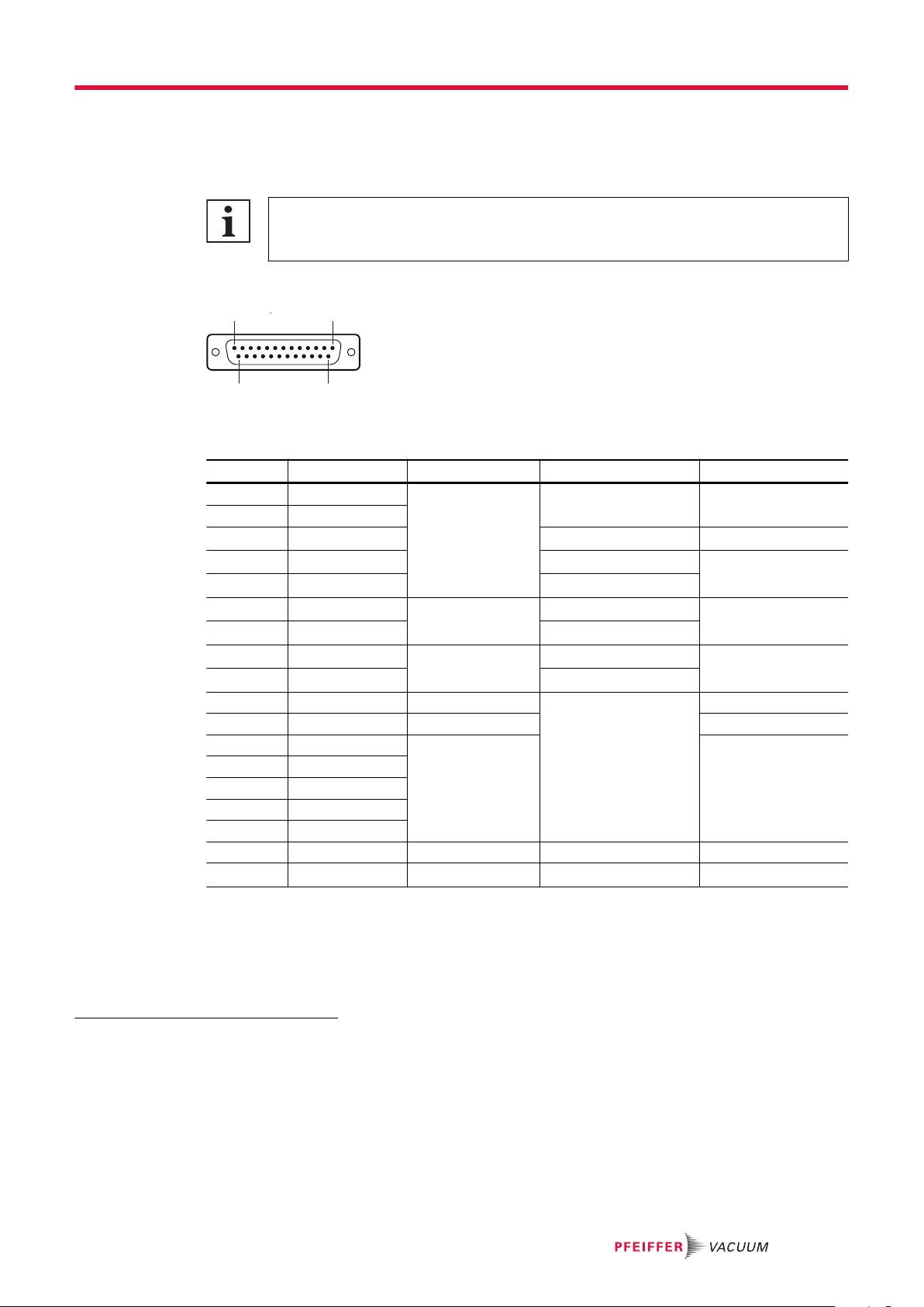
3.3.1 QC connection to QC 700 control unit
Interfaces on QC 700
For details about the interfaces on the QC 700, refer to the operating instructions of the
QMG 700 HiQuad.
At the QMH 4x0, there is a permanently installed 3 m connection cable for connection to the QC 700.
1
14
13
25
Fig. 2: Pin assignment of QC connection
Pin Signal word Signal direction Level Impedance
1,2,14 -24 V IN See "Technical data" Feed/supply
3,15,16 +24 V
4,6,17.19 0 V 1) GND 10 Ω (see Chassis)
5SCAN + 2) 0 – +10.24 V 100 kΩ
18 SCAN - 3) 0 V
7EP + 4) OUT 0 V 47 Ω
20 EP - 5) 0 – ±16 V
8RESOL + 6) IN 0 – +10.24 V 100 kΩ
21 RESOL - 7) 0 V
9 RESERVE 1 H IN Digital CMOS 8) 100 kΩ
10 RF OK L OUT 2.2 kΩ
11 MODE 1 H IN 100 kΩ pull down
23 MODE 2 H
12 RANGE 0 H
24 RANGE 1 H
13 EP 2 H
22 SCREEN --- GND 33 Ω (see Chassis)
25 RESERVE 2 H IN Digital CMOS 9) 100 kΩ pull down
Tbl. 4: Pin assignment of QC connection
Signal directions
●IN = QMH is receiver
●OUT = QMH is transmitter
1) Line 0 V must have max. ±0.5 Vp against chassis GND.
2) Permissible common-mode signal: max. ±0.5 Vp for SCAN±, RESOL± and EP±
3) Permissible common-mode signal: max. ±0.5 Vp for SCAN±, RESOL± and EP±
4) Permissible common-mode signal: max. ±0.5 Vp for SCAN±, RESOL± and EP±
5) Permissible common-mode signal: max. ±0.5 Vp for SCAN±, RESOL± and EP±
6) Permissible common-mode signal: max. ±0.5 Vp for SCAN±, RESOL± and EP±
7) Permissible common-mode signal: max. ±0.5 Vp for SCAN±, RESOL± and EP±
8) Digital CMOS level: L: 0 – +0.75 V DC | H: +11.0 – +12.7 V DC
9) Digital CMOS level: L: 0 – +0.75 V DC | H: +11.0 – +12.7 V DC
Product description
17/48

Signal word Level Function of QMH
SCAN± 0 – +10.24 V MASS = (SCAN/10.24 V) x Mmax
RESOL± 0 – +10.24 V ΔM = ΔMmin + (RESOL/10.24 V) x ΔMmax
EP± 0 – ±16 V Output signal of electrometer pre-amplifier (EP)
Tbl. 5: Functions
Signal word
RANGE – H ...1... ...0... Electrometer measuring range:
LL10-5 A
L H 10-7 A
H L 10-11 A
HH10-9 A
EP 2 H L ep1, faraday
H ep2, sem
MODE – H ...2... ...1... Operating mode:
L L STANDBY, not used
L H INTEGRAL (DC OFF)
H L SPECTRUM (DC ON)
H H RF OFF
RF OK L L QMH is OK
H QMH is not OK
Tbl. 6: Coding
3.3.2 Connections FA and RF+ / RF- to the QMA analyzer
Field axis voltage
For details on the field axis voltage, refer to the operating instructions of the QMA analyzer.
1 2
Fig. 3: Pin assignment of FA connection
Pin Signal word Signal direction Level Impedance
1 FA IN Max. ±500 V / 2 mAmax 9 MΩ
2 unassigned --- --- ---
Housing GND IN GND, shielding ---
Tbl. 7: Pin assignment of FA connection
Signal word Signal direction Level and load
RF+ and RF- OUT Adapted load
Housing OUT GND, shielding
Plug: coaxial, SHV
Tbl. 8: Pin assignment of RF+ and RF- connections
Product description
18/48
Signal directions
●IN = QMH is receiver
●OUT = QMH is transmitter
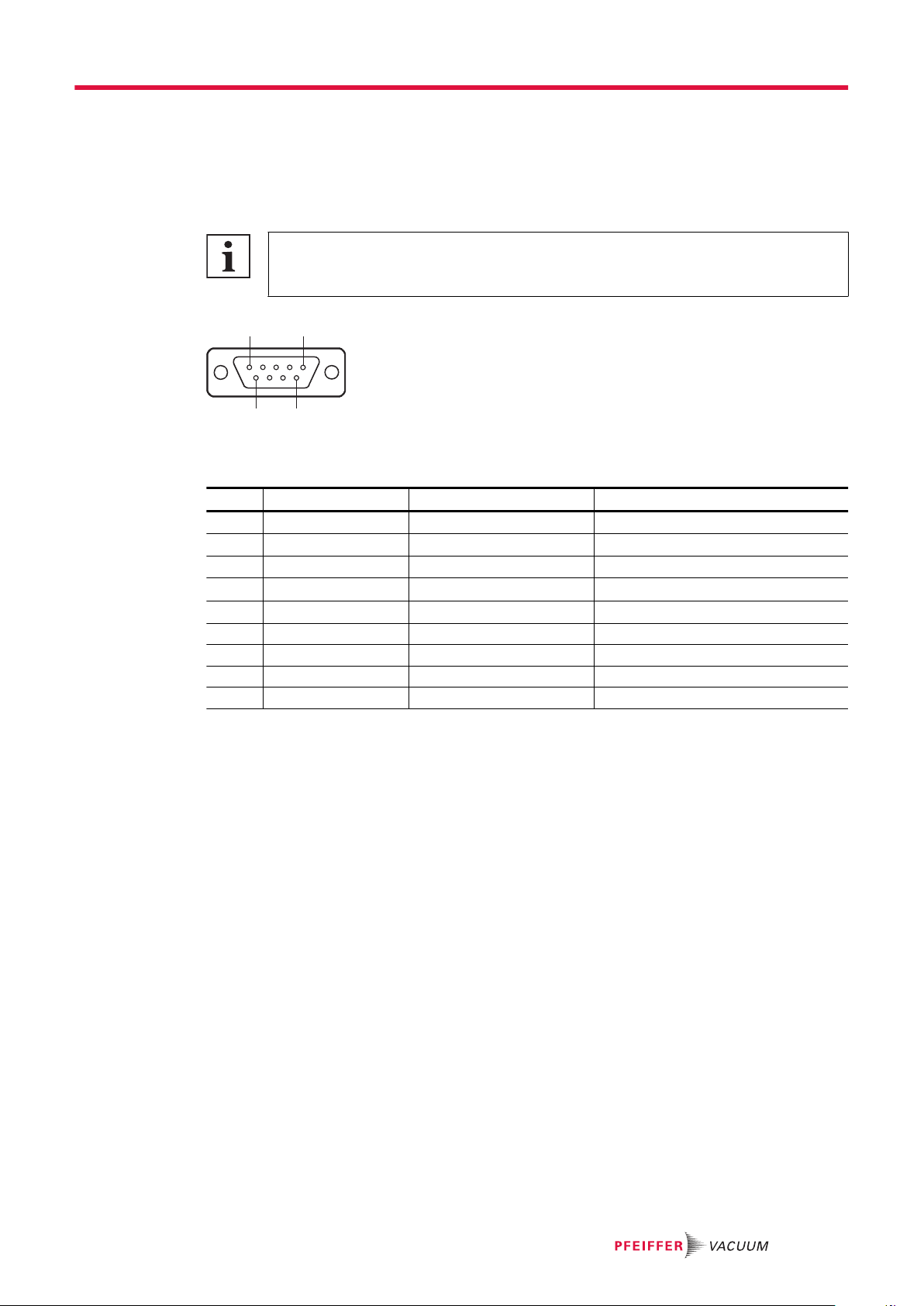
3.3.3 EP connection to EP 422 electrometer pre-amplifier
Interfaces on EP 422
For details about the interfaces on the EP 422, refer to the operating instructions of the
QMG 700 HiQuad.
9
5
6
1
Fig. 4: Pin assignment of EP connection
Pin Signal word Signal direction Level
1 EP GND IN 0 V
2 +16 V OUT +16 V ±0.2 V / 27 mAmax
3 0 V EP OUT EP GND
4 -16 V OUT -16 V ±0.2 V / 12 mAmax
5 EXP 5 L OUT Digital 1)
6 EP OUT IN 0 – ±16 V
7 SCREEN --- Chassis GND
8 EXP 7 L OUT Digital
9 EXP 9 L OUT Digital
Tbl. 9: Pin assignment of EP connection
Signal directions
●IN = QMH is receiver
●OUT = QMH is transmitter
Digital level
●L: 0 – +0.75 V DC
●H: +16.5 – +17.0 V DC with external pull-up >5 kΩ against +16 V
●The levels are relative to 0 V EP.
●With the exception of EP OUT and EP GND, the two plugs are connected in parallel.
3.4 Identifying the product
You will need all the data from the rating plate to safely identify the product when communicating with
Pfeiffer Vacuum.
►To ensure clear identification of the product when communicating with Pfeiffer Vacuum, always
keep all of the information on the rating plate to hand.
3.5 Scope of delivery
●QMH high-frequency generator
●Connection cable to QMS 700/QC 700, 3 m long (permanently attached to device)
Product description
19/48

Unpacking the product and checking completeness of the shipment
1. Unpack the product.
2. Check that the shipment is complete.
3. Ensure that no parts are damaged.
Product description
20/48
This manual suits for next models
6
Other Pfeiffer Vacuum Portable Generator manuals

Popular Portable Generator manuals by other brands

Honeywell
Honeywell 10 kW owner's manual

Winco
Winco HPS6000HE-03/A Installation & operator's manual

Pramac
Pramac GA20000 owner's manual

DuroStar
DuroStar DUROMAX DUAL FUEL XP8500EH user manual

Generac Power Systems
Generac Power Systems SE10000 owner's manual

Generac Power Systems
Generac Power Systems 7117 owner's manual


