Pfeiffer Vacuum TC 400 User manual

OPERATING INSTRUCTIONS
EN
Translation of the Original
TC 400
Electronic drive unit

Dear Customer,
Thank you for choosing a Pfeiffer Vacuum product. Your new turbopump is designed to
support you by its performance, its perfect operation and without interfering your individual
application. The name Pfeiffer Vacuum stands for high-quality vacuum technology, a
comprehensive and complete range of top-quality products and first-class service. With this
expertise, we have acquired a multitude of skills contributing to an efficient and secure
implementation of our product.
Knowing that our product must not interfere with your actual work, we are convinced that our
product offers you the solution that supports you in the effective and trouble-free execution of
your individual application.
Please read these operating instructions before putting your product into operation for the
first time. If you have any questions or suggestions, please feel free to contact info@pfeiffer-
vacuum.de.
Further operating instructions from Pfeiffer Vacuum can be found in the Download Center on
our website.
Disclaimer of liability
These operating instructions describe all models and variants of your product. Note that your
product may not be equipped with all features described in this document. Pfeiffer Vacuum
constantly adapts its products to the latest state of the art without prior notice. Please take
into account that online operating instructions can deviate from the printed operating
instructions supplied with your product.
Furthermore, Pfeiffer Vacuum assumes no responsibility or liability for damage resulting from
the use of the product that contradicts its proper use or is explicitly defined as foreseeable
misuse.
Copyright
This document is the intellectual property of Pfeiffer Vacuum and all contents of this
document are protected by copyright. They may not be copied, altered, reproduced or
published without the prior written permission of Pfeiffer Vacuum.
We reserve the right to make changes to the technical data and information in this document.
2/48

Table of contents
1 About this manual 7
1.1 Validity 7
1.2 Applicable documents 7
1.3 Target group 7
1.4 Conventions 7
1.4.1 Instructions in the text 7
1.4.2 Pictographs 7
1.4.3 Stickers on the product 8
1.4.4 Abbreviations 8
2 Safety 9
2.1 General safety information 9
2.2 Safety instructions 9
2.3 Safety precautions 10
2.4 Limits of use of the product 11
2.5 Proper use 11
2.6 Foreseeable improper use 11
2.7 Functional safety 11
3 Product description 13
3.1 Identifying the product 13
3.2 Product features 13
3.3 Function 13
3.4 Scope of delivery 13
3.5 Connections 14
4 Installation 15
4.1 Connection diagram 15
4.2 "remote" connection 16
4.2.1 Voltage supply 17
4.2.2 Inputs 18
4.2.3 Outputs 19
4.2.4 Relay contacts (invertible) 19
4.2.5 RS-485 19
5 Interfaces 20
5.1 Interface RS-485 20
5.1.1 Connection options 20
5.1.2 Cross-linked via the RS-485 connection 21
5.2 Pfeiffer Vacuum protocol for RS-485 interface 21
5.2.1 Telegram frame 21
5.2.2 Telegram description 22
5.2.3 Telegram example 1 22
5.2.4 Telegram example 2 22
5.2.5 Data types 23
6 Parameter set 24
6.1 General 24
6.2 Control commands 24
6.3 Status requests 27
6.4 Set value settings 28
6.5 Additional parameter for the DCU 29
7 Operation 30
7.1 Configuring the connections with the Pfeiffer Vacuum parameter set 30
7.1.1 Configuring the digital inputs 30
7.1.2 Configuring digital outputs and relays 30
Table of contents
3/48

7.1.3 Configuring the analog input 31
7.1.4 Configuring the analog output 31
7.1.5 Configuring the accessory connections 31
7.1.6 Select interfaces 32
7.2 Operating modes 32
7.2.1 Gas type-dependent operation 32
7.2.2 Set value power consumption 33
7.2.3 Run-up time 33
7.2.4 Rotation speed switch points 34
7.2.5 Rotation speed setting mode 35
7.2.6 Standby 35
7.2.7 Confirming the speed specification 36
7.2.8 Backing pump operating modes 36
7.2.9 Backing pump standby mode 37
7.2.10Operation with accessories 37
7.2.11Venting modes 38
7.3 Switching on the turbopump 38
7.4 Switching off the turbopump 39
7.5 Operation monitoring 39
7.5.1 Operating mode display via LED 39
7.5.2 Temperature monitoring 39
8 Recycling and disposal 40
8.1 General disposal information 40
8.2 Dispose of electronic drive unit 40
9 Malfunctions 41
9.1 General 41
9.2 Error codes 41
9.3 Warning and error messages when operating with DCU 44
10 Service solutions by Pfeiffer Vacuum 45
Declaration of conformity 47
Table of contents
4/48

List of tables
Tbl. 1: Stickers on the product 8
Tbl. 2: Abbreviations used in this document 8
Tbl. 3: Permissible ambient conditions 11
Tbl. 4: Data for use in safety-related applications in accordance with IEC 61508
and IEC 62061
11
Tbl. 5: Data for use in safety-related applications in accordance with
EN ISO 13849-1
12
Tbl. 6: Features of the device variants 13
Tbl. 7: Connection description of the electronic drive unit 14
Tbl. 8: Terminal layout of 26-pin "remote" connection 17
Tbl. 9: Features of the RS-485 interface 20
Tbl. 10: Terminal layout of the RS-485 connecting socket M12 20
Tbl. 11: Explanation and meaning of the parameters 24
Tbl. 12: Control commands 27
Tbl. 13: Status requests 28
Tbl. 14: Set value settings 29
Tbl. 15: Parameter for DCU functions 29
Tbl. 16: Configuring parameters [P:062], [P:063] and [P:064] 30
Tbl. 17: Configuring parameters [P.019] and [P:024], or [P:045], [P:046], [P:047] and
[P:028]
31
Tbl. 18: Configuring parameter [P:057] 31
Tbl. 19: Configuring parameter [P:055] 31
Tbl. 20: Accessory connections 32
Tbl. 21: Parameter [P:060] 32
Tbl. 22: Characteristic nominal rotation speeds of the turbopumps 36
Tbl. 23: Backing pump operating modes 36
Tbl. 24: Behavior and meaning of the LEDs on the electronic drive unit 39
Tbl. 25: Error messages of the electronic drive unit 43
Tbl. 26: Warning messages of the electronic drive unit 44
Tbl. 27: Warning and error messages when using a DCU 44
List of tables
5/48

List of figures
Fig. 1: Standard panel TC 400 13
Fig. 2: Connection diagram for the electronic drive unit. Example: external circuit for
"remote"
16
Fig. 3: Rotation speed setting mode pin 7 and pin 11 19
Fig. 4: Connection options via interface RS-485 20
Fig. 5: Networking of turbopumps with integrated electronic drive unit via interface
RS-485
21
Fig. 6: Schematic diagram of power characteristics, example of heavy gases
[P:027] = 0
33
Fig. 7: Rotation speed switch point 1 active 34
Fig. 8: Rotation speed switch points 1 & 2 active, [P:701] > [P:719] 34
Fig. 9: Rotation speed switch points 1 & 2 active, [P:701] < [P:719] 35
List of figures
6/48

1 About this manual
IMPORTANT
Read carefully before use.
Keep the manual for future consultation.
1.1 Validity
This operating instructions is a customer document of Pfeiffer Vacuum. The operating instructions de-
scribe the functions of the named product and provide the most important information for the safe use of
the device. The description is written in accordance with the valid directives. The information in this op-
erating instructions refers to the product's current development status. The document shall remain valid
provided that the customer does not make any changes to the product.
1.2 Applicable documents
TC 400 Operating instructions
Declaration of conformity A component of these instructions
1.3 Target group
These operating instructions are aimed at all persons performing the following activities on the product:
●Transportation
●Setup (Installation)
●Usage and operation
●Decommissioning
●Maintenance and cleaning
●Storage or disposal
The work described in this document is only permitted to be performed by persons with the appropriate
technical qualifications (expert personnel) or who have received the relevant training from Pfeiffer Vac-
uum.
1.4 Conventions
1.4.1 Instructions in the text
Usage instructions in the document follow a general structure that is complete in itself. The required ac-
tion is indicated by an individual step or multi-part action steps.
Individual action step
A horizontal, solid triangle indicates the only step in an action.
►This is an individual action step.
Sequence of multi-part action steps
The numerical list indicates an action with multiple necessary steps.
1. Step 1
2. Step 2
3. ...
1.4.2 Pictographs
Pictographs used in the document indicate useful information.
About this manual
7/48
Note
Tip
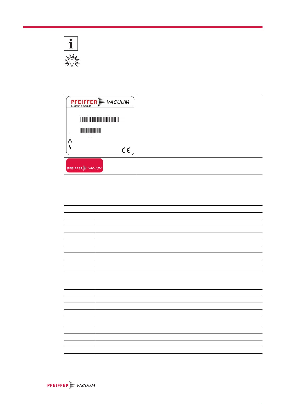
1.4.3 Stickers on the product
This section describes all the stickers on the product along with their meaning.
TC 400
Made in Germany
Input:
Output:
Ser.-No.: 12345678
Mod.:
M.-No.:
24 V / 48 V ± 10% 15 A
PM C01 800 A
0 - 48 V 12 A 0 - 1000 Hz
2019/01
Rating plate
The rating plate is located on the side of the electronic drive
unit.
warranty seal
Closure seal
The product is sealed ex-factory. Damaging or removing a clo-
sure seal results in loss of the warranty.
Tbl. 1: Stickers on the product
1.4.4 Abbreviations
Abbreviation Meaning in this document
AI/AO Analog Input/Analog Output
AIC Ampere Interrupting Capacity
DC Direct Current
DCU Display Control Unit from Pfeiffer Vacuum
DI/DO Digital Input/Digital Output
fRotation speed value of a vacuum pump (frequency, in rpm or Hz)
HPU Handheld Programming Unit, aid for controlling and monitoring parameters
IElectric amperage
LED Light Emitting Diode
[P:xxx] Electronic drive unit control parameters. Printed in bold as a three-digit number in
square brackets. Frequently displayed in conjunction with a short description
Example: [P:312] software version
PElectrical Power
PE Protective Earth
RElectrical Resistance
remote 26-pole D-Sub connecting socket on the turbopump electronic drive unit
RS-485 Standard for a physical interface for asynchronous serial data transmission (Recom-
mended Standard)
tTime
TC Electronic drive unit (Turbo Controller)
TMS Temperature Management System
UElectric voltage
Tbl. 2: Abbreviations used in this document
About this manual
8/48

2 Safety
2.1 General safety information
The following 4 risk levels and 1 information level are taken into account in this document.
DANGER
Immediately pending danger
Indicates an immediately pending danger that will result in death or serious injury if not observed.
►Instructions to avoid the danger situation
WARNING
Potential pending danger
Indicates a pending danger that could result in death or serious injury if not observed.
►Instructions to avoid the danger situation
CAUTION
Potential pending danger
Indicates a pending danger that could result in minor injuries if not observed.
►Instructions to avoid the danger situation
NOTICE
Danger of damage to property
Is used to highlight actions that are not associated with personal injury.
►Instructions to avoid damage to property
Notes, tips or examples indicate important information about the product or about this docu-
ment.
2.2 Safety instructions
All safety instructions in this document are based on the results of the risk assessment carried out in
accordance with Low Voltage Directive 2014/35/EU. Where applicable, all life cycle phases of the prod-
uct were taken into account.
Risks during installation
DANGER
Danger to life from electric shock
Power supply packs that are not specified or are not approved will lead to severe injury to death.
►Make sure that the power supply pack meets the requirements for double isolation between
mains input voltage and output voltage, in accordance with IEC 61010-1 IEC 60950-1 and
IEC 62368-1.
►Make sure that the power supply pack meets the requirements in accordance with IEC 61010-1
IEC 60950-1 and IEC 62368-1.
►Where possible, use original power supply packs or only power supply packs that correspond
with the applicable safety regulations.
Safety
9/48

DANGER
Danger to life from electric shock
When establishing the voltages that exceed the specified safety extra-low voltage (according to IEC
60449 and VDE 0100), the insulating measures will be destroyed. There is a danger to life from elec-
tric shock at the communication interfaces.
►Connect only suitable devices to the bus system.
WARNING
Risk of injury due to incorrect installation
Dangerous situations may arise from unsafe or incorrect installation.
►Do not carry out your own conversions or modifications on the unit.
►Ensure the integration into an Emergency Off safety circuit.
Risks in the event of malfunctions
WARNING
Risk of injury from parts moving after a power failure or troubleshooting
The "pumping station" function of the electronic drive unit will remain active after a power failure or if
errors occur that shut down the vacuum pump or the system. When power is restored or after ac-
knowledging a fault, the vacuum pump runs up automatically. There is a risk of injury to fingers and
hands if they enter the operating range of rotating parts.
►Always keep the mains connection freely accessible so you can disconnect it at any time.
►Remove present mating plugs or bridges from the electronic drive unit possibly before the mains
power returns, as these can cause an automatic run-up.
►Switch the pump off using the "Pumping station" function (parameter [P:010]).
2.3 Safety precautions
Duty to provide information on potential dangers
The product holder or user is obliged to make all operating personnel aware of dangers
posed by this product.
Every person who is involved in the installation, operation or maintenance of the product
must read, understand and adhere to the safety-related parts of this document.
Infringement of conformity due to modifications to the product
The Declaration of Conformity from the manufacturer is no longer valid if the operator
changes the original product or installs additional equipment.
●Following the installation into a system, the operator is required to check and re-evalu-
ate the conformity of the overall system in the context of the relevant European Direc-
tives, before commissioning that system.
General safety precautions when handling the product
►Use only power supply packs that comply with the applicable safety regulations.
►Observe all applicable safety and accident prevention regulations.
►Check that all safety measures are observed at regular intervals.
►Recommendation: Establish a secure connection to the earthed conductor (PE); protection class
III.
►Never disconnect plug connections during operation.
►Keep lines and cables away from hot surfaces (> 70 °C).
►Do not carry out your own conversions or modifications on the unit.
►Observe the unit protection class prior to installation or operation in other environments.
►Observe the protection class by ensuring the correct seating of the present sealing plugs.
►Disconnect the electronic drive unit only once everything has come to a complete standstill and
when the mains power supply of the turbopump is interrupted.
Safety
10/48

2.4 Limits of use of the product
Installation location weatherproof (internal space)
Air pressure 750 hPa to 1060 hPa
Installation altitude max. 5000 m
Rel. air humidity max. 80 %, at T ≤ 31 °C,
up to max. 50% at T ≤ 40°C
Protection class III
Excess voltage category II
Permissible protection degree IP54
Degree of contamination 2
Ambient temperature +5 °C to +40 °C
Tbl. 3: Permissible ambient conditions
Notes on ambient conditions
The specified permissible ambient temperatures apply to operation of the turbopump at
maximum permissible backing pressure or at maximum gas throughput, depending on the
cooling type. The turbopump is intrinsically safe thanks to redundant temperature monitor-
ing.
●The reduction in backing pressure or gas throughput permits operation of the turbo-
pump at higher ambient temperatures.
●If the maximum permissible operating temperature of the turbopump is exceeded, the
electronic drive unit first reduces the drive output and then switches it off where neces-
sary.
2.5 Proper use
●The electronic drive unit is used exclusively for the operation of Pfeiffer Vacuum turbopumps and
their accessories.
2.6 Foreseeable improper use
Improper use of the product invalidates all warranty and liability claims. Any use that is counter to the
purpose of the product, whether intentional or unintentional, is regarded as misuse, in particular:
●Connection to power supplies that do not comply with the provisions of IEC 61010 or IEC 60950
●Operation with excessively high irradiated heat output
●Use in areas with ionizing radiation
●Operation in explosion-hazard areas
●Use of accessories or spare parts that are not listed in these instructions
2.7 Functional safety
The TC 400 drive unit (electronic drive unit) executes the “Safe Limited Speed” safety function in ac-
cordance with EN 61800-5-2. In the event of excess rotation speed, the vacuum pump motor’s commu-
tation switches off and brings the drive into a safe state.
Summary of characteristic data for use in safety-related applications:
Characteristics in accordance with IEC 61508 and IEC 62061
Characteristic Safety Integrity Level PFH PFDav Proof Test Interval T
Value SIL CL 2 1.1 * 10-8 / h 1 * 10-3 20 a
Tbl. 4: Data for use in safety-related applications in accordance with IEC 61508 and
IEC 62061
Safety
11/48

Characteristics in accordance with EN ISO 13849-1
Characteristic Performance Level Category MTTFdAverage diagnostic coverage DC
Value PL d Cat. 3 high (135 a) Medium (90 % - < 99 %)
Tbl. 5: Data for use in safety-related applications in accordance with EN ISO 13849-1
●No proof test is required throughout the expected device lifetime of up to 20 years.
●If you calculate your safety application with the specified values for 20 years, you will need to de-
commission the safety controller and return it to the manufacturer after 20 years. You must not
perform a proof test.
Safety
12/48
3 Product description
3.1 Identifying the product
►To ensure clear identification of the product when communicating with Pfeiffer Vacuum, always
keep all of the information on the rating plate to hand.
►Learn about certifications through test seals on the product or at www.certipedia.com with compa-
ny ID no. 000021320.
3.2 Product features
The type TC 400 electronic drive unit is a permanent component of the turbopump. The purpose of the
electronic drive unit is to drive, monitor and control the entire turbopump.
Feature TC 400
Connection voltage TC 24 V DC ±10 % 48 V DC ±10 %
Connection panel Standard (RS-485) Standard (RS-485)
Turbopump HiPace 300, 400, 700, 800 300, 400, 700, 800
Tbl. 6: Features of the device variants
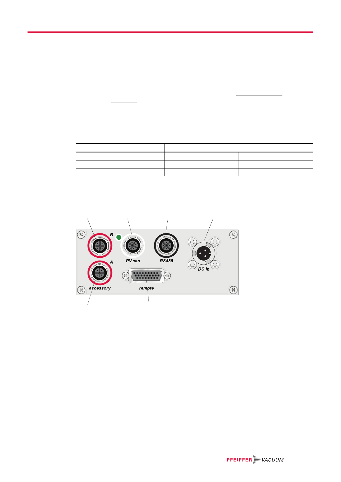
3.3 Function
1 2 3 4
56
Fig. 1: Standard panel TC 400
1 Connection "accessory B" 4 Connection "DC in"
2 “PV.can” service connection 5 "remote" connection
3 Connection "RS-485" 6 Connection "accessory A"
3.4 Scope of delivery
●TC 400
●Operating instructions
Product description
13/48

3.5 Connections
DC in1)
Housing connector with bayonet lock for the voltage supply between Pfeiffer Vac-
uum power supply packs and the TC electronic drive unit.
accessory
M12 socket with screw lock for the connection of Pfeiffer Vacuum accessories. The
use of a Y-distributor permits the double allocation of a connection.
PV.can
M12 socket with screw lock and LED for the connection of an integrated pressure
measurement and for Pfeiffer Vacuum service purposes.
remote
High-density D-sub socket with 26 pins for connection and configuration of a re-
mote control.
RS-485
M12 socket with screw lock for the connection of Pfeiffer Vacuum control panels or
PC. The use of a Y-distributor permits the integration into a bus system.
Device socket on the rear side of the electronic drive unit for the connection of the
turbopump.
Tbl. 7: Connection description of the electronic drive unit
1) "DC in" and "accessory" are described in the operating instructions of the turbopump.
Product description
14/48

4 Installation
4.1 Connection diagram
DANGER
Danger to life from electric shock
Power supply packs that are not specified or are not approved will lead to severe injury to death.
►Make sure that the power supply pack meets the requirements for double isolation between
mains input voltage and output voltage, in accordance with IEC 61010-1 IEC 60950-1 and
IEC 62368-1.
►Make sure that the power supply pack meets the requirements in accordance with IEC 61010-1
IEC 60950-1 and IEC 62368-1.
►Where possible, use original power supply packs or only power supply packs that correspond
with the applicable safety regulations.
DANGER
Danger to life from electric shock
When establishing the voltages that exceed the specified safety extra-low voltage (according to IEC
60449 and VDE 0100), the insulating measures will be destroyed. There is a danger to life from elec-
tric shock at the communication interfaces.
►Connect only suitable devices to the bus system.
WARNING
Risk of injury due to incorrect installation
Dangerous situations may arise from unsafe or incorrect installation.
►Do not carry out your own conversions or modifications on the unit.
►Ensure the integration into an Emergency Off safety circuit.
Contact load for the accessory connections to "accessory"
1. Note the maximum contact load of 200 mA per connection.
2. However, do not exceed the total sum of the load of all connections of 450 mA.
Potential-free connections
●All inputs and outputs of the "remote” connections, "RS-485" and "PV.can" are galvani-
cally separated from +UB .
●The contacts of relays 1, 2 and 3 are potential-free.
Installation
15/48

4 1
5
23
32
5
1 4
13
4
2
A C
B
1
9
10
18
19
26
1
2
3
4
5
1
2
3
4
5
1
2
3
4
5
A
B
C
1
2
3
4
5
1
2
3
4
5
6
7
8
9
10
11
12
13
14
15
16
17
18
19
20
21
22
23
24
25
26
Accessory BAccessory A
Remote
DC in
UB= + 24 / 48 V DC ± 10 %
PV.can
RS485
galvanically
separated from UB
in this area
n.c.
24 V DC
Acc. B1
FE
Acc. B2
+ UB
FE
GND
n.c.
24 V DC
Acc. A1
FE
Acc. A2
+ 24 V DC* out
DI Motor Pump
DI Pumping Station
DI Standby
DI1
DI2
DO1
DO2
DI3
AI+ 0-10 V DC
AI- GND
DI Error Ackn.
DI Remote Priority
Relay 1
Relay 1
Relay 1
Relay 2
Relay 2
Relay 2
Relay 3
Relay 3
AO1 / 0-10 V
DO Remote Prio Active
RS485 D-
RS485 D+
GND*
24 V DC* out
RS 485 D +
RS 485 D -
n.c.
GND*
Fig. 2: Connection diagram for the electronic drive unit. Example: external circuit for "re-
mote"
4.2 "remote" connection
The 26-pin D-sub connection with the "remote" designation offers the possibility to operate the electron-
ic drive unit via remote control. The accessible individual functions are mapped to "PLC levels". The fol-
lowing specifications are the factory settings for the electronic drive unit. They can be configured with
the Pfeiffer Vacuum parameter set.
Installation
16/48
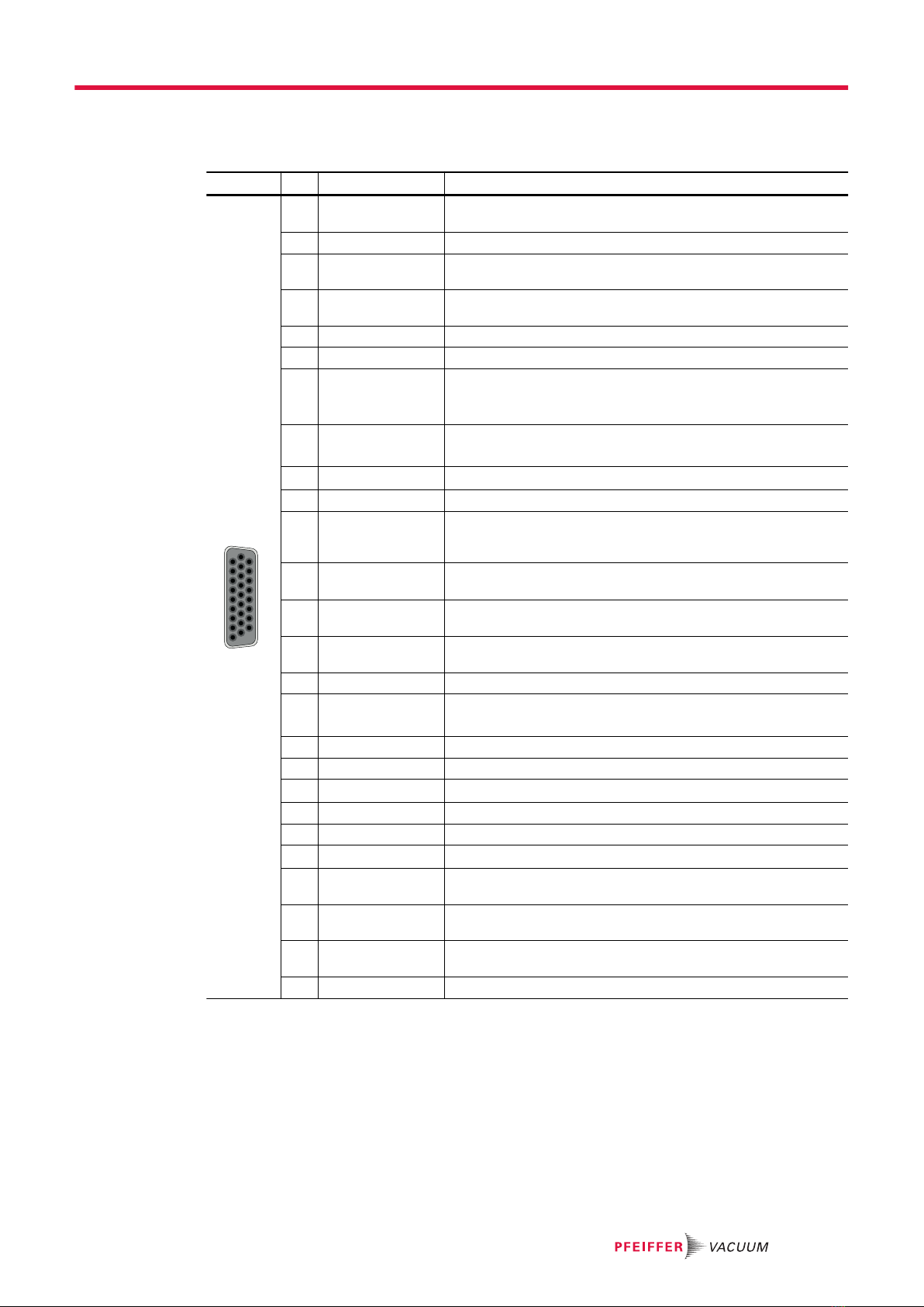
►Remove the remote plug from the TC 400 and connect a remote control.
►Utilize the screened plug and cable.
Pin Assignment Description, factory setting
19
10
18
1926
1 +24 V DC* output
(V+)
Reference voltage for all digital inputs and outputs
2 DI1 Enable venting (open: off, V+: on)
3 DI motor vacuum
pump
Drive motor (open: off; V+: on)
4 DI pumping sta-
tion
open: off; V+: on and error acknowledgment
5 DI standby Standby rotation speed (open: off, V+: on)
6 DI2 Heater (open: off, V+: on)
7 AI+ rotation
speed setting
mode
Setpoint in rotation speed setting mode;
2 - 10 V DC corresponds to 20 - 100% of the nominal rotation
speed
8 DO1 Speed-control switchpoint reached;
GND: no, V+: yes (Imax = 50 mA/24 V)
9 DO2 GND: error, V+: no error (lmax = 50 mA/24 V)
10 DI3 Sealing gas (open: off, V+: on)
11 AI rotation speed
setting mode
GND
Setpoint in rotation speed setting mode; GND
12 AO1 Actual speed; 0 to 10 V DC corresponds to 0 to 100%: RL
> 10 kΩ
13 DI error acknowl-
edgement
Error acknowledgement: V+ pulse (min. 500 ms)
14 DI remote priority Operation via "remote" interface (open: off, V+: set and takes
priority over other digital inputs)
15 Relay 1 Connection with pin 16, if relay 1 inactive
16 Relay 1 Rotation speed switchpoint reached;
Relay contact 1 (Umax = 50 V DC; Imax = 1 A)
17 Relay 1 Connection with pin 16, if relay 1 active
18 Relay 2 Connection with pin 19, if relay 2 inactive
19 Relay 2 No error; relay contact 2 (Umax = 50 V DC; Imax = 1 A)
20 Relay 2 Connection with pin 19, if relay 2 active
21 Relay 3 Connection with pin 22, if relay 3 inactive
22 Relay 3 Warning; relay contact 3 (Umax = 50 V DC; Imax = 1 A)
23 DO remote priori-
ty
GND: off, V+: remote priority active
24 RS-485 D+ in accordance with the specification and Pfeiffer Vacuum pro-
tocol
25 RS-485 D- in accordance with the specification and Pfeiffer Vacuum pro-
tocol
26 Ground (GND*) Reference mass for all digital inputs and outputs
Tbl. 8: Terminal layout of 26-pin "remote" connection
4.2.1 Voltage supply
+24 V DC* output/pin 1
A connection with +24 V DC to pin 1 (active high) activates inputs 2 to 6, as well as the connections to
pins 10, 13 and 14. Alternatively, they can be activated via an external PLC. "PLC High level" activates
and "PLC Low level" deactivates the functions.
●PLC High level: +13 V to +33 V
●PLC Low level: -33 V to +7 V
Installation
17/48

●Ri: 7 kΩ
●lmax < 210 mA (with RS-485, where present)
4.2.2 Inputs
The digital inputs at the "remote" connection are used to switch various electronic drive unit functions.
Inputs DI1 to DI2 are assigned functions in the factory. You can configure them via the RS-485 interface
and the Pfeiffer Vacuum parameter set.
DI1 (release venting)/pin 2
V+: Enable venting (venting as per venting mode)
open: Venting blocked (no venting occurs)
DI motor vacuum pump/pin 3
The turbopump starts up with activation of pin 4 (pumping station) and successful self-testing of the
electronic drive unit. The turbopump can be switched off and switched on again during operation with
the pumping station still activated. This will not initiate a venting action.
V+: Turbo pump motor on
open: Turbo pump motor off
DI pumping station/pin 4
Control of connected pumping station components (e.g. backing pump, venting valve, air cooling) and
start-up of the turbopump with simultaneously activated pin 3 (motor). Any pending error messages are
reset by eliminating the cause.
V+: Error acknowledgement and pumping station on
open: Pumping station off
DI standby/pin 5
In standby mode, the turbopump operates at a specified rotor speed < nominal rotation speed. The fac-
tory setting and recommended operation is 66.7 % of the nominal rotation speed.
V+: Standby activated
open: Standby off, operation at nominal rotation speed
DI2 (heater)/pin 6
V+: Heater on
open: Heater off
DI3 (sealing gas)/pin 10
V+: Sealing gas valve open
open: Sealing gas valve closed
DI error acknowledgment/pin 13
V+: Pending error messages reset when cause has been eliminated with a pulse of min. 500 ms
duration
open: Inactive
DI remote priority/pin 14
V+: The "remote" connection has control priority over all other digital inputs.
open: Remote priority inactive
AI rotation speed setting mode/pin 7 and pin 11
The analog input serves as a rotation speed setpoint for the turbopump. An input signal of 2 to 10 V
between Al+ (pin 7) and GND (pin 11) corresponds to a rotation speed within the range of 20 to 100 %
of the nominal rotation speed. If the input is open or signals are below 2 V, the turbopump accelerates
to the nominal rotation speed.
Installation
18/48

100
20
2 10
f(%)
U(V)
Fig. 3: Rotation speed setting mode pin 7 and pin 11
4.2.3 Outputs
The digital outputs at the "remote" connection have a maximum load limit of 24 V/50 mA per output.
You can configure all outputs listed below with the Pfeiffer Vacuum parameter set via the RS-485 inter-
face (description relates to factory settings).
DO1 (rotation speed switch point reached)/pin 8
Active high: After reaching the rotation speed switch point. Rotation speed switch point 1 has a factory
setting of 80% of the nominal rotation speed. This can be used for a “Ready for operation” message, for
example.
DO2 (no error)/pin 9
When the supply voltage has been connected, digital output DO2 permanently outputs 24 V DC, which
means “no error”. Active low: in case of error (group error message).
DO remote priority active/pin 23
Active high: The "remote" connection takes priority over all other potentially connected control units
(e.g. RS-485). Active low ignores the "remote" connection.
AO1 analog output 0 to 10 V DC/pin 12
You can pick off a speed-proportional voltage (0 to 10 V DC, equals 0 to 100% × fNominal) at the analog
output (load R ≥ 10 kΩ). You can assign additional functions (optionally current/power) to the analog
output via DCU, HPU or PC.
4.2.4 Relay contacts (invertible)
Relay 1/pins 15, 16 and 17
The contact between pin 16 and pin 15 is closed when the rotation speed drops below the switchpoint;
relay 1 is inactive. The contact between pin 16 and pin 17 is closed when the speed reaches the rota-
tion speed switchpoint; relay 1 is active.
Relay 2/pins 18, 19 and 20
The contact between pin 19 and pin 18 is closed when an error is pending; relay 2 is inactive. The con-
tact between pin 19 and pin 20 is closed in case of trouble-free operation; relay 2 is active.
Relay 3/pins 21 and 22
The contact between pin 21 and pin 22 is closed in case of inactive warning messages; relay 3 is inac-
tive. The contact between pin 21 and pin 22 is open when warnings are pending; relay 3 is active.
4.2.5 RS-485
Pin 24 and pin 25
You can connect a Pfeiffer Vacuum display and control unit (DCU or HPU) or an external PC via pin 24
and pin 25 at the "remote” connection of the electronic drive unit.
Installation
19/48

5 Interfaces
5.1 Interface RS-485
The interface with the designation “RS-485” is intended for the connection of a Pfeiffer Vacuum display
and control unit (DCU or HPU) or an external computer. The connections are galvanically safe and are
isolated from the maximum supply voltage of the electronic drive unit. The electrical connections are op-
tically decoupled internally.
Designation Value
Serial interface RS-485
Baudrate 9600 Baud
Data word length 8 bit
Parity none (no parity)
Start bits 1
Stop bits 1
Tbl. 9: Features of the RS-485 interface
Pin Assignment
1 2
34
5
1 RS-485 D+
2 +24 V output, ≤ 210 mA loading capacity
3 GND
4 RS-485 D-
5 not connected
Tbl. 10: Terminal layout of the RS-485 connecting socket M12
5.1.1 Connection options
DCU 002
DCU 310 / 400
TC 400 / TM 700
HPU 001
RS-485
USB/RS-485-converter
Fig. 4: Connection options via interface RS-485
Connecting Pfeiffer Vacuum display and control panels or PC
At interface RS-485, one external control panel can be connected in each case.
1. Use the respective connection cable supplied with the control panel or from the range of accesso-
ries.
2. Use the option to connect a PC via the USB/RS-485 converter.
Interfaces
20/48
Other manuals for TC 400
1
Table of contents
Other Pfeiffer Vacuum Portable Generator manuals


