412 · Technischer Anhang/Technical appendix
blueglobe®EMV – Montageanleitung
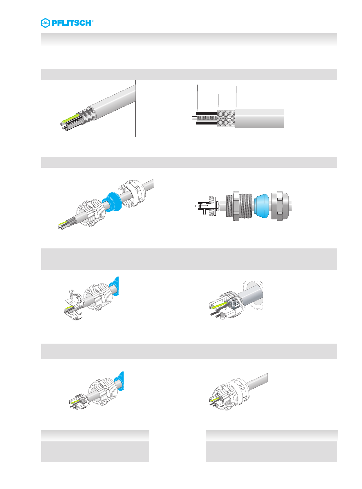
blueglobe®EMC – Assembly Instruction
➞
A
➞
B
Schritt 1 der Montage
Step 1 of installation
Leitung abmanteln, Schirme (A + B) freilegen.
Dismantle wire and bare screens (A + B)
Schritt 2 der Montage
Step 2 of installation
Druckschraube mit Dichteinsatz (blueglobe®– C) und Verschraubungskörper (D) auf den Kabelmantel auffädeln
Install screen connection plates that one of the inner screens is left and the other is right of the central screw (valid for cables with 2 selective screens)
➞
➞
➞
➞
> 25
10
➞
D
➞
E
➞
E
➞
F
➞
D
➞
D
➞
➞
➞
➞
C
➞
C
Kontaktierung der Selektivschirme
Contacting selective screens
Kontaktierung des Gesamtschirms
Contacting outer screens
Schritt 3 der Montage
Step 3 of installation
Schirmanschlussbleche (E) aufschieben, so dass (bei Kabeln mit 2 Selektivschirmen) einer der Innenschirme links, der andere rechts der mittigen
Schraube (F) zu liegen kommt; Anzugsdrehmomente siehe Tabelle 1
Install screen connection plates (E) that one of the inner screens is left and the other is right of the central screw (F) (valid for cables with 2 selective screens);
tightening torques see table 1
➞
➞
Innenschirm 1
Inner screen 1
Innenschirm 2
Inner screen 2
Schritt 4 der Montage
Step 4 of installation
Die Leitung unter leichtem Drehen im Uhrzeigersinn so weit zurückziehen, bis das Schirmanschlusselement (E) in den Verschraubungskörper (D) eintaucht.
Druckschraube (C) anziehen; Anzugmomente siehe Tabelle 2
Pull back wire (E) while slightly turning clockwise until screen connection unit is fully fixed in double nipple (D). Fix pressure screw (C); tightening torques see table 2
➞
➞
A
B
Tabelle 1
Table 1
Artikel Schraube (F) Nenndrehmoment/Nm
Article Screw (F) Nominal torque/Nm
bgSS 220ms M2 0,7
bgSS 225ms M3 0,8
bgSS 232ms M3 0,8
Tabelle 2
Table 2
Artikel Druckschraube (C) Nenndrehmoment/Nm
Article Pressure screw (C) Nominal torque/Nm
bgSS 220ms M20 max. 10
bgSS 225ms M25 max. 15
bgSS 232ms M32 max. 15


