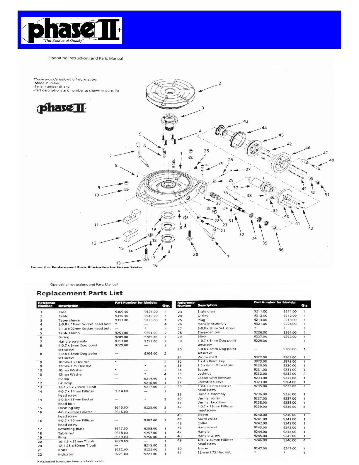
OperatingInstructions&PartsManual
HorizontalRotaryTables
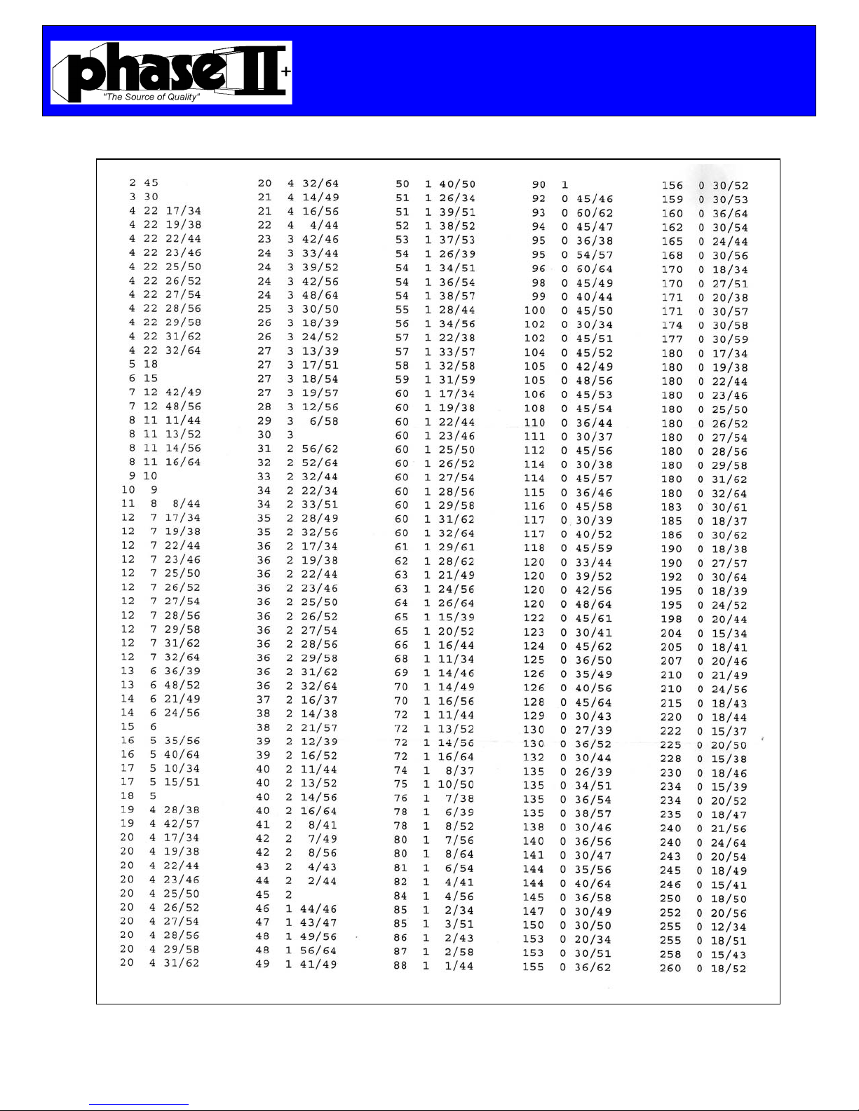
DividingPlates
Pg. 2
Operating Instructions & Parts Manuals
Please read and save these instructions. Read carefully before attempting to assemble, install, operate or maintain the product
described. Protect yourself and others by observing all safety information. Failure to comply with instructions could result in personal
injury and or property damage! Retain instructions for future reference.
Description
ThePhaseIIhorizontalrotarytablesareusedfor
indexing,circularcutting,anglesetting,boringand
spotfacingoperations.Themeehanitecastiron
tableisprecisionmachinedandisprovidedwitha
MorseTapercenterhole.Thetableisgraduated
witha360scale.Amicrocollargraduatedtoone
minutewithatensecondaccuracyvernierscaleis
provided.Rotarytablefeaturesincludelock‐down
handlesandcrankdisengagementmechanism.
Wormgearandcenterholetaperarehardened
andground.Thedividingplatesaccessoryallows
theoperatortoaccuratelydividethe360rotation
oftheclampingsurfaceintodivisionsof2through
66,andalldivisiblesof2,3and5from67‐132.
Unpacking
Checkforshippingdamage.Ifdamagehasoccurred,a
claimmustbefiledwithcarrierimmediately.Checkfor
completeness.Immediatelyreportmissingpartsto
dealer.Carefullyremovetablefromcrate.
Important:Thetoolhasbeencoatedwithprotective
coating.Inordertoensureproperfitandoperationthe
coatingmustberemoved,removecoatingwithmild
solventssuchasmineralspiritsandasoftcloth.
Nonflammablesolventsarerecommended.After
cleaning,coverallexposedsurfaceswithalightcoating
ofoil.Besuretolubricatetableasdescribedin
"Maintenance"
Caution:Neverusehighlyvolatilesolvents.
Avoidgettingcleaningsolutiononpaint,asit
maytendtodeterioratethesefinishes.Use
soapandwateronpaintedcomponents.
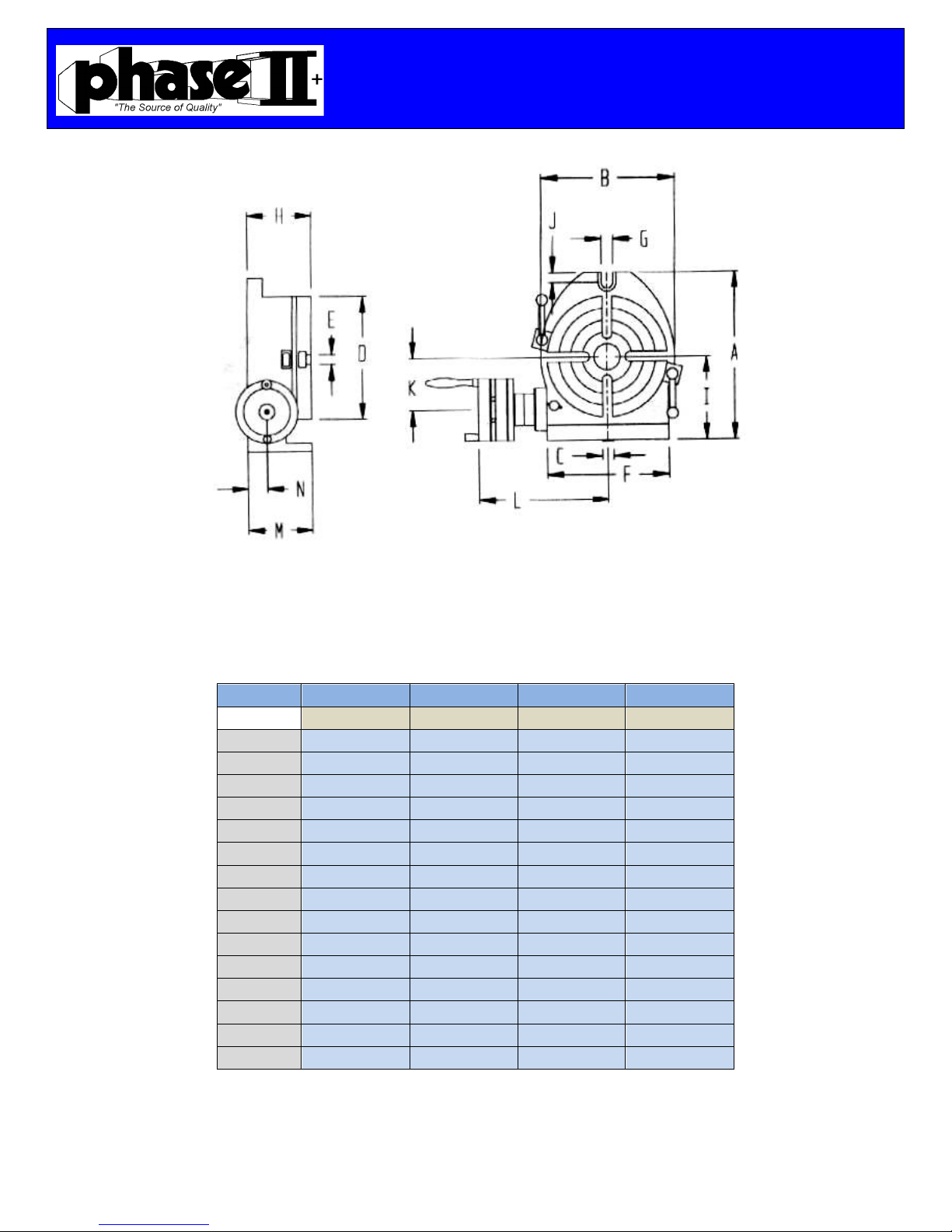
Specifications
DividingPlatesAccessory
Possibledivisionsof
Onerotation:...................2thru66,andall
...............................................divisiblesof2,3,and5
...............................................from67‐132
Accuracy MaximumT.I.P.
Flatnessofclampingsurface.............................0.0006”
Parallelismofclamping
Surfacetobase.......................................................0.0008”
Squarnessofclampingsurface
toangleface............................................................0.0004"
Squarenessofclampingsurface
tocenterslot...........................................................0.0008"
Concentricityofcenterbore..............................0.0008"
Maximumspacingerror:
6”&8”.....................................1minute,20seconds
10”,12”&16”.........................45seconds
GeneralSafetyInformation
1. Readandfollowalloperatinginstructionbeforeoperating
rotarytable.
2. Understandandobeyallsafetyinstructionssuppliedwithmill
orothermachinesonwhichtherotarytableisused.
3. Alwayssecurerotarytabletoworksurfaceorothermachine.
4. Alwayssecureworkpiecetorotarytableclampingsurfaceif
used.
5. Alwayssecurefaceplatetorotarytableclampingsurfaceif
used.
6. Alwayssecurerotarytableclampingsurfacewithlock‐down
handleswhenpossible.
7. Maintainandlubricatetoolproperly.
Installation
1. Mountrotarytablesecurelytomachineworksurface.
2. Useslotsprovidedontableandbesurethattableis
rigidlyandsafelysecured.
3. Tablecanonlybemountedhorizontallywithslots
provided.
Lubrication
Keeprotarytablecleanofdirtorchips.
Beforeputtingintouse,fillbasecavitywith
oilusingtheoilzertsonbase,tableandoil
plug(RefNo.11).UnscrewoilPlugpriorto
lubrication.Beforeeveryshiftofoperationfill
adequateoilthroughoilzertsandoilplug.
LUBRICATEWITHLIGHTDUTY
HYDRAULICFLUIDORSPINDLEOIL.Table
shouldbefilledwithoiluntilititvisiblein
thesightglass,donotoverfill.
Frequentlycheckoillevelusingsightglass
(Ref.No.8)Donotuserotarytablewithout
adequateoil.