FAR RAC 211 User manual

EAC
RAC 211
PT
RUS
I
GB
F
E
D
PL
RAC 211
- ISTRUZIONI ORIGINALI
RIVETTATRICE OLEOPNEUMATICA
PER RIVETTI Ø 2,4 ÷ Ø 4,8
*
(
*
Ø 4,8 SOLO ALLUMINIO)
ISTRUZIONI D’USO - PARTI DI RICAMBIO
- TRANSLATION OF ORIGINAL INSTRUCTIONS
HYDROPNEUMATIC RIVETING TOOL
FOR RIVETS Ø 2,4 ÷ Ø 4,8
*
(
*
Ø 4,8 ALUMINIUM ONLY)
INSTRUCTIONS FOR USE - SPARE PARTS
- TRADUCTION DES
INSTRUCTIONS ORIGINALES
OUTIL À RIVETER OLÉOPNEUMATIQUE
POUR RIVETS Ø 2,4 ÷ Ø 4,8
*
(
*
Ø 4,8 ALUMINIUM SEULEMENT)
MODE D’EMPLOI - PIÈCES DÉTACHÉES
- ÜBERSETZUNG VON
ORIGINALANLEITUNGEN
PNEUMATISCH-HYDRAULISCHES WERKZEUG
FÜR NIETE 2,4 ÷ 4,8 Ø
*
(
*
4,8 Ø
NUR ALUMINIUM
)
BEDIENUNGSANLEITUNG - ERSATZTEILE
- TRADUCCION DE LAS
ISTRUCCIONES ORIGINALES
REMACHADORA OLEONEUMATICA
PARA REMACHES Ø 2,4 ÷ Ø 4,8
*
(
*
Ø 4,8 SOLO EN ALUMINIO)
INSTRUCCIONES DE USO - PIEZAS DE REPUESTO
- TŁUMACZENIE ORYGINALNEJ INSTRUKCJI
NITOWNICA PNEUMATYCZNO-HYDRAULICZNA
DO NITÓW
Ø
2,4-4,8 MM
*
(
*Ø
4,8 MM TYLKO ALUMINIUM)
INSTRUKCJA OBSŁUGI CZĘŚCI ZAMIENNE
-
ГИДРОПНЕВМАТИЧЕСКИЙ ИНСТРУМЕНТ
ДЛЯ ЗАКЛЕПОК Ø
2,4-4,8
*
(
*Ø
4,8
ТОЛЬКО ИЗ АЛЛЮМИНИЯ )
•
ДАТА ПРОИЗВОДСТВА УКАЗАНА В «ТЕХНИЧЕСКОМ ПАСПОРТЕ»
- TRADUÇÃO DAS INSTRUÇÕES ORIGINAIS
REBITADORA OLEOPNEUMÁTICA
PARA REBITES Ø 2,4 ÷ Ø 4,8
*
(
*
Ø 4,8 SÓ ALUMÍNIO)
INSTRUÇÕES DE UTILIZAÇÃO – PEÇAS SOBRESSALENTES

RAC 211
I
F
E
GB
D
La sottoscritta Far S.r.l., con sede in Quarto Inferiore (BO) alla via Giovanni XXIII n° 2,
DICHIARA
sotto la propria esclusiva responsabilità che la rivettatrice
Modello: RAC 211 - Rivettatrice oleopneumatica Utilizzo: per rivetti diam. 2,4 - 4,8 (4,8 solo alluminio), numero di serie:
vedi retro copertina, alla quale questa dichiarazione si riferisce è conforme ai requisiti essenziali di sicurezza previsti dal
D. Lgs. 17/2010 di recepimento della Direttiva Macchine 2006/42/CE e successive modificazioni ed integrazioni, e CU TR
010/2011. La persona autorizzata a costituire il fascicolo tecnico risponde al nome di Massimo Generali, presso la Far
S.r.l., con sede in Quarto Inferiore (BO) alla via Giovanni XXIII n° 2
The undersigned Far S.r.l., having its office in Quarto Inferiore (BO), Via Giovanni XXIII No. 2, herewith
DECLARES
on its sole responsability that the riveting machine
Type: RAC 211 - Hydropneumatic tool Application: for rivets diam. 2,4 - 4,8 (4,8 aluminium only), serial number: see back cover,
which is the object of this declaration complies with the basic safety requirements estabilished in the law decree Leg. D. 17/2010
of the Machinery Directive 2006/42/CE acknowledge and subsequent amendments and integrations
and CU TR 010/2011
.
The person who is authorized to create the technical brochure is Massimo Generali, c/o Far S.r.l., head office in Quarto Inferiore
(BO), via Giovanni XXIII n. 2.
La société Far S.r.l. soussignée avec siège à Quarto Inferiore (BO), Via Giovanni XXIII n° 2,
DECLARE
sous sa seule responsabilité que la riveteuse
Modèle: RAC 211 - Pistolet oléopneumatique Utilisation: pour rivets diam. 2,4 - 4,8 (4,8 alu seulement), numéro de série: voir
la dos couverture, à laquelle cette déclaration se rapporte est conforme aux conditions essentielles de sécurité requises par la
loi 17/2010 d’acceptation de la Directive Machines 2006/42/CE et modifications et intégrations successives
et CU TR 010/2011.
La personne autorisée à constituer le dossier technique est Massimo Generali chez FAR S.r.l., avec siège à Quarto Inferiore (BO)
– Via Giovanni XXIII. n.2
Die Unterzeichnete, Fa. Far S.r.l., mit Sitz in Quarto Inferiore (BO), Via Giovanni XXIII Nr. 2,
ERKLÄRT
hiermit auf ihre alleinige Verantwortung, daß die
Nietmaschine Typ: RAC 211 - Hydraulisch-pneumatisches Nietwerkzeug Anwendung: für Blindniete mit Durchmesser 2,4 – 4,8 (4,8
nur für Alu), seriennummer siehe Rückseite, auf das sich diese Erklärung bezieht, den wesentlichen Sicherheitsanforderungen des
Gesetzesdekrets17/2010vonUmsetzungderMaschinenrichtlinie2006/42/CEunddennachfolgendenÄnderungenundAnfügungen
entspricht
und CU TR 010/2011.
Der Berechtigte zur Bild
Der Berechtigte zur Bildung der technische Broschüre ist Massimo Generali, bei der Firma Far S.r.l., mit
Sitz in Quarto Inferiore (BO), via Giovanni XXIII Nr. 2.
La firmataria Far S.r.l., domiciliada en Quarto Inferiore (BO) en via Giovanni XXIII n° 2,
DECLARA
bajo su exclusiva responsabilidad que la remachadora
Modelo: RAC 211 - Remachadora oleoneumática Empleo: para remaches diam. 2,4 – 4,8 (4,8 este último sólo aluminio), número de
serie: ver la contratapa, a la cual la presente declaración se refiere corresponde a los requisitos esenciales de seguridad previstos por
el D.Lay 17/2010 de recepción de la Directiva Maquinas 2006/42/CE y sucesivas modificaciones e integraciones
y CU TR 010/2011.
La persona autirizada a constituir el fasciculo tecnico es Massimo Generali, cerca FAR S.r.l., con sede a Quarto Inferiore (BO) – Via
Giovanni XXIII n.2.

RAC 211
PL
RUS
PT
Far S.r.l. - Massimo Generali
(Presidente del Consiglio di Amministrazione)
(Chairman of the Board of Directors)
(Président du Conseil d’Administration)
(Vorsitzender des Verwaltungsrates)
(Presidente del Consejo de Administración)
(Prezes Zarzadu)
(Председатель Административного Совета)
(Presidente do Conselho de Administração)
.............................................
A abaixo-assinada Far S.r.l., com sede em Quarto Inferior (BO) na via Giovanni XXIII n° 2,
DECLARA
sob sua exclusiva responsabilidade que a máquina de rebitar Modelo: RAC 211 - Máquina de rebitar óleo-pneumática Uso: para rebites diâm.
2,4 - 4,8 (4,8 apenas alumínio), número de série: ver parte traseira da capa à qual esta declaração é referida, está em conformidade com os
requisitos essenciais de segurança prescritos pelo D.Leg. 17/2010 de recepção da Diretiva de Máquinas 2006/42/CE e sucessivas modificações
e integrações e CU TR 010/2011.
Apessoaautorizadaaconstituirofascículotécnicoé
MassimoGenerali
,naFar S.r.l., comsedeemQuartoInferiore(BO)naviaGiovanniXXIIIn° 2.
Niżej podpisana firma Far S.r.l., z siedzibą w Quarto Inferiore (BO), via Giovanni XXIII nr 2,
OŚWIADCZA
na własną i wyłączną odpowiedzialność, że nitownica
Model: RAC 211 – Nitownica oleopneumatyczna Zastosowanie: do nitów o śred. 2,4 - 4,8 (4,8 tylko aluminium), numer seryjny patrz tylna
okładka,doktórejodnosisięniniejszadeklaracja,jestzgodnazwymogamibezpieczeństwaprzewidzianymiprzezD.Lgs.17/2010implementujący
Dyrektywę Maszynową 2006/42/WE wraz z późniejszymi zmianami i uzupełnieniami i CU TR 010/2011.
Osoba upoważniona do utworzenia dokumentacji technicznej to Massimo Generali z firmy Far S.r.l. mającej siedzibę w Quarto Inferiore (BO),
via Giovanni XXIII nr 2
Нижеподписавшeeся Far S.r.l., с местонахождением в Quarto Inferiore (BO) ул. Giovanni XXIII, 2,
под свою исключительную ответственность, что заклепочник модели: RAC 211 - Масляно-пневматический заклепочный инструмент
Использование: для заклепок диам. 2,4 ÷ 4,8 (4,8 только алюминиевые), серийный номер: см. на внутренней стороне задней обложки,
к которому это заявление относится, соблюдает основные требования безопасности, предусмотренные Проектом закона 17/2010 по
трансформациидирективы по машинному оборудованию 2006/42/EC,споследующимимодификациями идополнениями и ТР ТС010/2011.
Уполномоченным лицом для создания технической документации является господин (Massimo Generali), в головном офисе компании Far
S.r.l., который расположен по адресу: Италия, Куарто Инфериоре (Болонья), ул Джованни XXIII, д. 2.
Quarto Inferiore, 01-03-2019


RAC 211
PARTI DI RICAMBIO .............................................42
SPARE PARTS.......................................................43
PIECES DETACHEES .............................................44
ERSATZTEILE........................................................45
PIEZAS DE REPUESTO..........................................46
CZĘŚCI ZAMIENNE ....................................................47
....................................................48
PEÇAS SOBRESSALENTES...................................49
NOTE GENERALI E CAMPO DI APPLICAZIONE.......6
GENERAL NOTES AND USE....................................6
CARACTERISTIQUES ET EMPLOI ...........................6
ALLGEMEINES UND HANDHABUNG ......................6
NOTAS GENERALES Y AMBITO DE APLICACION ...6
UWAGI OGÓLNE I ZAKRES ZASTOSOWANIA NITOWNICY ...7
..................7
NOTAS GERAIS E CAMPO DE APLICAÇÃO ............7
I
F
E
PL
RUS
GB
D
ISTRUZIONI D’USO...............................................10
INSTRUCTIONS FOR USE.....................................14
MODE D’EMPLOI..................................................18
BEDIENUNGSANLEITUNG.....................................22
INSTRUCCIONES DE USO.....................................26
INSTRUKCJA OBSŁUGI...............................................30
A .......................34
INSTRUÇÕES DE USO ..........................................38
RISOLUZIONE DEI PROBLEMI .............................52
TROUBLE SHOOTING ...........................................53
DÉPANNAGE .........................................................54
FEHLERBEHEBUNG ..............................................55
RESOLUCIÓN DE PROBLEMAS ............................56
ROZWIĄZYWANIE PROBLEMÓW.................................57
........................................58
SOLUÇÃO DE PROBLEMAS ..................................59
ACCESSORI ..........................................................51
ACCESSORIES ......................................................51
ACCESSOIRES ......................................................51
ZUBEHÖR..............................................................51
ACCESORIOS........................................................51
AKCESORIA.........................................................51
................................................51
ACCESORIOS........................................................51
PT
II
II
FF
FF
EE
EE
PL PL
PL PL
RUS RUS
RUS RUS
GB GB
GB GB
DD
DD
PT PT
PT PT

6
RAC 211
75036124 - RAC 211 – rev 00 - ( 04-2019 )
GB
I
E
D
F
CARACTERISTIQUES ET EMPLOI
L’outil de pose ne peut être utilisé que pour rivets de ø 2,4 à 4,8 mm.
Le ø 4,8 mm pour rivets en aluminium.
Le système oléopneumatique de l’outil RAC 211 permet d’obtenir un puissance supérieure par rapport au système
pneumatique traditionnel. Cela signifie une réduction des problemes provoques par l’usure des composants, donc, une
plus grande longevité. Les solutions techniques adoptées réduisent les dimensions et le poids du pistolet en la rendant
très maniable. Les risques de fuites du système oléodynamique sont éliminés par l’utilisation de joints à haute résistance.
ALLGEMEINES UND ANWENDUNGSBEREICH
Das Werkzeug soll nur für Niete von 2.4 ÷ 4,8 mm verwendet werden.
4,8 Durchmesser nur in Aluminium.
DasÖlpneumatischeSystemder
RAC211
gewährleistetmehrKraftalsdaspneumatischeSystemandererModelle..Diesbedeutet
einedrastische Herabsetzung derProbleme,die aufdenVerschleißder Komponenten zurückzuführensindund einem sichdaraus
ergebenden Anstieg der Zuverlässigkeit und Haltbarkeit. Die angewandten technischen Lösungen setzen die Dimensionen und
das Gewicht der Maschine herab und machen das Nietwerkzeug
RAC 211
absolut handlich. Die Möglichkeiten des Auslaufens
von Öl aus dem öldynamischen System werden durch die Verwendung von undurchlässigen Dichtungen verhindert, die dieses
Problem eliminieren.
NOTAS GENERALES Y AMBITO DE APLICACION
El equipo se utiliza sólo para remaches de diámetro incluido entre ø 2,4 y 4,8 mm.
El diámetro ø 4,8 mm se utiliza sólo para remaches de aluminio.
Graciasalsistemaoleoneumático,laremachadoraRAC211brindaunapotenciamayorrespectoalastradicionalesremachadoras
neumáticas. Esto significa una notable reducción de los problemas causados por el desgaste de los componentes y como
consecuencia un aumento de la fiabilidad y duración. Las soluciones técnicas adoptadas reducen las dimensiones y el peso
de la máquina rindiendo la remachadora RAC 211 absolutamente maniobrable. Las posibilidades de perdida por et sistema
oleodinámico son eliminadas con el uso de retenes que eliminan este problema.
NOTE GENERALI E CAMPO DI APPLICAZIONE
L’uso dell’utensile è finalizzato esclusivamente all’utilizzo di rivetti a strappo di diametro compreso tra ø 2,4 e 4,8 mm.
Il diametro ø 4,8 mm può essere impiegato solo per rivetti in alluminio.
Il sistema oleopneumatico utilizzato dalla rivettatrice RAC 211 fornisce una maggior potenza rispetto al tradizionale
sistema pneumatico su cui si basano altri modelli di rivettatrici. Ciò significa una drastica riduzione dei problemi dovuti
all’usura dei componenti con conseguente aumento di affidabilità e durata. Le soluzioni tecniche adottate riducono le
dimensioni e il peso della macchina rendendo la rivettatrice RAC 211 assolutamente maneggevole. La possibilità di
perdite dal sistema oleo
dinamico s
ono precluse dall’impiego di guarnizioni a tenuta che eliminano questo problema.
GENERAL NOTES AND USE
The tool must be used for rivets diam. 2,4 ÷ 4,8 mm only.
Diam 4,8 mm only in aluminium.
The RAC 211 oil pneumatic system assures more power than the pneumatic system used for other models. That means a
reduction in the problems due to the wear and tear of the components, therefore, there will be an increase in reliability. The
technicai solutions adopted reduce the dimensions and the weight of the tooi which, for these reasons, make it very handy.
The possibilities of leakage from the oil-dynamic system, are eliminated by some sealed gaskets, which solve this problem.

7
RAC 211
75036124 - RAC 211 – rev 00 - ( 04-2019 )
PL
UWAGI OGÓLNE ORAZ ZAKRES ZASTOSOWANIA
Narzędzie jest przeznaczone do użycia wyłącznie z nitami zrywalnymi o średnicy od ø 2,4 do 4,8 mm.
Średnica ø 4,8 mm może być stosowana wyłącznie dla nitów aluminiowych.
SystemoleopneumatycznyzastosowanywRAC211nadajeurządzeniudodatkowejmocy,względemtradycyjnegosystemupneumatycznego,
na którym bazują inne modele nitownic. Oznacza to diametralne zmniejszenie ilości problemów związanych ze zużyciem komponentów
przy równoczesnym zwiększeniu niezawodności i żywotności. Zastosowane rozwiązania techniczne pozwoliły na redukcję wymiarów oraz
wagi maszyny, dzięki czemu nitownica RAC 211 jest niezwykle wygodna w obsłudze. Możliwość wycieków w systemu oleodynamicznego
została wykluczona dzięki zastosowaniu uszczelek eliminujących ten problem.
.
Данный инструмент предназначается для использования исключительно с вытяжными заклепками диаметром от Ø 2,4 до 4,8 мм.
Диаметр ø 4,8 мм может использоваться только для алюминиевых заклепок.
Масляно-пневматическая система используемая заклепочником RAC 211 обеспечивает большую мощность по сравнению с
традиционной пневматической системой, на которой основаны другие модели заклепочного инструмента.
Это означает резкое сокращение проблем связанных с износом компонентов, что приводит к увеличению надежности и
долговечности.
Принятые технические решения уменьшают размер и вес инструмента, делая заклепочник RAC 211 удобным в работе.
Возможность утечки масла из гидравлической системы не допускается по причине использования уплотнительных прокладок,
которые устраняют эту проблему.
RUS
NOTAS GERAIS E ÂMBITO DE APLICAÇÃO
O uso da ferramenta destina-se exclusivamente para o uso de rebites cegos com diâmetro entre ø 2,4 e 4,8 mm.
O diâmetro ø 4,8 mm pode ser usado apenas para rebites de alumínio.
O sistema hidráulico usado pela máquina de rebitar RAC 211 fornece maior potência do que o tradicional sistema
pneumático sobre o qual se baseiam outros modelos de máquinas de rebitar. Isto significa uma drástica redução dos
problemas causados pelo desgaste dos componentes com consequente aumento de fiabilidade e duração. As soluções
técnicas adotadas reduzem as dimensões e o peso da máquina tornando a máquina de rebitar RAC 211 absolutamente
manejáveis. A possibilidade de vazamentos do sistema hidráulico são impossibilitadas pelo uso de guarnições de vedação
que eliminam este problema.
PT

875036124 - RAC 211 – rev 00 - ( 04-2019 )
Ø C = 1,43 717028 B = 10
71346025
Ø A = 6,4
711718
Ø C = 1,7 ÷ 2,1 717008 B = 10
71346025
Ø A = 6,4
711718
Ø C = 2,15 ÷ 2,4 717009 B = 10
71346025
Ø A = 6,4
711718
Ø C = 2,6 717010 B = 10
71346025
Ø A = 6,4
711718
Ø C = 1,7 ÷ 2,1 717008 B = 10
71346025
Ø A = 6,4
711718
Ø C = 2,6 717010 B = 10
71346025
Ø A = 6,4
711718
Ø C = 2,15 ÷ 2,4 717009 B = 10
71346025
Ø A = 6,4
711718
Ø C = 2,6 717010 B = 10
71346025
Ø A = 6,4
711718
B
ØA
Ø1,9
7
Ø2,7
9
Ø2,7
9
Ø C
1
1
Ø3,1
9,5
Ø3,1
9,5
Ø3,1
9,5
Ø2,25
7
Ø2,25
7

9
75036124 - RAC 211 – rev 00 - ( 04-2019 )
.....................................................................................................................................................................................................
.....................................................................................................................................................................................................
.....................................................................................................................................................................................................
.....................................................................................................................................................................................................
.....................................................................................................................................................................................................
.....................................................................................................................................................................................................
.....................................................................................................................................................................................................
.....................................................................................................................................................................................................
.....................................................................................................................................................................................................
.....................................................................................................................................................................................................
.....................................................................................................................................................................................................
.....................................................................................................................................................................................................
.....................................................................................................................................................................................................
.....................................................................................................................................................................................................
.....................................................................................................................................................................................................
.....................................................................................................................................................................................................
.....................................................................................................................................................................................................
.....................................................................................................................................................................................................
.....................................................................................................................................................................................................
.....................................................................................................................................................................................................
.....................................................................................................................................................................................................
.....................................................................................................................................................................................................
.....................................................................................................................................................................................................
.....................................................................................................................................................................................................
.....................................................................................................................................................................................................
.....................................................................................................................................................................................................
.....................................................................................................................................................................................................

10
RAC 211
75036124 - RAC 211 – rev 00 - ( 04-2019 )
I
EAC
RAC 211
ISTRUZIONI D’USO
INDICE
GARANZIA ..........................................................................10
AVVERTENZE E MISURE DI SICUREZZA.............................10
IDENTIFICAZIONE DELLA RIVETTATRICE...........................11
PARTI PRINCIPALI..............................................................11
DATI TECNICI......................................................................11
USO DELLA RIVETTATRICE ................................................12
MANUTENZIONE E CAMBIO DI FORMATO..........................12
RABBOCCO OLIO CIRCUITO OLEODINAMICO....................13
SMALTIMENTO DELLA RIVETTATRICE...............................13
ATTENZIONE!!!
La mancata osservanza o trascuratezza delle
seguenti avvertenze di sicurezza può avere
conseguenze sulla vostra o altrui incolumità e
sul buon funzionamento dell’utensile.
GARANZIA
Le rivettatrici FAR sono coperte da garanzia di 12 mesi.
Il periodo di garanzia dell'attrezzo decorre dal momento
della sua comprovata ricezione da parte dell'acquirente. La
garanzia copre l'utente/acquirente quando l'attrezzo viene
acquistatoattraversounrivenditoreautorizzatoesoloquando
viene impiegato per gli usi per i quali è stato concepito. La
garanzia non è valida se l'attrezzo non viene utilizzato e se
non viene sottoposto a manutenzione come specificato nel
manuale di istruzione e manutenzione. In caso di difetti o
guasti la FAR S.r.l. si impegna unicamente a riparare e/o
sostituire, a propria discrezione esclusiva, i componenti
giudicati difettosi.
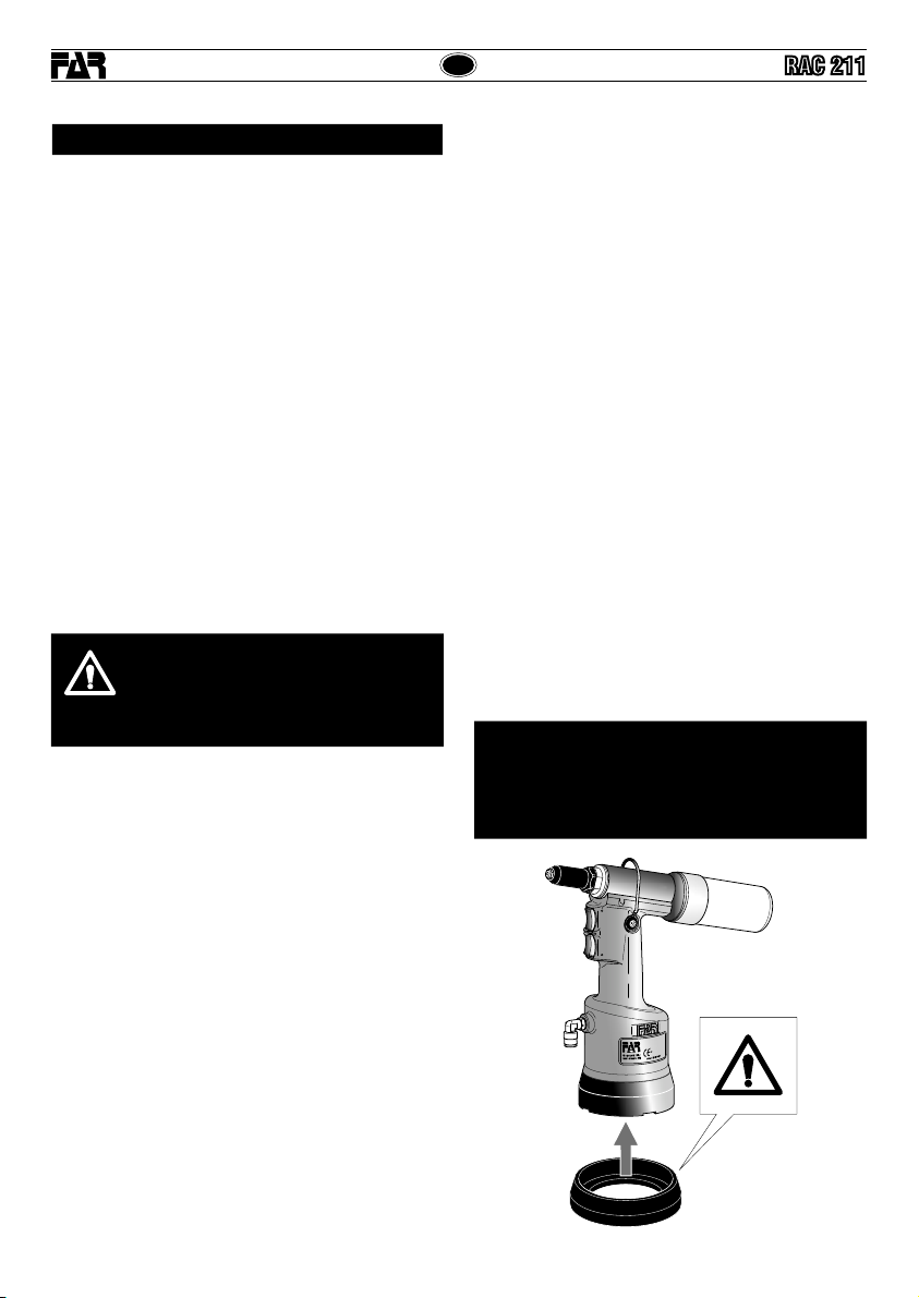
ATTENZIONE!!!
Prima di utilizzare la rivettatrice, montare il fondello di protezione
in dotazione, come evidenziato nella figura sottostante.
FARdeclinaogniresponsabilitàpereventualidanniallarivettatrice,
persone o cose causati dalla mancata presenza del fondello.
• Leggere attentamente le istruzioni prima dell’uso.
• Per le operazioni di manutenzione e/o riparazione affidarsi
a centri di assistenza autorizzati dalla FAR s.r.l. e fare uso
esclusivo di pezzi di ricambio originali. La FAR s.r.l. declina
ogni responsabilità per danni da particolari difettosi, che
si dovessero verificare per inadempienza di quanto sopra
(Direttiva CEE 85/374).
L’ELENCO DEI CENTRI DI ASSISTENZA È DISPONIBILE SUL NS.
SITO WEB: http://www.far.bo.it ( Organizzazione )
• Si raccomanda l’uso dell’utensile da parte di personale
specializzato.
• Usare durante l’impiego dell’utensile, occhiali o visiere
protettive e guanti.
• Per eseguire le operazioni di manutenzione e/o di regolazione
dell’utensile utilizzare gli accessori in dotazione e/o le
attrezzature commerciali indicate nel capitolo Manutenzione.
• Per le operazioni di carica olio usare solo fluidi con
caratteristiche indicate nel presente fascicolo.
• In caso di perdite accidentali di olio che dovessero venire a
contatto con la pelle, lavarsi accuratamente con acqua e sapone
alcalino.
• L’utensile può essere trasportato a mano ed è consigliabile
dopo l’uso riporlo nel proprio imballo.
• Non esistono particolari prescrizioni per lo stoccaggio o
l'immagazzinamento.
• Si consiglia ai fini di un corretto funzionamento della rivettatrice,
una revisione semestrale.
• Gli interventi di riparazione e pulizia dell’utensile dovranno
essere eseguiti con macchina non alimentata.
• È consigliabile, ove possibile, I’uso di un bilanciatore di
sicurezza.
• In caso di esposizione quotidiana personale in ambiente il
cui livello di pressione acustica dell'emissione ponderata A
sia superiore al limite di sicurezza di 70 dB (A), fare uso di
adeguati mezzi individuali di protezione dell’udito (cuffia o tappo
antirumore, diminuzione del tempo di esposizione quotidiana
etc..).
• Mantenere il banco e/o l’area di lavoro pulita e ordinata, il
disordine può causare danni alla persona.
• Non lasciare che persone estranee al lavoro tocchino gli utensili.
• Assicurarsi che i tubi di alimentazione dell’aria compressa siano
correttamente dimensionati per l’uso previsto.
• Non trascinare l’utensile collegato all’alimentazione tirandolo
per il tubo; mantenere quest’ultimo lontano da fonti di calore e
da oggetti taglienti.
• Mantenere gli utensili in buono stato d’uso e puliti, non
rimuovere mai le protezioni e il silenziatore dell’utensile.
• Dopo avere eseguito operazioni di riparazione e/o registrazione
assicurarsi di avere rimosso le chiavi di servizio o di
registrazione.
• Prima di scollegare il tubo dell’aria compressa dalla rivettatrice,
assicurarsi che quest’ultimo non sia in pressione.
• Attenersi scrupolosamente a queste istruzioni.
• Non utilizzare la rivettatrice in presenza di evidenti danni.
AVVERTENZE E MISURE Dl SICUREZZA

11
RAC 211
75036124 - RAC 211 – rev 00 - ( 04-2019 )
I
270
46
BA
FC
H
G
D
E
Ø 109
Ø53
I
L
260
Ø20
EAC
RAC 211
EAC
RAC 211
RAC 211
IDENTIFICAZIONE DELLA RIVETTATRICE
LarivettatriceRAC211èidentificatadaunamarcaturaindicante
ragione sociale e indirizzo, designazione della macchina ,
marcatura CE. In caso di richiesta di assistenza tecnica fare
sempre riferimento ai dati riportati nella marcatura.
DATI TECNICI
• Pressione di esercizio.................................................6 BAR
• Diametro interno minimo tubo alimentazione
aria compressa ............................................ø min. = 6 mm
• Consumo aria per ciclo...............................................3,4 Nl
• Forza massima ..............................................6 BAR-6639 N
• Peso ......................................................................1,400 Kg
• Temperatura di utilizzo..........................................-5°/+50°C
• Valore medio quadratico ponderato in
frequenza dell’accelerazione complessiva (Ac),
a cui sono sottoposte le membra superiori.........< 2,5 m/s2
• Pressione acustica dell'emmissione ponderata (A).. 70 dBA
• Pressione acustica istantanea ponderata (C) ......<130 dBC
• Potenza acustica ponderata (A) .............................. 82 dBA
PARTI PRINCIPALI
A)..................................................................................Ugello
B).............................................................Attacco bilanciatore
C)..................................................................Serbatoio chiodi
D)............................................. Pulsante apertura aspirazione
E) .............................................................Pulsante di trazione
F) ............................................................Tappo serbatoio olio
G)............................................ Allacciamento aria compressa
H)..........................................................Cannotto porta ugello
I)..........................................................Fondello di protezione
L) ..............................................................................Selettore
Ragione sociale e indirizzo
del fabbricante Designazione macchina
Numero di serie
ALIMENTAZIONE DELL’ARIA
L’aria di alimentazione deve essere libera da corpi estranei e
da umidità per proteggere la macchina da usura precoce delle
parti in movimento; è consigliabile, pertanto, l’impiego di un
gruppo lubrificatore per aria compressa.

12
RAC 211
75036124 - RAC 211 – rev 00 - ( 04-2019 )
I
EAC
RAC 211
ATTENZIONE!
Effettuarele suddette operazionicon rivettatrice
non alimentata.
USO DELLA RIVETTATRICE (fig. f1-f2)
La rivettatrice RAC 211 è dotata di un sistema di aspirazione del
chiodo,chepermettealrivettodirimanereposizionatosull’ugello
anche tenendo la testa della rivettatrice rivolta verso il basso,
aumentando notevolmente la praticità della rivettatrice; non
trattenere il rivetto con le dita! Tale dispositivo viene attivato
mediante il pulsante (D) e cessa la sua azione una volta che
questo viene rilasciato. In questo modo l’aspirazione avviene
solocontemporaneamenteallarivettatura,eliminandoiconsumi
d’aria con rivettatrice ferma. E possibile mantenere sempre
attivata l’aspirazione del chiodo tenendo premuto il pulsante
(D) e spostando lateralmente la leva (L).
Il chiodo troncato dopo il serraggio del rivetto, viene aspirato
dalla rivettatrice ed espulso dalla parte posteriore all’interno
dell’apposito serbatoio (C).
A serbatoio (C) pieno non azionare la rivettatrice, togliere
alimentazione, svitare il contenitore (C) e svuotarlo in un
apposito contenitore. NON DISPERDERE I CHIODI TRANCIATI
NELL’AMBIENTE! Riposizionare il serbatoio (C) e riprendere il
normale ciclo di lavoro.
ATTENZIONE! Non togliere per nessun motivo il
serbatoio(C)durante l’operazione dirivettatura,
poiché l’espulsione del chiodo dalla parte
posteriore della rivettatrice, può causare danni
all’operatore e a persone che si trovano in
prossimità della zona di lavoro.
f1
f2
MANUTENZIONE E CAMBIO DI FORMATO (fig. f3-f4-f5-f6)
L’utilizzoprolungatodellarivettatricepuòdarluogoalloslittamento
dei morsettl sul chiodo a causa del deposito di impurità. Si dovrà
quindiprocedereallapuliziadeisuddettimorsettiedallasuccessiva
lubrificazione oppure, in caso di usura che ne comprometta il
corretto funzionamento, alla loro sostituzione.
Smontare il cannotto porta ugello (H) servendosi di una chiave
commerciale di mm 24. Una volta rimosso il cannotto porta
ugello, servirsi di due chiavi commerciali di mm 12 e mm 14
per smontare il mandrino (M) da cui saranno estratti i morsetti
(N) . Per la sostituzione dell’ugello (A) consigliamo di servirvi
della chiave in dotazione e di montare su di essa l’ugello rimosso
dalla rivettatrice in modo da non disperderlo.
f3
f4
D
L
24 mm
H
12 mm
14 mm
M
C

13
RAC 211
75036124 - RAC 211 – rev 00 - ( 04-2019 )
I
EAC
RAC 211
f5
f6
RABBOCCO OLIO CIRCUITO OLEODINAMICO
(fig. f7)
Il rabbocco dell’olio del circuito oleodinamico si rende necessario
dopo un lungo periodo di lavoro
(15000 cicli)
, quando si avverte
un calo di corsa della rivettatrice. Procedere quindi come segue: con
rivettatriceinsostaenonalimentata,tenutainposizioneorizzontale,
rimuovere il tappo (F) servendosi della chiave a brugola di mm
5 (in dotazione), durante questa operazione prestare la massima
attenzione per evitare fuoriuscite di olio. Avvitare nella sede del
tappo (F) il contenitore a soffietto (O) preventivamente riempito
con olio idraulico commerciale con HLP 32 cSt.
Mantenendo la rivettatrice orizzontale, attivare l’alimentazione
dell’aria, premere il pulsante di trazione facendo compiere alla
rivettatrice una serie di cicli fino a quando non sia completamente
cessata l’emissione di bolle d’aria all’interno del contenitore (O),
questa condizione sta a significare che il rabbocco dell’olio è
completato. A questo punto disattivare l’alimentazione dell’aria
e, con rivettarice sempre orizzontale, svitare il contenitore olio
(O) e richiuderlo. Procedere quindi alla chiusura del tappo (F).
CAUTELA: è di estrema importanza attenersi alle istruzioni sopra
indicateedeffettuareleoperazionidirabboccooliomunitidiguanti.
Nelcasodisvuotamentocompletodelcircuitoidraulico,recuperare
tutto l’olio in un apposito contenitore e avvalersi sucessivamente
di una ditta autorizzata allo smaltimento dei rifiuti.
f7
ATTENZIONE!
Prima di scollegare il tubo dell’aria compressa
dalla rivettatrice accertarsi che quest’ultimo non
sia in pressione!
IMPORTANTE: Assicurarsi che il tappo di rabbocco
olio (F ) venga serrato con una coppia pari a:
min. 5 Nm ÷ Max. 8 Nm.
Si raccomanda l’uso di olio HLP 32 cSt o simili.
F
min. 5 Nm
Max. 8 Nm
O
SMALTIMENTO DELLA RIVETTATRICE
Per lo smaltimento della rivettatrice attenersi alle
prescrizioni imposte dalle leggi nazionali.
Dopo aver scollegato la macchina dall’impianto
pneumatico, procedere allo smontaggio dei vari
componenti suddividendoli in funzione della loro
tipologia: acciaio, alluminio, materiale plastico, ecc.
Procedere quindi alla rottamazione nel rispetto delle
leggi vigenti.
N
A

14
RAC 211
75036124 - RAC 211 – rev 00 - ( 04-2019 )
GB
EAC
RAC 211
INSTRUCTIONS FOR USE I
INDEX
GUARANTEE ............................................................................. 14
SAFETY MEASURES AND REQUIREMENTS ............................. 14
TOOL IDENTIFICATION ............................................................. 15
MAIN COMPONENTS................................................................ 15
TECHNICAL DATA ..................................................................... 15
HOW TO USE YOUR RIVETING TOOL....................................... 16
MAINTENANCE AND CHANGE OF SIZE................................ 16
TOOPING UP THE OIL-DYNAMIC CIRCUIT............................... 17
DISPOSAL OF THE RIVETING TOOL ......................................... 17
CAUTION!!!
All the operations must be done in conformity with the
safety requirements, in order to avoid any consequence
for your and other people security and to allow the best
tool work way.
• Read the instructions carefully before using the tool.
• For all maintenance and/or repairs please contact FAR
s.r.l. authorized service centers and use only original
spare parts. FAR s.r.l. may not be held liable for
damages from defective parts caused by failure to
observe what mentioned above (EEC directive
85/374).
The list of the service centres is available on our website
http://www.far.bo.it ( Organization )
• The tool must be used only by expert workers.
• A protective visor and gloves must be put on when using
the tool.
• Use equipment recommended in the maintenance chapter
to do any maintenance and/or regulation of the tool.
• For topping up the oil, we suggest using only fluids in
accordance with the features specified in this working book.
• If any drop of oil touches your skin, you must wash with
water and alkaline soap.
• The tool can be carried and we suggest putting it into its box
after using.
GUARANTEE
FAR riveting tools are covered by a 12-month warranty. The
tool warranty period starts on the date of delivery to the
buyer, as specified in the relevant document. The warranty
covers the user/buyer provided that the tool is purchased
through an authorized dealer and only if it is used for the
purposes for which it was conceived. The warranty shall
not be valid if the tool is not used or maintained as specified
in the instruction and maintenance handbook. In the event
of defects or failures, FAR S.r.l. shall undertake solely to
repair and/or replace the components it judges to be faulty.
• The tool needs a thorough six-monthly overhaul.
• There are no special requirements for storage.
• Repairing and cleaning operations must be done when the
tool is not fed.
• If it is possible, we suggest a safety balancer.
• If the A-weighted emission sound pressure level is more than
70 dB (A), you must use some hearing protections (anti-noise
headset, etc.).
• The workbench and the work surface must be always clean
and tidy. The untidy can cause damages to people.
• Do not allow unauthorized persons to use the working tools.
• Make you sure that the compressed air feeding hoses have
the correct size to be used.
• Do not carry the connected tool by pulling the hose. The hole
must be far from any heating sources or from cutting parts.
• Keep the tools in good conditions; do not remove either safety
parts or silencers.
• After repairing and/or adjusting, make sure you have already
removed the adjusting spanners.
• Before disconnecting the compressed air hose from the tool
make sure that there is no pressure in the hose.
• These instructions must be carefully followed.
• Do not use the riveting tool in the case of visible damage.
WARNING!
Before using the tool, assemble the protection bottom
supplied with the tool, as indicated in the picture below.
FAR has no responsibility for any damages on the tool,
persons or things caused by lack of the protection bottom.
SAFETY MEASURES AND REQUIREMENTS

15
RAC 211
75036124 - RAC 211 – rev 00 - ( 04-2019 )
GB
EAC
RAC 211
RAC 211
270
46
BA
FC
H
G
D
E
Ø 109
Ø53
I
L
260
Ø20
EAC
RAC 211
TOOL IDENTIFICATION
The riveting tool RAC 211 is identified from a marking that
showscompanynameandaddressofmanufacturer,designation
of the tool, CE. Always refer to the information on the riveting
tool when requesting technical service.
TECHNICAL DATA
• Working preessure .....................................................6 BAR
• Min. int. diam. of the compressed air
feeding hose ........................................ min. diam = 6 mm
• Air consumption per cycle..........................................3,4 Nl
• Maximum force..............................................6 BAR-6639 N
• Weight ...................................................................1,400 Kg
• TWorking temperature..........................................-5°/+50°C
• Root mean square in total acceleration frequency (Ac)
to which the arms are subjected. .........................< 2,5 m/s2
• A-weighted emission sound pressure level ............70 dBA
• Peak C-weighted instantaneous sound pressure .<130 dBC
• A-weighted sound power .........................................82 dBA
MAIN COMPONENTS
A)................................................................................. Nozzle
B)............................................................Balancer connection
C).................................................................... Nails container
D).......................................................Suction opening button
E) ....................................................... Tensile strenght button
F) ........................................................................Oil tank plug
G)................................................ Compressed air connection
H).............................................................Head carring nozzle
I)................................................................Protection bottom
L) ...............................................................................Selector
Company name and address Designation of the tool
Serial number
AIR FEED
The air feed must be free from foreign bodies and humidity
in order to protect the tool from premature wear and tear of
the components in movement, therefore we suggest to use a
lubrificator group for compressed air.

16
RAC 211
75036124 - RAC 211 – rev 00 - ( 04-2019 )
GB
EAC
RAC 211
WARNING!
Desconnect air feed when performing those
operations.
HOW TO USE YOUR RIVETING TOOL (fig. f1-f2)
TherivetingtoolRAC211isequippedwithasuctionnailsystem
which increases a lot the usefulness of this tool. In fact, it
allows the rivet to remain in the nozzle even turning the head
of the riveting tool downwards. Do NOT keep the rivet with
your fingers! To make the system operate, press the button
(D) and release it to exclude it. In that way, suction takes place
simultaneously with riveting, thus avoiding air consumption
when your riveting tool is idle.
It is possible to keep the suction of the nail always activated
by keeping the button (D) pressed and moving the lever (L)
sideways.
After the clamping, the sheared nail is piped by the riveting
tool and ejected from the back into the proper container (C).
When the container (C) is full of nails do not use the riveting
tool. Disconnect the tool, unscrew the container (C) and empty
it. DO NOT DISPERSE ANY NAIL! Screw the container and
start again to work.
WARNING! Do not remove the container (C)
duringtheriveting operation, as thenail ejection
can cause damages to the worker or to persons
who are nearby the work surface.
MAINTENACE AND CHANGE OF SIZE (fig. f3-f4-f5-f6)
Theextendedutilizationoftherivetingtoolcancausetheslipping
of the clamps on the nail due to the deposited impurities. For this
reason,itisnecessarytolubricatetheclampsafterhavingcleaned
them with benzine or derivates. However, if clamps are worn out
andasaconsequencetheirworkingisjeopardized,replacethem.
First remove the head which carries the nozzle (H) , by means
of a standard spanner of 24 mm. Then, by using two standard
spanners of 12 mm and 14 mm, remove the chuck (M) and
extract the clamps (N) .
When replacing the nozzle (A) , we recommend to use the
supplied wrench and fit the removed nozzle in it in order to
avoid losing the nozzle.
f3
f4
24 mm
H
12 mm
14 mm
M
f1
f2
D
L
C

17
RAC 211
75036124 - RAC 211 – rev 00 - ( 04-2019 )
GB
EAC
RAC 211
f5
f6
TOPPING UP THE OIL-DYNAMIC CIRCUIT (fig. f7)
You need to top up the oil-dynamic circuit after a long period of
work
(15000 cycles)
,whenyounoteapowerloss.Puttheriveting
tool (
DWELL AND NOT FED
) in a horizontal position and remove
the plug (
F
) , by means of a 5 mm Allen wrench (equipped with the
riveting tool); during this operation, check the oil level in order to
avoid any overflowing. Then, slowly pour the oil
HLP 32 cSt
into
the bellows container (
O
) which shall be screwed to its seat on the
plug (
F
) . While keeping the riveting tool in a horizontal position
and starting air feeding, push the tensile strength button and make
the riveting tool carry out some cycles until air bubbles inside the
container (
O
) stop coming out. This condition indicates that the
topping up of the oil has fully been achieved. At this point
stop
the air feeding
and, while keeping the riveting tool in a horizontal
position,unscrewandcloseupthecontainer (
O
) andtheplug(
F
).
WARNING:
it is very important to follow the about mentioned
instructionsandusegloves.Ifyouneedtoemptyfullythehydraulic
circuit, you must put the oil in a suitable container and contact a
Company that is authorized to discharge any waste.
ATTENTION!
Before disconnecting the compressed air hose,
make sure that it is not under pressure!
ATTENTION: Make sure that the oil filler cap (F )
is tightened at a torque corresponding to min. 5
Nm ÷ Max. 8 Nm.
We recommend to use oil HLP 32 cSt or similars.
DISPOSAL OF THE RIVETING TOOL
Follow the prescriptions of the national laws for
disposing of the riveting tool.
After disconnecting the tool from the pneumatic
system, disassemble and split all the components
according to the material: steel, aluminium, plastic
material, etc.
Then proceed to scrap the materials in accordance
with current laws.
N
A
f7
F
O
min. 5 Nm
Max. 8 Nm

18
RAC 211
75036124 - RAC 211 – rev 00 - ( 04-2019 )
F
EAC
RAC 211
MODE D’EMPLOI
INDEX
GARANTIE................................................................................. 18
INSTRUCTIONS ET MESURES DE SECURITE........................... 18
IDENTIFICATION DE L’OUTIL DE POSE..................................... 19
PARTIES PRINCIPALES ............................................................ 19
DONNES TECHNIQUES ............................................................. 19
MODE D’EMPLOI ...................................................................... 20
ENTRETIEN ET CHANGEMENT DE FORMAT.............................. 20
REMPLISSAGE DE L’HUILE DU CIRCUIT HYDRAULIQUE......... 21
ELIMINATION DE LA RIVETEUSE.............................................. 21
ATTENTION!!!
Le non respect des instructions suivantes peut
avoir des conséquences désagréables pour
vous-mêmes et pour l’intégrité d’autrui.
• Lisez avec soin la notice avant l’usage.
• Pour les opérations d’entretien et/ou réparations, adressez-vous
aux centres de service après-vente autorisés de FAR s.r.l. et
n’utilisez que des pièces détachées originales. FAR s.r.l.
décline toute responsabilité pour les dommages dus à des
pièces défectueuses qui interviendraient suite au non-respect
de la notice ci-dessus (Directive CEE 85/374).
La liste des centres d’assistance est disponible sur notre site
internet http://www.far.bo.it ( Organisation )
• L’outil de pose doit être utilisé par le personnel spécialisé.
• Pendant l’utilisation de l’outil utiliser des gants et des lunettes
de protections ou une visière
• Pour l’entretien et/ou réglage de l’outil de pose, se servir
des équipements indiqués dans le chapitre “ENTRETIEN”.
• Pour le remplissage de l’huile, il faut utiliser les fluides indiqués
dans ce dossier.
• En cas de fuites imprévues de huile (au contact de la peau), il
faut se laver soigneusement avec de l’eau et du savon alcalin.
• L’outil de pose peut être transporté à la main et il doit être remis
dans sa boîte après l’usage.
•Il n’y a pas de prescriptions particulières pour le stockage.
• Pour obtenir un bon fonctionnement de l’outil, nous vous
suggérons de le réviser tous les six mois.
• Il faut faire la réparation et le nettoyage de l’outil quand il
n’est pas alimenté.
• Si possible, il faudrait utiliser des équilibreurs de sécurité.
• En cas d’exposition quotidienne où le niveau de pression soit
supérieur à la limite de sécurité 70 dB (A), l’on doit s’assurer
la protection de l’ouïe (casque antibruit, réduction du temps
d’exposition quotidienne, etc).
• La table et la place de travail doivent être toujours propres
et rangées. Le désordre peut causer des dommages aux
personnes.
• Personne (si étranger) ne peut utiliser les outils de pose.
• Il faut s’assurer que les tuyaux d’alimentation de l’air
comprimé soient appropriés (conformes) à l’utilisation
prévue.
• Ne pas traîner l’outil de pose quand il est connecté à
l’alimentation. Le tuyau doit se trouver toujours loin de
sources de chaleur ou d’objets tranchants.
• Les outils de pose doivent être toujours en bon état. Ne pas
enlever les protections et le silencieux de l’outil.
• Après la réparation et/ou réglage, il faut s’assurer d’avoir
enlever les clés de réglage.
• Avant de déconnecter le tuyau de l’air comprimé de l’outil de
pose, il faut s’assurer qu’il ne soit pas en pression.
• Suivre scrupuleusement ces instructions.
• L’outil à riveter ne doit pas être utilisé en présence de
dommages évidents.
GARANTIE
Les riveteuses FAR sont sous garantie pendant 12 mois. La
période de garantie de l'outil commence à partir du moment
où il est avéré que son acquéreur en prend possession. La
garantiecouvrel'utilisateur/acquéreurquandl'outilestacheté
chez un revendeur agréé et uniquement quand il est utilisé
aux fins pour lesquelles il a été conçu. La garantie n'est pas
valable si l'outil n'est pas utilisé et s'il n'est pas soumis à
l'entretien tel qu'il est spécifié dans le manuel d'utilisation et
d'entretien. En cas de défauts ou de pannes, la société FAR
S.r.l. s'engage uniquement à réparer et/ou à remplacer, à sa
seule discrétion, les composants jugés défectueux.
ATTENTION!
Avant d’utiliser l’outil, veuillez l’équiper du culot de
protection (suivant la figure ci-dessous).
La société FAR n’est pas responsable des éventuels
dommages occasionnés à l’outil, personnes ou choses
par manque du culot.
INSTRUCTIONS ET MESURES DE SECURITE

19
RAC 211
75036124 - RAC 211 – rev 00 - ( 04-2019 )
F
EAC
RAC 211
RAC 211
270
46
BA
FC
H
G
D
E
Ø 109
Ø53
I
L
260
Ø20
EAC
RAC 211
IDENTIFICATION DE L’OUTIL DE POSE
L’outilde pose RAC211est identifiéparun marquage indiquant
raison sociale et adresse du fabricant, désignation de l’outil de
pose, marquage
CE.
En cas de recours au service après-vente, il faut toujours se
référer aux données indiquées sur la riveteuse.
DONNES TECHNIQUES
• Pression d’utilization ..................................................6 BAR
• Diamètre int. min. tuyau alimentation
air comprimé .......................................... min. diam = 6 mm
• Consommation d’air par cycle ....................................3,4 Nl
• Force maximum.............................................6 BAR-6639 N
• Poids .....................................................................1,400 Kg
• Température d’utilisation ......................................-5°/+50°C
• Valeur moyenne quadratique pondérée en fréquence de
l’accélération totale (Ac)
à laquelle les bras sont soumis........................... < 2,5 m/s2
• Pression acoustique de l’émission pondéré (A) .....70 dBA
• Pression acoustique instantanée pondéré (C) ..... <130 dBC
• Puissance acoustique pondérée (A) ........................ 82 dBA
PARTIES PRINCIPALES
A)....................................................................................Buse
B)................................................................. Etrier de support
C)................................................... Bol de récupération clous
D)................................................Bouton ouverture aspiration
E) .............................................................. Bouton de traction
F) .............................................Orifice de remplissage d’huile
G)......................................................Raccord d’air comprimè
H)................................................................... Tête porte buse
I)...............................................................Culot de protection
L) .............................................................................Sélecteur
Raison sociale et adresse Designation de l’outil de pose
Numéro de série
ALIMENTATION EN AIR
L’air d’alimentation doit être libre de corps étrangers et
d’humidité pour sauvegarder l’outil de l’usure précoce des
parties en mouvement, donc il est recommandé d’employer
un groupe de graissage pour air comprimè.

20
RAC 211
75036124 - RAC 211 – rev 00 - ( 04-2019 )
F
EAC
RAC 211
ATTENTION!
Effectuer les operations susmentionnees le
pistolet n’etant pas alimente!
MODE D’EMPLOI (fig. f1-f2)
L’outilàriveterRAC211estéquipéd’unsystèmed’aspirationdu
clou qui lui permet de rester dans la buse, tout en maintenant
la tête de l’outil vers le bas, ce qui favorise considérablement,
l’emploi de l’outil. Ne pas retenir le rivet avec les doigts!
Ce dispositif est actionné par le bouton (D) et cesse son action
lorsqueleboutonestrelâché.Decette façon l’aspiration n’a lieu
que pendant le rivetage, supprimant ainsi les consommations
d’air lorsque le pistolet à riveter n’est pas utilisé.
Il est possible de maintenir l'aspiration du clou toujours
activée en appuyant sur le bouton (D) et en déplaçant le levier
latéralement (L).
Aprèsleserragedurivet,lecloucoupéestentraînéparlepistolet
et expulsé dans le récupérateur en plastique pour les clous (C).
Ne pas actionner l’outil de pose quand le conteneur (C) est
plein; déconnecter l’outil, dévisser le conteneur (C) et le vider
dans un conteneur spécial. NE PAS DISPERSER LES CLOUS!
Visser le conteneur (C) et commencer de nouveau à travailler.
ATTENTION!
Ne pas enlever pour aucune raison le conteneur
(C) pendant le rivetage, car l’éjection du clou
peut causer des dommages à l’opérateur et
aux personnes qui se trouvent à proximité du
secteur de travail.
ENTRETIEN ET CHANGEMENT DE FORMAT
L’utilisationprolongéedu pistoletpeutprovoquer le glissement
desmorssur le clou,à causede dépôtd’impurité.Ilfaudra donc
nettoyer les mors à l’aide de benzine ou dérivés et, en suite,
les lubrifier. En cas d’usure, si elle comporte une altération de
leur correct fonctionnement, il faudra au contraire remplacer
les mors mêmes.
Enlever la tête porte buse (H) en utilisant une clé commerciale
de 24 mm. ensuite, au moyen de deux clés commerciales de
12 mm et 14 mm enlever la broche (M) , d’où on doit extraire
les mors (N) . Pour le remplacement de la buse (A) , il est
conseillé d’utiliser la clé fournie, sur laquelle on doit monter la
buse enlevée du pistolet pour éviter de perdre la buse même.
f3
f4
24 mm
H
12 mm
14 mm
M
f1
f2
D
L
C
Table of contents
Languages:
Other FAR Power Tools manuals
Popular Power Tools manuals by other brands

fann
fann 300 Series instruction manual

Bosch
Bosch GSH 27 VC Professional Original instructions

Briggs & Stratton
Briggs & Stratton 71 Piece Air Tool Kit Operator's manual

Norton
Norton clipper CT 601 B operating instructions

Parkside
Parkside PDSP 1000 B2 Operation manuals

Hakko Electronics
Hakko Electronics FM-2023 instruction manual

SW-Stahl
SW-Stahl 03719L instruction manual

Flex
Flex F 1509 FR operating instructions

Sealey
Sealey GSA12 instructions

Palmgren
Palmgren 0.5-Ton Arbor Press Operating manual & parts list

Bosch
Bosch GDS Professional 18V-1000 Original instructions

N.KO
N.KO UZ 12 Ultralight Instructions for use and maintenance