Application Note AN201202
phase-technology.com 11168 Hammersmith Gate, Richmond BC Canada V7A 5H8 Tel (604)241-9568 Fax (604) 241-9569
Procedure
Remove the analyzer cover
1. Ground yourself by touching the metal surface of the analyzer.
2. Shut down the analyzer and remove the power cord from rear of the analyzer.
3. Remove all Phillips screws from the left and right sides of the cover.
4. Open the chamber lid by about 45o. Gently lift the rear of the cover upwards,rotating on the
cover’s front edge, until the square opening on the top of the cover clears the chamber lid.
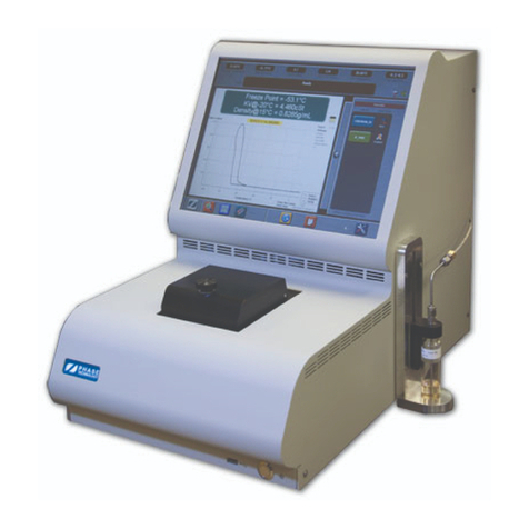
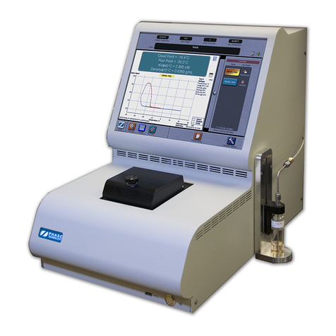
5. Slowly lift the cover off of the instrument and place in a safe location (Figure 1).
Figure 2. Remove the analyzer cover
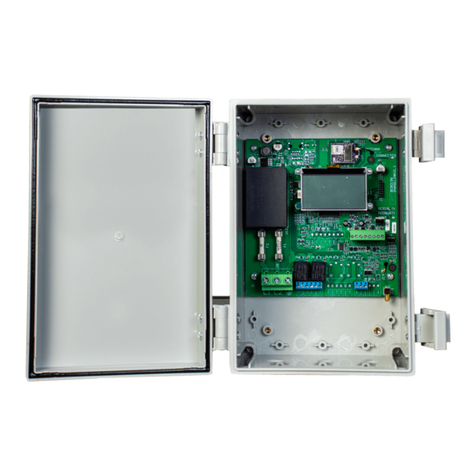
Remove and replace the solenoid board (Refer to Figure 1)
1. Use a small slotted screwdriver to unfasten the screws that lock the connectors T1, P1, P2 and
P4 onto the Solenoid Board. NOTE: Some manual dexterity is required to perform this task, as
well as the following steps. Please proceed carefully, and do not to bend any of the purge
tubing that runs near the Solenoid Board.
2. Remove the four connectors by pulling on the body of the connector, not the wires. If any of the
connectors resist, it may be because the screw is not entirely unscrewed from the housing.
3. Release the four 1x4 connectors on the bottom of the board by pushing the latch on the bottom-
side of the connectors. The amount of room between the purge pump and the connectors on the board
is limited. A useful technique is to push the latch with one hand and pull on the connector with the
other. NOTE: Be careful not to bend or kink any of the tubing while doing so.
4. Use a small slotted screwdriver to remove the four screws (one on each corner) and
washers. Hold the board lightly as you remove the last screw so that the board does not fall.
NOTE: Be very careful not to lose or drop any of the washers inside the analyzer.
5. Place the old Solenoid Board into an anti-static bag.
6. Install the new Solenoid Board using the four screws and washers removed in step 4.
Install each screw and washer only about half-way until all four are on, to make sure that the
board is properly aligned; then tighten all of the screws.
7. Insert the DataLink Cable into the housing at J3 on the Solenoid Board.
8. Insert the Fan connector into the housing at J5 on the Solenoid Board.
9. Insert the CANBUS Cable into the housing at J1 on the Solenoid Board.
10. Insert the PPC Connector into the housing at LJ1 on the Solenoid Board.


