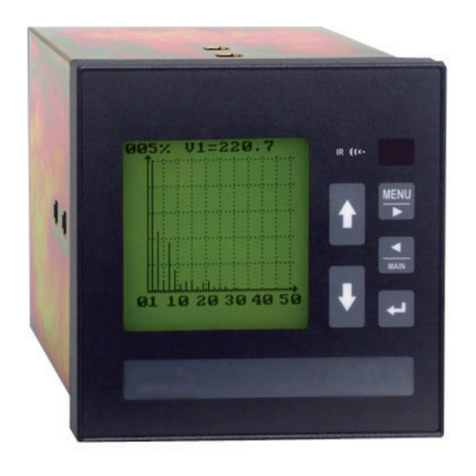
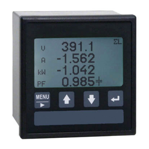
Algodue ELETTRONICA UPM307 User manual

MODBUS protocol manual
English
Rev. 008 - 10/07/2012
1MAUMD307008
UPM307
DIN 96x96 Compact Power Meter
Universal Power Meter

A
ENGLISH
Table of contents
MODBUS protocol manual
Table of conTenTs
1. InTRoDUcTIon ...............................................................1-1
2. sYMbols ........................................................................2-1
3. DescRIPTIon ..................................................................3-1
3.1 LRC generation ...........................................................................3-3
3.2 CRC generation ...........................................................................3-4
4. ReaD ReGIsTeRs ............................................................4-1
4.1 Floating point as per IEEE Standard ...........................................4-3
5. PaRaMeTeRs seTUP ......................................................5-1
6. eXcePTIon coDes .........................................................6-1
7. ReGIsTeRs Table...........................................................7-1
7.1 Important notes for registers ......................................................7-1
7.2 Measured values.......................................................................... 7-2
7.3 Harmonics values ........................................................................7-6
7.4 Read only parameters .................................................................7-8
7.5 Read & Write parameters............................................................7-8
7.6 Variables list ...............................................................................7-11

1-1
ENGLISH
Introduction
MODBUS protocol manual
1. INTRODUCTION
This manual provides information on the MODBUS communication protocol. The publication is not
intended for general use, but for qualified technicians.
This term indicates a professional and skilled technician, authorised to act in accordance with the
safety standards relating to the dangers posed by electric current.
This person must also have basic first-aid training and be in possession of suitable Personal
Protective Equipment.
WARNING!
It is strictly forbidden, for anyone who does not have the above-mentioned features, to
install or use the device.
The device is made in compliance with the European Union directives in force, as well as in compliance
with the technical standards implementing these requirements, as certified by the CE mark on the
device and in this manual.
It is strictly forbidden to use the instrument for purposes other than those intended, which can be
deduced from the manual content.
The Manufacturer reserves the right to make changes on the device or in the device specifications
identified in this manual without notice.
The Manufacturer declines all liability for any use of the instrument which is different from that
described in this manual and in the instrument manual, or for the lack/incorrect application of the
reported instructions.
The information, contained in this manual, may not be divulged to third parties. Any copy of this
manual, either partial or total, by photocopying, or by other means, also electronically, without written
authorization from the Manufacturer, violates the copyright and is punishable by law.
The information contained in this document is believed to be accurate at the time of publication,
however, the Manufacturer assumes no responsability for any errors which may appear here and
reserves the right to make changes without notice.
Any brands mentioned in the publication are property of their respective owners.

2-1
ENGLISH
Symbols
MODBUS protocol manual
2. SYMBOLS
In the manual and on the device, some instructions are highlighted by symbols to draw the reader’s
attention to the operational dangers.
These symbols are the following:
DANGER!
This warning indicates the possible presence of voltage exceeding 1kV on the marked
terminals (even for short periods).
WARNING!
This warning indicates the possible occurrence of an event which may cause a serious
accident or considerable damage to the device if suitable precautionary countermeasures
are not taken.
ATTENTION!
This warning indicates the possible occurrence of an event which may cause a light accident
or damage to the device if suitable precautionary countermeasures are not taken.
NOTE
This warning indicates important information which must be read carefully.

3-1
ENGLISH
Description
MODBUS protocol manual
3. DESCRIPTION
MODBUS ASCII/RTU is a master-slave communication protocol, able to support up to 247 slaves
connected in a bus or a star network.
The protocol uses a simplex connection on a single line. In this way, the communication messages
move on a single line in two opposite directions.
MODBUS TCP is a variant of the MODBUS family. Specifically, it covers the use of MODBUS messaging
in an “Intranet” or “Internet” environment using the TCP/IP protocol on a fixed port 502.
Master-slave messages can be:
Reading ($03)• : the communication is between the master and a single slave. It allows to read
information about the queried instrument
Writing ($10)• : the communication is between the master and a single slave. It allows to
change the instrument settings
Broadcast(notavailableforMODBUSTCP)• : the communication is between the master and all
the connected slaves. It is always a write command ($10) and required logical number $00
In a multi-point type connection (MODBUS ASCII/RTU), slave address (called also logical number)
allows to identify each instrument during the communication. Each instrument is preset with a
default slave address (01) and the user can change it.
In case of MODBUS TCP, slave address is replaced by a single byte, the Unit identifier.

3-2
ENGLISH
Description
MODBUS protocol manual
COMMUNICATION FRAME STRUCTURE
ASCII mode
Bit per byte: 1 Start, 7 Bit, Even, 1 Stop (7E1)
Name Length Function
START FRAME 1 char Message start marker. Starts with colon “:” ($3A)
ADDRESS FIELD 2 chars Instrument logical number
FUNCTION CODE 2 chars Function code ($03=read command, $10=write command)
DATA FIELD n chars Data + length will be filled depending on the message type
ERROR CHECK 2 chars Error check (LRC)
END FRAME 2 chars Carriage return - line feed (CRLF) pair ($0D & $0A)
RTU mode
Bit per byte: 1 Start, 8 Bit, None, 1 Stop (8N1)
Name Length Function
START FRAME 4 chars idle At least 4 character time of silence (MARK condition)
ADDRESS FIELD 8 bits Instrument logical number
FUNCTION CODE 8 bits Function code ($03=read command, $10=write command)
DATA FIELD n x 8 bits Data + length will be filled depending on the message type
ERROR CHECK 16 bits Error check (CRC)
END FRAME 4 chars idle At least 4 character time of silence between frames
TCP mode
Bit per byte: 1 Start, 7 Bit, Even, 2 Stop (7E2)
Name Length Function
TRANSACTION ID 2 bytes For synchronization between messages of server & client
PROTOCOL ID 2 bytes Zero for MODBUS TCP
BYTE COUNT 2 bytes Number of remaining bytes in this frame
UNIT ID 1 byte Slave address (255 if not used)
FUNCTION CODE 1 byte Function code ($03=read command, $10=write command)
DATA BYTES n bytes Data as response or command

3-3
ENGLISH
Description
MODBUS protocol manual
3.1 LRC generation
The Longitudinal Redundancy Check (LRC) field is one byte, containing an 8–bit binary value.
The LRC value is calculated by the transmitting device, which appends the LRC to the message.
The receiving device recalculates an LRC during receipt of the message, and compares the
calculated value to the actual value it received in the LRC field. If the two values are not
equal, an error results. The LRC is calculated by adding together successive 8–bit bytes in
the message, discarding any carries, and then two’s complementing the result. The LRC is an
8–bit field, therefore each new addition of a character that would result in a value higher than
255 decimal simply ‘rolls over’ the field’s value through zero. Because there is no ninth bit, the
carry is discarded automatically.
A procedure for generating an LRC is:
1. Add all bytes in the message, excluding the starting ‘colon’ and ending CR LF. Add them
into an 8–bit field, so that carries will be discarded.
2. Subtract the final field value from $FF, to produce the ones–complement.
3. Add 1 to produce the twos–complement.
PLACING THE LRC INTO THE MESSAGE
When the the 8–bit LRC (2 ASCII characters) is transmitted in the message, the high–order
character will be transmitted first, followed by the low–order character. For example, if the
LRC value is $52 (0101 0010):
Colon
‘:’
Addr Func Data
Count
Data Data …. Data LRC
Hi ‘5’
LRC
Lo‘2’
CR LF
C-function calculate LRC
*pucFrame – pointer on “Addr” of message
usLen – length message from “Addr” to end “Data”
UCHAR prvucMBLRC( UCHAR * pucFrame, USHORT usLen )
{
UCHAR ucLRC = 0; /* LRC char initialized */
while( usLen-- )
{
ucLRC += *pucFrame++; /* Add buffer byte without carry */
}
/* Return twos complement */
ucLRC = ( UCHAR ) ( -( ( CHAR ) ucLRC ) );
return ucLRC;
}

3-4
ENGLISH
Description
MODBUS protocol manual
3.2 CRC generation
The Cyclical Redundancy Check (CRC) field is two bytes, containing a 16–bit value. The CRC value is
calculated by the transmitting device, which appends the CRC to the message. The receiving device
recalculates a CRC during receipt of the message, and compares the calculated value to the actual
value it received in the CRC field. If the two values are not equal, an error results.
The CRC is started by first preloading a 16–bit register to all 1’s. Then a process begins of applying
successive 8–bit bytes of the message to the current contents of the register. Only the eight bits of
data in each character are used for generating the CRC. Start and stop bits, and the parity bit, do
not apply to the CRC.
During generation of the CRC, each 8–bit character is exclusive ORed with the register contents. Then
the result is shifted in the direction of the least significant bit (LSB), with a zero filled into the most
significant bit (MSB) position. The LSB is extracted and examined. If the LSB was a 1, the register is
then exclusive ORed with a preset, fixed value. If the LSB was a 0, no exclusive OR takes place.
This process is repeated until eight shifts have been performed. After the last (eighth) shift, the
next 8–bit character is exclusive ORed with the register’s current value, and the process repeats for
eight more shifts as described above. The final contents of the register, after all the characters of
the message have been applied, is the CRC value.
A calculated procedure for generating a CRC is:
1. Load a 16–bit register with $FFFF. Call this the CRC register.
2. Exclusive OR the first 8–bit byte of the message with the low–order byte of the 16–bit CRC regi-
ster, putting the result in the CRC register.
3. Shift the CRC register one bit to the right (toward the LSB), zero–filling the MSB. Extract and
examine the LSB.
4. (If the LSB was 0): Repeat Step 3 (another shift).
(If the LSB was 1): Exclusive OR the CRC register with the polynomial value $A001 (1010 0000
0000 0001).
5. Repeat Steps 3 and 4 until 8 shifts have been performed. When this is done, a complete 8–bit
byte will have been processed.
6. Repeat Steps 2 through 5 for the next 8–bit byte of the message. Continue doing this until all
bytes have been processed.
7. The final contents of the CRC register is the CRC value.
8. When the CRC is placed into the message, its upper and lower bytes must be swapped as de-
scribed below.
PLACING THE CRC INTO THE MESSAGE
When the 16–bit CRC (two 8–bit bytes) is transmitted in the message, the low-order byte will be
transmitted first, followed by the high-order byte.
For example, if the CRC value is $35F7 (0011 0101 1111 0111):
Addr Func Data
Count
Data Data …. Data CRC
lo F7
CRC
hi 35

3-5
ENGLISH
Description
MODBUS protocol manual
TABLE CRC GENERATION FUNCTIONS
All of the possible CRC values are preloaded into two arrays, which are simply indexed as the function
increments through the message buffer. One array contains all of the 256 possible CRC values for
the high byte of the 16–bit CRC field, and the other array contains all of the values for the low byte.
Indexing the CRC in this way provides faster execution than would be achieved by calculating a new
CRC value with each new character from the message buffer.
/*CRC table for calculate with polynom 0xA001 with init value 0xFFFF, High half word*/
rom unsigned char CRC_Table_Hi[] = {
0x00, 0xC1, 0x81, 0x40, 0x01, 0xC0, 0x80, 0x41, 0x01, 0xC0, 0x80, 0x41, 0x00, 0xC1, 0x81,
0x40, 0x01, 0xC0, 0x80, 0x41, 0x00, 0xC1, 0x81, 0x40, 0x00, 0xC1, 0x81, 0x40, 0x01, 0xC0,
0x80, 0x41, 0x01, 0xC0, 0x80, 0x41, 0x00, 0xC1, 0x81, 0x40, 0x00, 0xC1, 0x81, 0x40, 0x01,
0xC0, 0x80, 0x41, 0x00, 0xC1, 0x81, 0x40, 0x01, 0xC0, 0x80, 0x41, 0x01, 0xC0, 0x80, 0x41,
0x00, 0xC1, 0x81, 0x40, 0x01, 0xC0, 0x80, 0x41, 0x00, 0xC1, 0x81, 0x40, 0x00, 0xC1, 0x81,
0x40, 0x01, 0xC0, 0x80, 0x41, 0x00, 0xC1, 0x81, 0x40, 0x01, 0xC0, 0x80, 0x41, 0x01, 0xC0,
0x80, 0x41, 0x00, 0xC1, 0x81, 0x40, 0x00, 0xC1, 0x81, 0x40, 0x01, 0xC0, 0x80, 0x41, 0x01,
0xC0, 0x80, 0x41, 0x00, 0xC1, 0x81, 0x40, 0x01, 0xC0, 0x80, 0x41, 0x00, 0xC1, 0x81, 0x40,
0x00, 0xC1, 0x81, 0x40, 0x01, 0xC0, 0x80, 0x41, 0x01, 0xC0, 0x80, 0x41, 0x00, 0xC1, 0x81,
0x40, 0x00, 0xC1, 0x81, 0x40, 0x01, 0xC0, 0x80, 0x41, 0x00, 0xC1, 0x81, 0x40, 0x01, 0xC0,
0x80, 0x41, 0x01, 0xC0, 0x80, 0x41, 0x00, 0xC1, 0x81, 0x40, 0x00, 0xC1, 0x81, 0x40, 0x01,
0xC0, 0x80, 0x41, 0x01, 0xC0, 0x80, 0x41, 0x00, 0xC1, 0x81, 0x40, 0x01, 0xC0, 0x80, 0x41,
0x00, 0xC1, 0x81, 0x40, 0x00, 0xC1, 0x81, 0x40, 0x01, 0xC0, 0x80, 0x41, 0x00, 0xC1, 0x81,
0x40, 0x01, 0xC0, 0x80, 0x41, 0x01, 0xC0, 0x80, 0x41, 0x00, 0xC1, 0x81, 0x40, 0x01, 0xC0,
0x80, 0x41, 0x00, 0xC1, 0x81, 0x40, 0x00, 0xC1, 0x81, 0x40, 0x01, 0xC0, 0x80, 0x41, 0x01,
0xC0, 0x80, 0x41, 0x00, 0xC1, 0x81, 0x40, 0x00, 0xC1, 0x81, 0x40, 0x01, 0xC0, 0x80, 0x41,
0x00, 0xC1, 0x81, 0x40, 0x01, 0xC0, 0x80, 0x41, 0x01, 0xC0, 0x80, 0x41, 0x00, 0xC1, 0x81,
0x40
};
/*CRC table for calculate with polynom 0xA001 with init value 0xFFFF, Low half word*/
rom unsigned char CRC_Table_Lo[] = {
0x00, 0xC0, 0xC1, 0x01, 0xC3, 0x03, 0x02, 0xC2, 0xC6, 0x06, 0x07, 0xC7, 0x05, 0xC5, 0xC4,
0x04, 0xCC, 0x0C, 0x0D, 0xCD, 0x0F, 0xCF, 0xCE, 0x0E, 0x0A, 0xCA, 0xCB, 0x0B, 0xC9, 0x09,
0x08, 0xC8, 0xD8, 0x18, 0x19, 0xD9, 0x1B, 0xDB, 0xDA, 0x1A, 0x1E, 0xDE, 0xDF, 0x1F, 0xDD,
0x1D, 0x1C, 0xDC, 0x14, 0xD4, 0xD5, 0x15, 0xD7, 0x17, 0x16, 0xD6, 0xD2, 0x12, 0x13, 0xD3,
0x11, 0xD1, 0xD0, 0x10, 0xF0, 0x30, 0x31, 0xF1, 0x33, 0xF3, 0xF2, 0x32, 0x36, 0xF6, 0xF7,
0x37, 0xF5, 0x35, 0x34, 0xF4, 0x3C, 0xFC, 0xFD, 0x3D, 0xFF, 0x3F, 0x3E, 0xFE, 0xFA, 0x3A,
0x3B, 0xFB, 0x39, 0xF9, 0xF8, 0x38, 0x28, 0xE8, 0xE9, 0x29, 0xEB, 0x2B, 0x2A, 0xEA, 0xEE,
0x2E, 0x2F, 0xEF, 0x2D, 0xED, 0xEC, 0x2C, 0xE4, 0x24, 0x25, 0xE5, 0x27, 0xE7, 0xE6, 0x26,
0x22, 0xE2, 0xE3, 0x23, 0xE1, 0x21, 0x20, 0xE0, 0xA0, 0x60, 0x61, 0xA1, 0x63, 0xA3, 0xA2,
0x62, 0x66, 0xA6, 0xA7, 0x67, 0xA5, 0x65, 0x64, 0xA4, 0x6C, 0xAC, 0xAD, 0x6D, 0xAF, 0x6F,
0x6E, 0xAE, 0xAA, 0x6A, 0x6B, 0xAB, 0x69, 0xA9, 0xA8, 0x68, 0x78, 0xB8, 0xB9, 0x79, 0xBB,
0x7B, 0x7A, 0xBA, 0xBE, 0x7E, 0x7F, 0xBF, 0x7D, 0xBD, 0xBC, 0x7C, 0xB4, 0x74, 0x75, 0xB5,
0x77, 0xB7, 0xB6, 0x76, 0x72, 0xB2, 0xB3, 0x73, 0xB1, 0x71, 0x70, 0xB0, 0x50, 0x90, 0x91,
0x51, 0x93, 0x53, 0x52, 0x92, 0x96, 0x56, 0x57, 0x97, 0x55, 0x95, 0x94, 0x54, 0x9C, 0x5C,
0x5D, 0x9D, 0x5F, 0x9F, 0x9E, 0x5E, 0x5A, 0x9A, 0x9B, 0x5B, 0x99, 0x59, 0x58, 0x98, 0x88,
0x48, 0x49, 0x89, 0x4B, 0x8B, 0x8A, 0x4A, 0x4E, 0x8E, 0x8F, 0x4F, 0x8D, 0x4D, 0x4C, 0x8C,
0x44, 0x84, 0x85, 0x45, 0x87, 0x47, 0x46, 0x86, 0x82, 0x42, 0x43, 0x83, 0x41, 0x81, 0x80,
0x40
};

3-6
ENGLISH
Description
MODBUS protocol manual
unsigned short ModBus_CRC16( unsigned char * Buffer, unsigned short Length )
{
unsigned char CRCHi = 0xFF;
unsigned char CRCLo = 0xFF;
int Index;
unsigned short ret;
while( Length-- )
{
Index = CRCLo ^ *Buffer++ ;
CRCLo = CRCHi ^ CRC_Table_Hi[Index];
CRCHi = CRC_Table_Lo[Index];
}
ret=((unsigned short)CRCHi << 8);
ret|= (unsigned short)CRCLo;
return ret;
}
OR CAN BE USED CALCULATED METHOD WITHOUT TABLE
/* ModBus_CRC16 Calculatd CRC16 with polynome 0xA001 and init value 0xFFFF
Input *Buffer - pointer on data
Input Lenght - number byte in buffer
Output - calculated CRC16
*/
/*
cur_crc=0xFFFF;
do
{
unsigned int i = 8;
cur_crc = cur_crc ^ *Buffer++;
do
{
if (0x0001 & cur_crc)
{
cur_crc >>= 1;
cur_crc ^= 0xA001;
}
else
{
cur_crc >>= 1;
}
}
while (--i);
}
while (--Length);
return cur_crc;
*/

4-1
ENGLISH
Read registers
MODBUS protocol manual
4. READ REGISTERS
(Function code $03)
The master communication device can send commands to the instrument to read its measured
values, status and setup. More registers can be read, at the same time, sending a single command,
only if the registers are consecutive.
According to the used MODBUS protocol mode, the read command is structured as follows.
MODBUS ASCII/RTU
Values contained both in Query or Response messages are in hexa format.
Query example in case of MODBUS ASCII/RTU: 0103000000044409
Example Byte Description No. of bytes
01 - Slave address 1
03 - Function code 1
00 High Starting register 2
00 Low
00 High No. of words to be read 2
04 Low
44 High Error check (CRC) 2
09 Low
Response example in case of MODBUS ASCII/RTU: 0103080000000000000FCFD073
Example Byte Description No. of bytes
01 - Slave address 1
03 - Function code 1
08 - Byte count 1
00 High
Requested data 8
00 Low
00 High
00 Low
00 High
00 Low
0F High
CF Low
D0 High Error check (CRC) 2
73 Low

4-2
ENGLISH
Read registers
MODBUS protocol manual
MODBUS TCP
Values contained both in Query or Response messages are in hexa format.
Query example in case of MODBUS TCP: 01000000000D010300000004
Example Byte Description No. of bytes
01 - Transaction identifier 1
00 High
Protocol identifier 4
00 Low
00 High
00 Low
0D - Byte count 1
01 - Unit identifier 1
03 - Function code 1
00 High Starting register 2
00 Low
00 High No. of words to be read 2
04 Low
Response example in case of MODBUS TCP: 0100000000070103080000000000000FCF
Example Byte Description No. of bytes
01 - Transaction identifier 1
00 High
Protocol identifier 4
00 Low
00 High
00 Low
07 - Byte count 1
01 - Unit identifier 1
03 - Function code 1
08 - No. of byte of requested data 2
00 High
Requested data 8
00 Low
00 High
00 Low
00 High
00 Low
0F High
CF Low

4-3
ENGLISH
Read registers
MODBUS protocol manual
4.1 Floating point as per IEEE Standard
(not available for MODBUS TCP)
The basic format allows a IEEE standard floating-point number to be represented in a single-32 bit
format, as shown below:
N.n = (-1)S2 e’-127 (1.f )
where Sis the sign bit, e’ is the first part of the exponent and fis the decimal fraction placed next
to 1. Internally the exponent is 8 bits in length and the stored fraction is 23 bits long.
The floating-point format is shown as follows:
======================
| S | e + 127 | f |
======================
31 30 23 22 0 <—
bit number
where:
bit length
Sign 1
Exponent 8
Fraction 23 + (1)
Total m = 32 + (1)
Exponent
Min e’ 0
Max e’ 255
Bias 127
NOTE
Fractions (decimals) are always shown while the leading 1 (hidden bit) is not stored.
See section 7 for the Registers Table.

4-4
ENGLISH
Read registers
MODBUS protocol manual
EXAMPLE OF CONVERSION OF VALUE SHOWN WITH FLOATING POINT
Value read with floating point:
45AACC00(16)
Value converted in binary format:
sign
exponent fraction
010001011 01010101100110000000000 (2)
sign = 0
exponent = 10001011(2) = 139(10)
fraction = 01010101100110000000000(2) / 8388608 (10) =
= 2804736 (10) / 8388608 (10) = 0.334350585 (10)
N.n = (-1)S2e’-127 (1+f ) =
= (-1)02139-127 (1.334350585) =
= (+1) (4096) (1.334350585) =
= 5465.5

5-1
ENGLISH
Parameters setup
MODBUS protocol manual
5. PARAMETERS SETUP
(Function code $10)
The master communication device can send commands to the instrument to program it.
More settings can be carried out, at the same time, sending a single command, only if the relevant
registers are consecutive.
According to the used MODBUS protocol type, the write command is structured as follows.
MODBUS ASCII/RTU
Values contained both in Request or Response messages are in hexa format.
Query example in case of MODBUS ASCII/RTU: 0110E02800010200070074
Example Byte Description No. of bytes
01 - Slave address 1
10 - Function code 1
E0 High Starting register 2
28 Low
00 High No. of words to be written 2
01 Low
02 - No. of bytes to be written 1
00 High Data for programming 2
07 Low
00 High Error check (CRC) 2
74 Low
Response example in case of MODBUS ASCII/RTU: 0110E0280001B601
Example Byte Description No. of bytes
01 - Slave address 1
10 - Function code 1
E0 High Starting register 2
28 Low
00 High No. of written words 2
01 Low
B6 High Error check (CRC) 2
01 Low

5-2
ENGLISH
Parameters setup
MODBUS protocol manual
MODBUS TCP
Values contained both in Request or Response messages are in hexa format.
Query example in case of MODBUS TCP: 0100000000090110E0280001020007
Example Byte Description No. of bytes
01 - Transaction identifier 1
00 High
Protocol identifier 4
00 Low
00 High
00 Low
09 - Byte count 1
01 - Unit identifier 1
10 - Function code 1
E0 High Starting register 2
28 Low
00 High No. of words to be written 2
01 Low
02 - No. of bytes to be written 1
00 High Data for programming 2
07 Low
Response example in case of MODBUS TCP: 0100000000060110E0280001
Example Byte Description No. of bytes
01 - Transaction identifier 1
00 High
Protocol identifier 4
00 Low
00 High
00 Low
06 - Byte count 1
01 - Unit identifier 1
10 - Function code 1
E0 High Starting register 2
28 Low
00 High Command successfully sent 2
01 Low

6-1
ENGLISH
Exception codes
MODBUS protocol manual
6. EXCEPTION CODES
When the instrument receives a not-valid query, an error message (exception code) is sent.
According to the used MODBUS protocol mode, possible exception codes are as follows.
MODBUS ASCII/RTU
Values contained in Response messages are in hexa format.
Response example in case of MODBUS ASCII/RTU: 0183000131F0
Example Byte Description No. of bytes
01 - Slave address 1
83 - Function code (80+03) 1
00 High Exception code 2
01 Low
31 High Error check (CRC) 2
F0 Low
Exception codes for MODBUS ASCII/RTU are following described:
0001 ILLEGAL FUNCTION: the function code received in the query is not an allowable
action.
0002 ILLEGAL DATA ADDRESS: the data address received in the query is not an allowable
address (i.e. the combination of register and transfer length is invalid).
0003 ILLEGAL DATA VALUE: a value contained in the query data field is not an allowable
value.
0004 ILLEGAL RESPONSE LENGTH: the request would generate a response with size bigger
than that available for MODBUS protocol.

6-2
ENGLISH
Exception codes
MODBUS protocol manual
MODBUS TCP
Values contained in Response messages are in hexa format.
Response example in case of MODBUS TCP: 010000000003018302
Example Byte Description No. of bytes
01 - Transaction identifier 1
00 High
Protocol identifier 4
00 Low
00 High
00 Low
03 - No. of byte of next data in this string 1
01 - Unit identifier 1
83 - Function code (80+03) 1
02 - Exception code 1
Exception codes for MODBUS TCP are following described:
01 ILLEGAL FUNCTION: the function code is unknown by the server.
02 ILLEGAL DATA ADDRESS: the data address received in the query is not an allowable
address for the instrument (i.e. the combination of register and transfer length is
invalid).
03 ILLEGAL DATA VALUE: a value contained in the query data field is not an allowable value
for the instrument.
04 SERVER FAILURE: the server failed during the execution.
05 ACKNOWLEDGE: the server accepted the server invocation but the service requires a
relatively long time to execute. The server therefore returns only an aknowledgement
of the service invocation receipt.
06 SERVERBUSY:theserverwasunable to accepttheMBrequestPDU.Theclientapplication
has the responsability of deciding if and when re-sending the request.
0A GATEWAY PATH UNAVAILABLE: the ETHERNET interface is not configured or cannot
communicate.
0B GATEWAY TARGET DEVICE FAILED TO RESPOND: the instrument is not available in the
network.

7-1
ENGLISH
Registers table
MODBUS protocol manual
7. REGISTERS TABLE
7.1 Important notes for registers
NOTE
The highest number of registers, which can be read with a single command, are:
- ASCII mode: 63 registers
- RTU mode: 127 registers
- TCP mode: 248 bytes
NOTE
The highest number of registers, which can be programmed with a single command, are:
- ASCII mode: 13 registers
- RTU mode: 29 registers
- TCP mode: 1 register
NOTE
The variable indicated by YES in RESET column, resets the instrument. Wait at least 5 seconds
before sending a new query.
NOTE
The register values are in hexa format ($).
NOTE
The * symbol indicates a parameter available only when the instrument includes the relevant
option.
NOTE
Selecting Read Only protocol mode (RO), the unit sends data only in RTU format and it cannot
be programmed via serial port (see p. 7-3, 7-4).
NOTE
IEEE registers cannot be used in case of MODBUS TCP protocol.

7-2
ENGLISH
Registers table
MODBUS protocol manual
7.2 Measured values (Function code $03)
$0000 4 $1000 2 SYSTEM VOLTAGE [mV] (Unsigned, MSB=0)
$0004 4 $1002 2 L-N VOLTAGE PHASE 1 [mV] (Unsigned)
$0008 4 $1004 2 L-N VOLTAGE PHASE 2 [mV] (Unsigned)
$000C 4 $1006 2 L-N VOLTAGE PHASE 3 [mV] (Unsigned)
$0010 4 $1008 2 L-L VOLTAGE 12 [mV] (Unsigned)
$0014 4 $100A 2 L-L VOLTAGE 23 [mV] (Unsigned)
$0018 4 $100C 2 L-L VOLTAGE 31 [mV] (Unsigned)
$001C 4 $100E 2 SYSTEM CURRENT [mA] (Signed, MSB=1)
$0020 4 $1010 2 PHASE 1 CURRENT [mA] (Signed)
$0024 4 $1012 2 PHASE 2 CURRENT [mA] (Signed)
$0028 4 $1014 2 PHASE 3 CURRENT [mA] (Signed)
$002C 4 $1016 2 SYSTEM POWER FACTOR [-] (Signed)
$0030 4 $1018 2 PHASE 1 POWER FACTOR [-] (Signed)
$0034 4 $101A 2 PHASE 2 POWER FACTOR [-] (Signed)
$0038 4 $101C 2 PHASE 3 POWER FACTOR [-] (Signed)
$003C 4 $101E 2 VOID [-] (Unsigned)
$0040 4 $1020 2 PHASE 1 COSØ * [-] (Signed)
$0044 4 $1022 2 PHASE 2 COSØ * [-] (Signed)
$0048 4 $1024 2 PHASE 3 COSØ * [-] (Signed)
$004C 4 $1026 2 SYSTEM APPARENT POWER [mVA] (Signed)
$0050 4 $1028 2 PHASE 1 APPARENT POWER [mVA] (Signed)
$0054 4 $102A 2 PHASE 2 APPARENT POWER [mVA] (Signed)
$0058 4 $102C 2 PHASE 3 APPARENT POWER [mVA] (Signed)
$005C 4 $102E 2 SYSTEM ACTIVE POWER [mW] (Signed)
$0060 4 $1030 2 PHASE 1 ACTIVE POWER [mW] (Signed)
$0064 4 $1032 2 PHASE 2 ACTIVE POWER [mW] (Signed)
$0068 4 $1034 2 PHASE 3 ACTIVE POWER [mW] (Signed)
$006C 4 $1036 2 SYSTEM REACTIVE POWER [mvar] (Signed)
$0070 4 $1038 2 PHASE 1 REACTIVE POWER [mvar] (Signed)
$0074 4 $103A 2 PHASE 2 REACTIVE POWER [mvar] (Signed)
$0078 4 $103C 2 PHASE 3 REACTIVE POWER [mvar] (Signed)
$007C 4 $103E 2 IMPORTED ACTIVE ENERGY [mWh] (Unsigned)
$0080 4 $1040 2 IMPORTED REACTIVE INDUCTIVE ENERGY [mvarh] (Unsigned)
$0084 4 $1042 2 EXPORTED ACTIVE ENERGY [mWh] (Unsigned)
$0088 4 $1044 2 EXPORTED REACTIVE INDUCTIVE ENERGY [mvarh] (Unsigned)
$008C 4 $1046 2 FREQUENCY [mHz] (Unsigned)
$0090 4 $1048 2 PHASE 1 VOLTAGE THD [m%] (Unsigned)
$0094 4 $104A 2 PHASE 2 VOLTAGE THD [m%] (Unsigned)
$0098 4 $104C 2 PHASE 3 VOLTAGE THD [m%] (Unsigned)
$009C 4 $104E 2 PHASE 1 CURRENT THD [m%] (Unsigned)
$00A0 4 $1050 2 PHASE 2 CURRENT THD [m%] (Unsigned)
$00A4 4 $1052 2 PHASE 3 CURRENT THD [m%] (Unsigned)
Reg. Word Reg. Word Description U. M. Sign
(IEEE) (IEEE)
Other manuals for UPM307
2
Table of contents
Other Algodue ELETTRONICA Measuring Instrument manuals

Algodue ELETTRONICA
Algodue ELETTRONICA UPA20 User manual

Algodue ELETTRONICA
Algodue ELETTRONICA UPM307 User manual

Algodue ELETTRONICA
Algodue ELETTRONICA UPM3100 Manual

Algodue ELETTRONICA
Algodue ELETTRONICA UPM307 User manual

Algodue ELETTRONICA
Algodue ELETTRONICA UPM3100 Owner's manual

Algodue ELETTRONICA
Algodue ELETTRONICA UPM3100 User manual