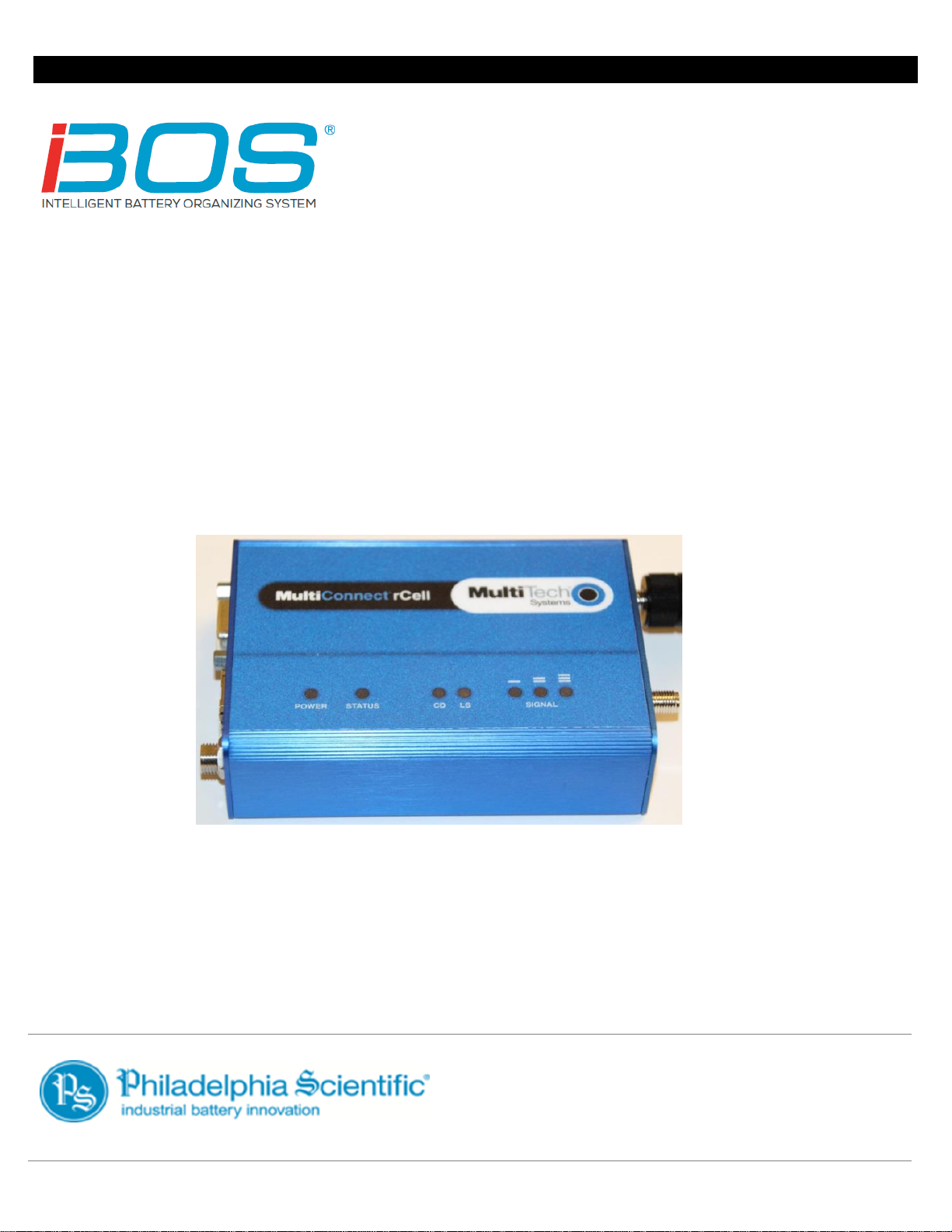
Philadelphia Scientific IBOS Cellular Modem User manual

DOC0052
September 2018
Version 1.3
Installation Manual
Cellular Modem

Philadelphia Scientific® Cellular Modem Installation Manual
Page 2 of 16
Table of Contents
Cellular Modem
1. Introduction..............................................................................................................................................3
1.1 System Overview...............................................................................................................................3
1.2 Organization of this Manual................................................................................................................3
1.3 Contact Information............................................................................................................................3
2. System Components................................................................................................................................4
2.1 Cellular Modem and Mounting Bracket...............................................................................................4
2.2 Power Supply.....................................................................................................................................4
2.3 Antenna .............................................................................................................................................4
2.4 Peripheral Data Cable........................................................................................................................4
2.5 Optional Antenna Extension...............................................................................................................4
2.6 Optional Signal Booster .....................................................................................................................5
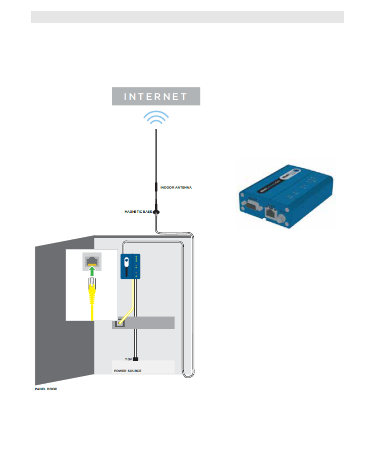
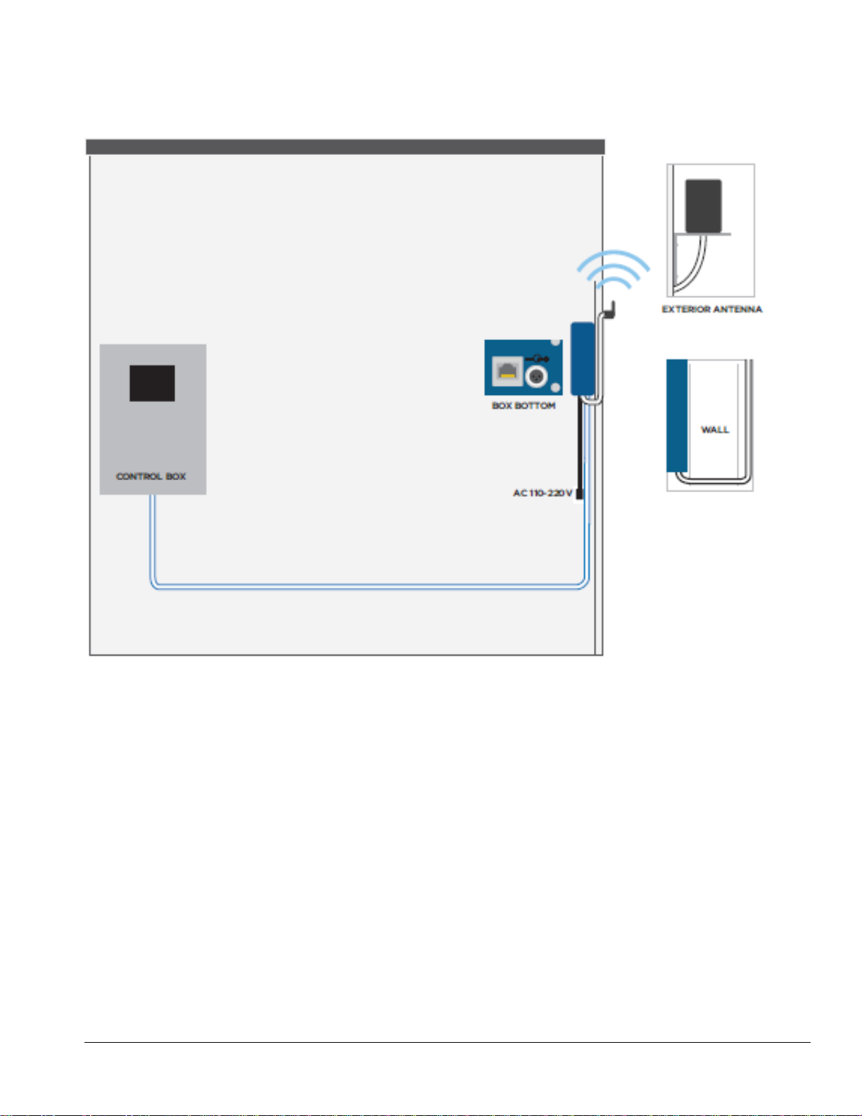
3. Diagram of Installation.............................................................................................................................6
Option 1: Cellular Modem Located Inside Control Box (iBOS®Pro 6 Series only)....................................6
Option 2: Cellular Modem Located Outside Control Box ..........................................................................7
Option 3: Cellular Modem Located Outside Control Box with Antennas Mounted Outdoors.....................8
4. Pre-Installation.........................................................................................................................................9
4.1 Tools..................................................................................................................................................9
4.2 Location.............................................................................................................................................9
4.3 Signal Strength ..................................................................................................................................9
5. Installation .............................................................................................................................................10
5.1 Option 1: Cellular Modem Located Inside Control Box (iBOS®Pro 6 Series only)...........................10
5.1.1 Mounting Bracket ......................................................................................................................10
5.1.2 Modem......................................................................................................................................10
5.1.3 Power Supply............................................................................................................................10
5.1.4 Ethernet Cable..........................................................................................................................10
5.1.5 Antenna.....................................................................................................................................11
5.2 Option 2: Cellular Modem Located Outside Control Box..................................................................11
5.2.1 Mounting Bracket ......................................................................................................................11
5.2.2 Modem......................................................................................................................................11
5.2.3 Power Supply............................................................................................................................11
5.2.4 Ethernet Cable..........................................................................................................................12
5.2.5 Antenna.....................................................................................................................................12
5.3 Option 3: Cellular Modem Located Outside Control Box with Antennas Mounted Outdoors ............12
5.3.1 Mounting Bracket ......................................................................................................................12
5.3.2 Modem......................................................................................................................................12
5.3.2 Antenna.....................................................................................................................................13
5.3.3 Ethernet Cable..........................................................................................................................13
5.3.4 Power Supply............................................................................................................................13
6. Final Inspection and Testing..................................................................................................................14
7. Troubleshooting.....................................................................................................................................15

Philadelphia Scientific® Cellular Modem Installation Manual
Page 3 of 16
1. Introduction
1.1 System Overview
This manual will give you all the information that you need to connect your iBOS®controller to a cellular
modem in order to connect to the Internet. An Internet connection is necessary to transmit data from the
iBOS®controller to iBOSworld.com where you can find valuable information regarding activity in your
battery changing area. An iBOSworld subscription is required.
There are three options for installation detailed in this manual. All three installation options are compatible
with the iBOS®Pro 6 Series control box while only the last two installation options (where the cellular
modem is located outside the control box) are compatible with the iBOS®Plus 6 Series control box.
1.2 Organization of this Manual
This manual has been divided into sections for each of the stages of an installation project:
•Section 2 –System components. This section is simply to help you get familiar with what the
various parts of the system are and what they look like.
•Section 3 –Diagrams for Installation
•Section 4 –Pre-installation. You have ordered the system and are ready to go on the installation
trip. The steps in this section are invaluable in preparation for when you are on site. Our goal is that
you only need to make one trip to complete the installation.
•Section 5 –Installing the hardware. Finally, the actual installation steps to get everything mounted
and wired.
•Section 6–Final Inspection and testing
•Section 7–Troubleshooting
1.3 Contact Information
Philadelphia Scientific LLC
207 Progress Drive
Montgomeryville, PA 18936
USA
Phone: 215-616-0390
Fax: 215-616-0500
Philadelphia Scientific UK Ltd.
Atlas Mill
Bolton BL14LB
United Kingdom
Phone: +44 (0) 1204-467777
Fax: +44 (0) 1204-493300
Email: Info@ps-europe.net
Philadelphia Scientific-
Asia/Pacific
2/17 Norman Street
NSW, 2225
Australia
Phone: +61 2 8004-2447
Fax: +61 2 9012-0383

Philadelphia Scientific® Cellular Modem Installation Manual
Page 4 of 16
2. System Components
2.1 Cellular Modem and Mounting Bracket
The cellular modem transmits data from the
iBOS®controller through the Internet via
broadband cellular to iBOSworld.com.
2.2 Power Supply
The power supply provides power to the
cellular modem.
2.3 Antenna
The antenna connects to the modem and
transmits data to the cellular network.
2 x
2.4 Peripheral Data Cable
The peripheral data cable connects the
Ethernet port on the iBOS®controller to the
Ethernet port on the cellular modem.
A 50’ (15.2 m) cable is used when the
modem is located outside of the control
box, and a 6’ (1.8 m) or shorter cable is
used when the modem is located inside or
near the control box.
2.5 Optional Antenna Extension
Optional antenna extension BOS-163 used
to locate the antenna to a position with a
stronger signal.

Philadelphia Scientific® Cellular Modem Installation Manual
Page 5 of 16
2.6 Optional Signal Booster
Optional signal booster BOS-218 used in
locations with weak cellular service.

Philadelphia Scientific® Cellular Modem Installation Manual
Page 6 of 16
3. Diagram of Installation
Option 1: Cellular Modem Located Inside Control Box (iBOS®Pro 6
Series only)

Philadelphia Scientific® Cellular Modem Installation Manual
Page 7 of 16
Option 2: Cellular Modem Located Outside Control Box

Philadelphia Scientific® Cellular Modem Installation Manual
Page 8 of 16
Option 3: Cellular Modem Located Outside Control Box with
Antennas Mounted Outdoors

Philadelphia Scientific® Cellular Modem Installation Manual
Page 9 of 16
4. Pre-Installation
These are items that should be done before installation begins.
4.1 Tools
There are a few tools that are needed for the installation:
•Drill & Bits (depending on where the cellular modem is mounted)
•Anchors (suitable for the length and modem mounting surface)
•Phillips Head Screw Driver (for opening the iBOS®Pro 6 Series controller)
4.2 Location
•Choose a location to mount the cellular modem in a safe area that will be free from hazards.
•Mount it in a secure area where it is not easily accessible if possible.
•Choose a surface to mount the modem where anchors can be used.
4.3 Signal Strength
The standard modem uses Verizon
Wireless Service to upload iBOS®event
data. You can verify a good signal is
available using any Verizon based phone. If
no signal is available in the battery room,
mount the antennas outdoors or install the
optional signal booster to improve
reception.
If you do not have Verizon coverage in the location but do have AT&T, you’ll need to special order the
modem. Global coverage by Vodafone is also available.
Note: Additional charges for cellular service are required.
Note: AC Power (110-240 VAC / 50-60 Hz) is required to power the cellular modem and must be available
at the location where Cellular Modem will be installed.

Philadelphia Scientific® Cellular Modem Installation Manual
Page 10 of 16
5. Installation
5.1 Option 1: Cellular Modem Located Inside Control Box (iBOS®
Pro 6 Series only)
5.1.1 Mounting Bracket
Slide the cellular modem mounting bracket
into the slot on the back of the modem.
5.1.2 Modem
Mount the cellular modem inside the control
box.
5.1.3 Power Supply
Connect the power supply to the modem
and plug the power supply into a 110 or
240V (50-60Hz) receptacle or a UPS inside
the control box, if available.
5.1.4 Ethernet Cable
Connect the 6’ (1.8 m) Ethernet cable to
the Ethernet port on the cellular modem.
Connect the other end of the Ethernet
cable to the Ethernet port on the iBOS®
controller.

Philadelphia Scientific® Cellular Modem Installation Manual
Page 11 of 16
5.1.5 Antenna
Place the antennas on top of the control
box and route the antenna cables through
the hole in the bottom of the control box.
Connect the antenna cables to the CELL
and AUX connectors on the cellular
modem.
(Do not drill holes in the top of the control
box.)
5.2 Option 2: Cellular Modem Located Outside Control Box
5.2.1 Mounting Bracket
Slide the cellular modem mounting bracket
into the slot on the back of the modem.
5.2.2 Modem
Mount the cellular modem in a location
outside of the control box where 110 or
240V (50-60Hz) power is provided and the
cellular modem has a signal.
(It is desirable to have at least two bars for
strong communications.)
5.2.3 Power Supply
Connect the power supply to the modem
and plug the power supply into a 110 or
240V (50-60Hz) receptacle.
110-240 V (50-60Hz)

Philadelphia Scientific® Cellular Modem Installation Manual
Page 12 of 16
5.2.4 Ethernet Cable
Connect the 50’ (15.2 m) peripheral data
cable to the modem. Route the cable
through the hole in the bottom of the control
box and plug the cable into the controller’s
Ethernet port.
5.2.5 Antenna
Mount the antennas on an appropriate
surface and connect the antenna cables to
the CELL and AUX connectors on the
cellular modem
5.3 Option 3: Cellular Modem Located Outside Control Box with
Antennas Mounted Outdoors
5.3.1 Mounting Bracket
Slide the cellular modem mounting bracket
into the slot on the back of the modem.
5.3.2 Modem
Mount the cellular modem in a location
outside of the control box on an outside
wall where 110 or 240V (50-60Hz) power is
provided.
110-240 V (50-60Hz)
110-240 V (50-60Hz)

Philadelphia Scientific® Cellular Modem Installation Manual
Page 13 of 16
5.3.2 Antenna
Mount the antennas to the outside of the
building as high as possible. Route the
antenna cables through the wall and
connect them to the CELL and AUX
connectors on the cellular modem.
5.3.3 Ethernet Cable
Connect the 50’ (15.2 m) peripheral data
cable to the modem. If additional cable is
needed, up to 250’ (76.2 m) can be used,
but use the least amount necessary. Use
the couplers provided to connect the
cables. Route the cable through the hole in
the bottom of the control box and plug the
cable into the controller’s Ethernet port.
5.3.4 Power Supply
Connect the power supply to the modem
and plug the power supply into a 110 or
240V (50-60Hz) receptacle.
110-240 V (50-60Hz)

Philadelphia Scientific® Cellular Modem Installation Manual
Page 14 of 16
6. Final Inspection and Testing
Task
Status
Are all cable runs and connections for the communication cables secure?
Modem Top panel LED States
•Power
•Status
•CD
•LS
•Signal Strength
On
Flashing
On
On or Flashing
2 or 3 LED’s ON
Note: To improve Signal Strength, reorient or relocate the antennas until 3
LED’s stay on.
Modem Side panel LED State
•Right Ethernet LED Blinking or On
Does the iBOS®system upload to iBOSworld.com?
Reset the Maintenance screen to the default password (“11111”) or Settings
screen to the default password (“919191”) when leaving the box if it was
changed during installation.
Ensure that the Date and Time is set correctly.
Close the box and fasten the screws (locking is optional).

Philadelphia Scientific® Cellular Modem Installation Manual
Page 15 of 16
7. Troubleshooting
iBOS®controller does not upload to
iBOSworld.com
Be sure that DHCP Mode is selected on the Internet
Setup screen. See iBOS®Installation Manual,
DOC0023, for details.
Be sure that there is power to the modem and that it has
a signal.
Check that the Ethernet cable is connected to the
controller and the modem.
Check that the antenna connection is tight.
If there is no CD light illuminated, reboot the cell
modem. With the CD light on and at least two lights on
the signal strength, press Reboot under Internet
settings. Press Upload Now under Internet settings and
check Time Since Last Upload under Status.

Philadelphia Scientific® Cellular Modem Installation Manual
Page 16 of 16
© 2018 Philadelphia Scientific LLC. All Rights Reserved. Philadelphia Scientific, the PS logo and iBOS are registered trademarks
of Philadelphia Scientific LLC. iBOSworld and Real-Time Monitor are trademarks of Philadelphia Scientific. E&O.E.
Table of contents