Philips CVW300G2 User manual

Motors | Automation | Energy | Transmission & Distribution | Coatings
Variable Speed Drive for Electric Traction
Convertidor de Frecuencia para Tracción
Eléctrica
Inversor de Frequência para Tração Elétrica
CVW300G2
Installation Guide
Guía de Instalación
Guia de Instalação
Language: English, Spanish, Portuguese
All manuals and user guides at all-guides.com
all-guides.com

All manuals and user guides at all-guides.com

Installation Guide
Series: CVW300G2
Language: English
Document: 10005692328 / 00
Date: 06/2018
All manuals and user guides at all-guides.com

All manuals and user guides at all-guides.com

Summary
ABOUT THIS GUIDE.....................................................................................................................................7
SAFETY INSTRUCTIONS.............................................................................................................................7
CVW300G2 MAIN DESCRIPTION................................................................................................................7
RECEIVING AND STORAGE ........................................................................................................................7
MECHANICAL INSTALLATION ....................................................................................................................7
GENERAL MOUNTING CONSIDERATIONS................................................................................................7
ELECTRICAL INSTALLATION ......................................................................................................................8
POWER WIRING DIAGRAMS ......................................................................................................................8
CONTROL WIRING DIAGRAMS ..................................................................................................................9
BASIC CONNECTION FOR FIRST POWER-UP ..........................................................................................9
INTEGRAL KEYPAD – HMI ........................................................................................................................ 10
BEFORE ENERGIZING............................................................................................................................... 11
START-UP IN THE VECTOR CONTROL MODE WITH ENCODER ........................................................... 11
APPENDIX 1 – TECHNICAL SPECIFICATIONS......................................................................................... 12
All manuals and user guides at all-guides.com

All manuals and user guides at all-guides.com
all-guides.com

Variable Speed Drive for Electric Traction
English
CVW300G2 | 7
ABOUT THIS GUIDE
This guide shows how to install and how to start-up the CVW300G2
Variable Speed Drive in Encoder Vector Control Mode.
For detailed information please refer to the CVW300G2 user's manual.
It is also possible to operate the CVW300G2 in the following control
modes: Sensorless Vector Control and V/f Control for induction
motors. Please see the user's manual.
For information on other functions and communication, please check
on the WEG's website www.weg.net for downloading the manuals.
SAFETY INSTRUCTIONS
Fully read this guide before installing or operating the drive.
Only trained and qualified personnel should attempt to install, start-up
and troubleshoot this type of equipment. The personnel must follow
all the safety instructions described in this guide and/or defined by
the local regulations.
DANGER!
Failure to comply with the safety instructions may result
in death, serious injury and equipment damage. Always
disconnect the main power supply before touching any
electrical device associated to the drive.
Several components can remain charged even after
the battery has been disconnected or turned off. Wait
at least 10 minutes to assure the total discharge of
the capacitors.
DANGER!
Les procéduresconcernées par cetavertisse
mentsontdestinées à protéger l'utilisateur contre des
dangers mortels, des blessures et des détériorations
matérielles importantes. Débranchez toujours
l'alimentation principale avant d'entrer en contact avec
un appareil électrique associé au variateur.
Plusieurs composants peuvent rester chargés même
une fois que la batterie est débranchée ou mise
hors tension. Attendez au moins 10 minutes que les
condensateurs se déchargent complètement.
NOTE!
For the purpose of this guide, qualified personnel are
those trained and able to:
1. Install, ground, power-up, and operate the
CVW300G2 according to this guide and to the
current legal safety procedures.
2. Use the protection equipment according to the
established regulations.
3. Provide first aid.
NOTE!
The CVW300G2 may interfere with other electronic
equipment. Follow the installation instructions for
minimizing these effects.
CVW300G2 MAIN DESCRIPTION
The CVW300G2 Variable Speed Drive is a high performance product
with models in the peak power range from 2.2 to 16 kW and DC
voltages from 24 to 48 Vdc. It is designed for speed and torque
control of three-phase induction motors. The CVW300G2 Variable
Speed Drive has the control modes: Vector with Encoder, Vector
Sensorless and Scalar (Adjustable V/f).
NOTE!
In applications that involve motion and/or safety, the
use of the Encoder Vector Control is crucial.
For more detailed information refer to the CVW300G2 user's manual.
RECEIVING AND STORAGE
When receiving the product verify if:
The CVW300G2 nameplate data matches the purchase order. See
models and technical characteristic in Table A.12 on page 12.
Any damage occured during transportation. If any problem is
detected, contact the carrier immediately.
If the CVW300G2 is not to be installed immediately, store it in a
clean and dry place (storage temperatures between -25 °C (-13 °F)
and 60 °C (140 °F).
MECHANICAL INSTALLATION
ENVIRONMENT
Due to the CVW300G2's high protection degree (IP66), it can be
installed outdoors, even exposed to the weather.
GENERAL MOUNTING CONSIDERATIONS
Consult the inverter weight in Table A.12 on page 12.
Install the drive on a flat surface with good heat dissipation. It is
recommended the application of heatsink compound between the
inverter metallic baseplate and the installation surface in order to
help the heat transfer. It is also recommended some airflow on the
product plastic cover.
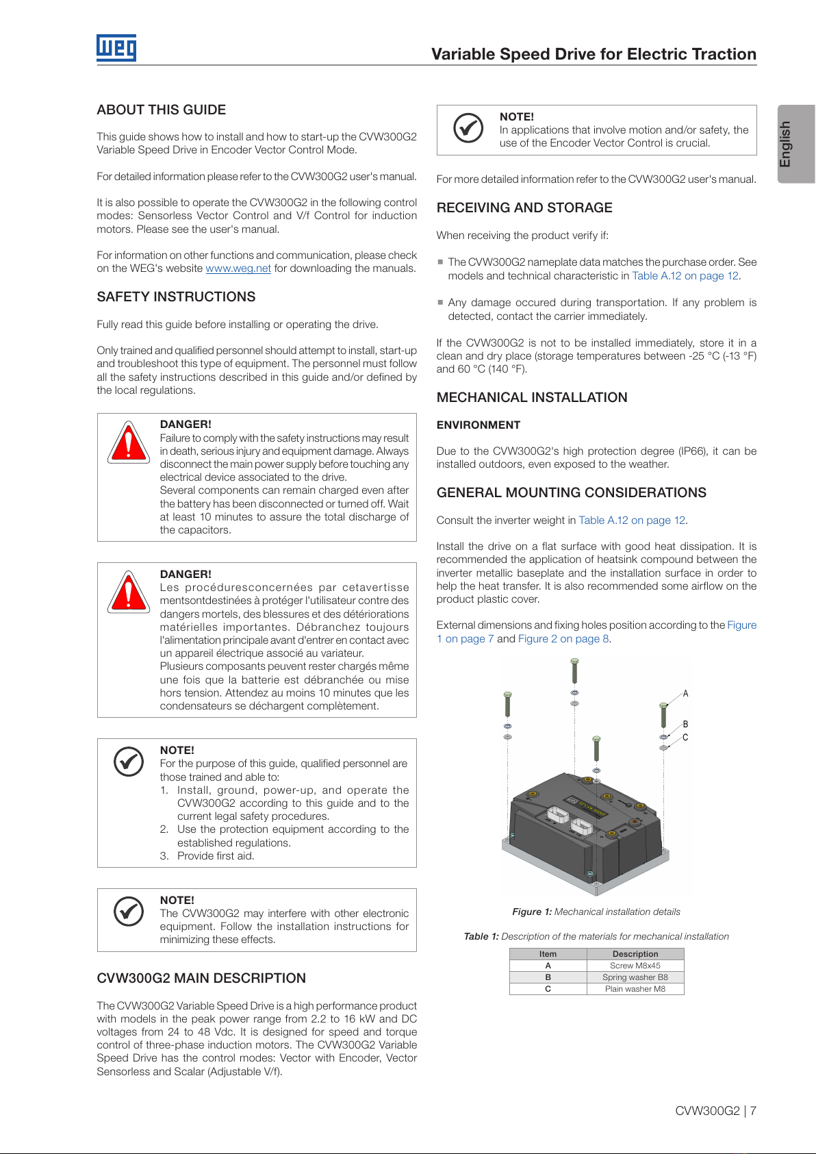
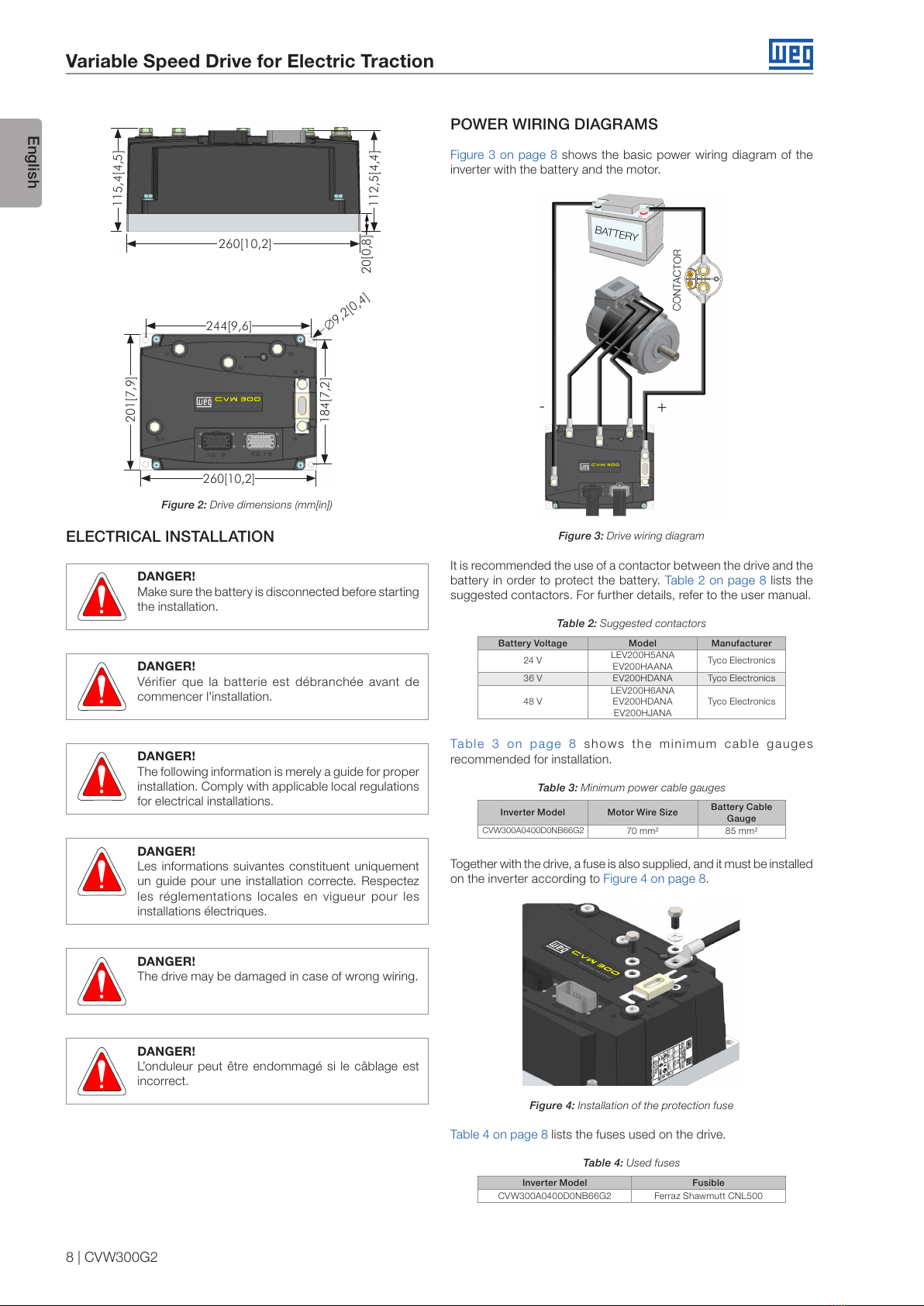
External dimensions and fixing holes position according to the Figure
1 on page 7 and Figure 2 on page 8.
Figure 1: Mechanical installation details
Table 1: Description of the materials for mechanical installation
Item Description
AScrew M8x45
BSpring washer B8
CPlain washer M8
All manuals and user guides at all-guides.com

Variable Speed Drive for Electric Traction
English
8 | CVW300G2
260[10,2]
20[0,8]
115,4[4,5]
112,5[4,4]
244[9,6]
260[10,2]
∅9,2[0,4]
201[7,9]
184[7,2]
Figure 2: Drive dimensions (mm[in])
ELECTRICAL INSTALLATION
DANGER!
Make sure the battery is disconnected before starting
the installation.
DANGER!
Vérifier que la batterie est débranchée avant de
commencer l'installation.
DANGER!
The following information is merely a guide for proper
installation. Comply with applicable local regulations
for electrical installations.
DANGER!
Les informations suivantes constituent uniquement
un guide pour une installation correcte. Respectez
les réglementations locales en vigueur pour les
installations électriques.
DANGER!
The drive may be damaged in case of wrong wiring.
DANGER!
L’onduleur peut être endommagé si le câblage est
incorrect.
POWER WIRING DIAGRAMS
Figure 3 on page 8 shows the basic power wiring diagram of the
inverter with the battery and the motor.
+-
Figure 3: Drive wiring diagram
It is recommended the use of a contactor between the drive and the
battery in order to protect the battery. Table 2 on page 8 lists the
suggested contactors. For further details, refer to the user manual.
Table 2: Suggested contactors
Battery Voltage Model Manufacturer
24 V LEV200H5ANA
EV200HAANA Tyco Electronics
36 V EV200HDANA Tyco Electronics
48 V
LEV200H6ANA
EV200HDANA
EV200HJANA
Tyco Electronics
Table 3 on page 8 shows the minimum cable gauges
recommended for installation.
Table 3: Minimum power cable gauges
Inverter Model Motor Wire Size Battery Cable
Gauge
CVW300A0400D0NB66G2 70 mm² 85 mm²
Together with the drive, a fuse is also supplied, and it must be installed
on the inverter according to Figure 4 on page 8.
Figure 4: Installation of the protection fuse
Table 4 on page 8 lists the fuses used on the drive.
Table 4: Used fuses
Inverter Model Fusible
CVW300A0400D0NB66G2 Ferraz Shawmutt CNL500
All manuals and user guides at all-guides.com

Variable Speed Drive for Electric Traction
English
CVW300G2 | 9
CONTROL WIRING DIAGRAMS
The CVW300G2 has two sealed connectors, XC9 and XC10, which
are used to wire control signals from the drive.
Figure 5: Identification of connectors XC9 and XC10
The functions of each terminal are listed in Table 5 on page 9
and Table 6 on page 9.
Table 5: Functions of terminals XC9
Terminal Signal
XC9 - 01 A-HMI HMI interface – RS-485
XC9 - 02 B-HMI
XC9 - 03 +15 V HMI power supply
XC9 - 04 DGND HMI reference
XC9 - 05 A RS-485 interface (PC)
XC9 - 06 B
XC9 - 07 CANH CAN interface(1)
XC9 - 08 CANL
XC9 - 09 +15 V* +15 V auxiliary (Protected)
XC9 - 10 DI3
Digital inputs
XC9 - 11 DI4
XC9 - 12 DI5
XC9 - 13 DI6
XC9 - 14 DI7
XC9 - 15 DI8
XC9 - 16 DO4 Digital outputs
XC9 - 17 DO5
XC9 - 18 AO1 Analog outputs
XC9 - 19 AO2
XC9 - 20 DGND Analog reference
XC9 - 21 PTC+ PTC inputs
XC9 - 22 PTC-
XC9 - 23 NC Not used
(1) In order to use the CAN interface, contact WEG.
Table 6: Functions of terminals XC10
Terminal Signal
XC10 - 01 +5 V_ENC 5 V Incremental encoder
power supply
XC10 - 02 A
Incremental encoder interface
XC10 - 03 A
XC10 - 04 B
XC10 - 05 B
XC10 - 06 Z
XC10 - 07 Z
XC10 - 08 DGND Incremental encoder reference
XC10 - 09 +15 V* +15 V aux (Protected) /
Encoder Supply
XC10 - 10 DO2 Digital outputs
XC10 - 11 DO3
XC10 - 12 AI1 Analog input # 1
XC10 - 13 AI2 Analog input # 2
XC10 - 14 REF+ Positive analog reference
XC10 - 15 REF- Negative analog reference
XC10 - 16 CONTACTOR Drive of the main contactor
XC10 - 17 UDA Electronics power supply
XC10 - 18 XCA Main contactor feedback
XC10 - 19 DI1 Digital inputs
XC10 - 20 DI2
XC10 - 21 DO1 (NC) Relay digital output (NC)
XC10 - 22 DO1 (NO) Relay digital output (NO)
XC10 - 23 DO1 (COM) Relay digital output (COM)
BASIC CONNECTION FOR FIRST POWER-UP
WEG motors used with the CVW300G2 are supplied with a speed
sensor (encoder), and it must be connected to the CVW300G2 for
the reading of the signals according to Table 7 on page 9.
Table 7: Encoder wiring diagram
Encoder Wires CVW300G2
Red XC10 pin 9
Yellow XC10 pin 2
Green XC10 pin 4
Blue XC10 pin 6
Black XC10 pin 8
NOTE!
In order to connect the encoder to the CVW300G2,
you must additionally short XC10 pins 3, 5 and 7,
together with XC10 pin 8. The WEG´s encoder supply
is done by the +15 V aux power supply, in XC10
connector, pin 9.
When present, the HMI Interface must be connected to the
CVW300G2 by means of a shielded cable with a female DB9 terminal,
according to Table 8 on page 9.
Table 8: HMI wiring diagram
Female DB9 Connector CVW300G2
1 -
2 XC9 pin 1
3 XC9 pin 1
4 XC9 pin 4
5 XC9 pin 3
6 XC9 pin 4
7 XC9 pin 2
8 XC9 pin 2
9 -
In order to purchase a HMI accessory, refer to the user manual.
Most electric drive applications need an accelerator. It is
recommended to use electronic accelerators with potentiometer
with minimum impedance of 2 kΩ and with the wiring suggested in
Figure 6 on page 9.
XC10 Pin 14
XC10 Pin 12
XC10 Pin 8
Figure 6: Accelerator wiring
All manuals and user guides at all-guides.com

Variable Speed Drive for Electric Traction
English
10 | CVW300G2
In case the contactor used between the CVW300G2 and the battery
has an auxiliary contact, its wiring must be done according to Figure
7 on page 10.
XC10 Pin 18
XC10 Pin 16
Figure 7: Contactor wiring
NOTE!
In case the contactor does not have an auxiliary
contact, it is necessary to short the pins 17 and 18
of XC10; otherwise, the inverter will show fault F185.
INTEGRAL KEYPAD – HMI
The HMI for the CVW300G2 is supplied as an accessory and must
be purchased separately. For detailed information please refer to the
CVW300G2 user's manual.
- Press this key to accelerate the motor up to the speed set in P0122. The motor
speed is maintained while the key is pressed. When the key is released the
motor decelerates up to its complete stop.
This function is active when all the following conditions are met:
1. Start/Stop = Stop.
2. General Enable = Active.
3. P0225 = 1 in LOC and/or P0228 = 1 in REM.
1. Press this key to
decrease the speed.
2. Press this key to go to
the next group.
3. Press this key to go
back to the previous
parameter.
4. Press this key
to decrease the
parameter value.
1. Press this key to enter
in the programming
mode.
2. Press this key to select
the desired parameter
group.
3. Press this key to show
the parameter.
4. Press this key to save
the parameter value.
- Press this key to
accelerate the motor
according to the
acceleration ramp time.
This option is active
when:
P0224 = 0 in LOC and/or
P0227 = 0 in REM.
- Press this key to
decelerate the motor
according to the
deceleration ramp time.
This option is active
when:
P0224 = 0 in LOC and/or
P0227 = 0 in REM.
1. Press this key to go
back to the previous
group.
2. Press this key to go to
the next parameter.
3. Press this key
to increase the
parameter value.
- USB communication
port
1. Press this key to
go back to the
monitoring mode.
2. Press this key to
go back to the
previous level in the
parameterization
mode.
3. Press this key to
cancel the new value
and go back to the
previous level.
- Press this key to
define the motor
rotation.
This option is active
when:
P0223 = 2 or 3 in
LOC and/or
P0226 = 2 or 3 in
REM.
- Press this key to
toggle between
LOCAL and REMOTE
mode.
This option is active
when:
P0220 = 2 or 3.
Figure 8: Operator keys
NOTE!
It is necessary to set the password at P0000 for
parameter modification; otherwise the parameters
contents can only beviewed.
The default password for P0000 is 5. It is possible
to change the password at P0200. Refer to the
CVW300G2 user's manual.
Inverter
status
Local/Remote
(commands and
references source)
Motor
rotation
Secondary
display
Variable
unit (shows
the value
of the main
display)
Variable
monitoring
bar graph
Menu
(parameters
group
selection)
– only one
parameter
group is
shown
ateach time.
Main display
Figure 9: Display sections
Parameter groups available at the Menu:
PARAM: all parameters.
READ: only the reading parameters.
MODIF: only the parameters changed compared to the factory
default.
BASIC: basic application parameters.
MOTOR: parameters related to motor data control.
I/O: parameters related to the digital and analog inputs/outputs.
NET: parameters related to the communication protocol.
HMI: parameters for the keypad configuration.
SPLC: parameters related to the SoftPLC function.
STARTUP: parameters for the oriented startup.
Inverter status:
LOC: command source or local reference.
REM: command source or remote reference.
:motor rotation according to the arrows.
CONF: configuration. It indicates that the inverter is in the Oriented
Start-up routine or with in compatible parameter programming.
Refer section 5.6 Incompatibility Between Parameters in the user's
manual of the CVW300G2.
SUB: Battery undervoltage.
RUN: inverter enabled and/or DC braking activated.
All manuals and user guides at all-guides.com

Variable Speed Drive for Electric Traction
English
CVW300G2 | 11
START-UP IN THE VECTOR CONTROL MODE WITH
ENCODER
The “Oriented Start-up” routine presents on the keypad (HMI) the main
parameters in a logical sequence. The setting of these parameters
prepares the drive for operation with the battery and motor of the
application. Verify the step by step sequence in the Figure 11 on
page 12.
The setting of the parameters presented in this operation mode
results in the automatic modification of the content of other drive
parameters and/or internal variables, as indicated in the Figure 11
on page 12. In this way one gets a stable operation of the control
circuit with adequate values to obtain the best motor performance.
During the “Oriented Start-up” routine the “Config” (Configuration)
status will be indicated on the keypad (HMI).
Parameters related to the motor:
Program the content of parameters P0398, P0400 to P0406
directly with the motor nameplate data.
Options for the setting of parameters P0409 to P0412:
- Automatic by the inverter, performing the self-tuning routine
selected in P0408.
- From the motor test data sheet, supplied by the manufacturer.
- Manually, copying the parameters content of another CVW300G2
which uses an identical motor.
Setting of specific parameters and functions for the
application:
Program the digital and analog inputs and outputs, HMI keys, etc.,
according to the application needs.
For applications:
That require only the digital and analog inputs and outputs with
programming different from the factory settings, use the Menu
“I/O”.
That need functions as Flying Start,DC Braking, etc., access
and modify those functions parameters by means of the Menu
“PARAM”.
Monitoring Mode
It is the initial state of the keypad after power
up and startup screen, with the factory default
values.
The Menu is not active in this mode.
Main display, secondary display and monitoring
bar show the values of the parameters defined
at P0205, P0206 and P0207.
From the monitoring mode, pressing the ENTER/
MENU key will switch to the programming mode.
Parameterization Mode
Level 1:
This is the first level of the programming mode.
It is possible to chose the parameter group by
using the and keys.
The main display, secondary display, bar graph
to monitor variable and unit of measurement are
not shown at this level.
Press the ENTER/MENU key to go to the second
level of programming mode - parameters
selection.
Press the BACK/ESC key to go back to the
monitoring mode.
Level 2:
The parameter number is displayed on the main
display and its value on the secondary display.
Use the and keys to find the desired
parameter.
Press the ENTER/MENU key to go to level 3
of the programming mode – parameters value
changing.
Press the BACK/ESC key to return to level 1 of
the programming mode.
Level 3:
The parameter values is shown at the main
display and the parameter number at the
secondary display.
Use the and keys to change the value
of the selected parameter.
Press ENTER/MENU key to confirm the
modification (save the new value) or BACK/ESC
key to cancel the modification (do not save the
new value). In both cases, the keypad returns
to the second level of the programming mode.
Figure 10: Keypad operation modes
Notes on Keypad:
The HMI can be connected with the drive energized.
Other monitoring screen types can be programmed, as bar
graphs and larger font sizes, through P0205-207 and P0208-212
adjustments.
A list of parameters is supplied with the product, for additional
information on each parameter refer to the CVW300G2 user´s manual
that can be downloaded at the WEG homepage - www.weg.net.
BEFORE ENERGIZING
1. Check if power and control connections are correct and firmly
secured.
2. Verify the motor connections and if its voltage and current fit with
the drive rated values.
3. Mechanically uncouple the motor from the load. If the motor
cannot be uncoupled, make sure that any speed direction (forward
or reverse) will not result in personnel injury and/or equipment
damage.
4. Measure the power supply voltage and verify if it is with in the
allowed range.
5. Apply power to the input.
6. Check the result of the first time power-up:
The status LED should be steady green.
All manuals and user guides at all-guides.com
all-guides.com

Variable Speed Drive for Electric Traction
English
12 | CVW300G2
Seq. Action/Result Display Indication
12
-If necessary, change “P0401 – Motor
Rated Current” ” parameter. This change
will affect P0156, P0157, P0158 and P0410.
-Press the key to the next parameter.
13
-If necessary, change “P0404 – Motor
Rated Power” parameter. This change
will affect P0410.
-Press the key to the next parameter.
14
-If necessary, change “P0403 – Motor
Rated Frequency” parameter. This
change will affect P0402.
-Press the key to the next parameter.
15
-If necessary, change “P0402 – Motor
Rated Speed”. This change will affect
P0122 to P0131, P0135, P0182, P0208,
P0288 and P0289.
-Press the key to the next parameter.
16
-If necessary, change “P0405 – Encoder
Pulses Number” according to the
encoder model.
-Press the key to the next parameter.
17
-In this moment the keypad presents
the option to perform “Self-tunning”.
The Self-tunning should be performed
whenever it is possible. Press “ENTER/
MENU” key to access parameter P0408
and press to select the desired
option. Then, press “ENTER/MENU”
to start the Self-tunning. The keypad
will show “CONF” and “RUN”status
simultaneously during the self-tunning.
At the end of the self-tuning, the “RUN”
status is automatically erased and the
content of P0408 automatically goes
back to the.
18
-Press BACK/ESC key to finish the
start-up routine.
-Press BACK/ESC key again to get back
to the monitoring mode.
Figure 11: Start-up Oriented to the vector mode
APPENDIX 1 – TECHNICAL SPECIFICATIONS
Table A.12: Technical specifications of CVW300G2 model
Model CVW300A0400D0NB66G2
Input rated voltage 24...48 V
Input voltage limits 18...66 V
Output rated current 40 °C 200 A
50 °C 200 A
Peak output current 400 A
Output voltage Vcc
2
√
Dissipated power Rated 300 W
Peak 910 W
Weight 5,9 kg
Environment temperature -25...50°C (-13...122°F)
Seq. Action/Result Display Indication
1
-Monitoring mode.
-Press the ENTER/MENU key to get in to
the first level of the programming mode.
2
-The PARAM group is selected, press the
or keys to select the STARTUP
group.
3-Press ENTER/MENU when the group is
selected.
4
-The parameter “P0317 – Oriented
Startup” is then selected, press the
ENTER/MENU to get into the parameter
content.
5-Change the parameter P0317 to “1 – Yes”,
using the key.
6-When the desired value is reached press
ENTER/MENU to save.
7
-In this moment the Oriented Start-
uproutine is initiated and the “CONF”
status is indicated at the keypad (HMI).
-The parameter “P0000 – Access to
Parameters” is selected. Change the
password to set the remaining parameters
if necessary.
-Press the key to the next parameter.
8
-If necessary, change “P0296 – Battery
Rated Voltage”. This change will affect
P0151, P0185, and P0400.
-Press the key to the next parameter.
9
-Set parameter “P0202 – Typeof Control”
pressing “ENTER/MENU”. Press the
key to select the desired option: “[1] =
Sensorless” or “[2] = Encoder”.This
modification resets the content of P0410.
Then, press “ENTER/MENU”. There are
three options to exit the oriented start-up:
1 - Running the Self-tunning.
2 - Manual settings of parameters from
P0409 to P0413.
3 - Changing P0202 from vector to scalar.
-Press the key to the next parameter.
10
-If necessary, change “P0398 – Motor
Service Factor” parameter. This change
will affect the current and the time of the
motor overload protection operation.
-Press the key to the next parameter.
11
-If necessary, change “P0400 – Motor
Rated Voltage” parameter. This change
corrects the output voltage by the factor
“x = P0400/ P0296”.
-Press the key to the next parameter.
All manuals and user guides at all-guides.com

Guía de Instalación
Serie: CVW300G2
Idioma: Español
Documento: 10005692328 / 00
Data: 06/2018
All manuals and user guides at all-guides.com

All manuals and user guides at all-guides.com

Índice
SOBRE LA GUÍA......................................................................................................................................... 17
INSTRUCCIONES DE SEGURIDAD........................................................................................................... 17
DESCRIPCIÓN PRINCIPAL DEL CVW300G2 ........................................................................................... 17
RECEPCIÓN Y ALMACENAMIENTO......................................................................................................... 17
INSTALACIÓN MECÁNICA......................................................................................................................... 17
CONSIDERACIONES GENERALES DE MONTAJE................................................................................... 17
INSTALACIÓN ELÉCTRICA........................................................................................................................ 18
DIAGRAMAS DE CONEXIÓN DE POTENCIA ........................................................................................... 18
DIAGRAMAS DE CONEXIÓN DE CONTROL ............................................................................................ 19
CONEXIÓN BÁSICA PARA PRIMERA ENERGIZACIÓN........................................................................... 19
INTERFAZ HOMBRE-MÁQUINA HMI........................................................................................................20
ANTES DE LA ENERGIZACIÓN.................................................................................................................21
PUESTA EN FUNCIONAMIENTO EN MODO DE CONTROL VECTORIAL CON ENCODER ..................21
APENDICE 1 – ESPECIFICACIONES TÉCNICAS......................................................................................22
All manuals and user guides at all-guides.com

Índice
All manuals and user guides at all-guides.com
all-guides.com

Convertidor de Frecuencia para Tracción Eléctrica
Español
CVW300G2 | 17
SOBRE LA GUÍA
Esta guía presenta cómo instalar y poner en funcionamiento, en
modo de control vectorial con encoder, el convertidor de frecuencia
CVW300G2.
Para obtener más detalles sobre el convertidor de frecuencia
CVW300G2, consulte el manual del usuario.
También es posible operar el CVW300G2 en los modos de control:
Control Vectorial Sensorless y V/f para motores de inducción.
Consulte el manual del usuario.
Para obtener los manuales en formato electrónico, así como
informaciones sobre otras funciones y condiciones de funcionamiento,
consulte el sitio WEG - www.weg.net.
INSTRUCCIONES DE SEGURIDAD
Lea totalmente esta guía antes de instalar u operar el convertidor.
Solamente personas con calificación adecuada y familiaridad con
el convertidor CVW300G2 y equipos asociados podrán planear o
implementar la instalación, arranque, operación y mantenimiento de
este equipo. Estas personas deberán seguir todas las instrucciones
de seguridad contenidas en este manual y/o definidas por normas
locales.
¡PELIGRO!
Los procedimientos recomendados en este
aviso tienen como objetivo proteger al usuario
contra muerte, heridas graves o daños materiales
considerables. Siempre desconecte la alimentación
general antes de tocar cualquier componente
eléctrico asociado al convertidor.
Muchos componentes pueden permanecer cargados,
incluso después de que la batería sea desconectada
o apagada. Aguarde por lo menos 10 minutos para
garantizar la total descarga de los condensadores.
¡NOTA!
Para un mejor entendimiento, personas calificadas son
las capacitadas, estando aptas para:
1. Instalar, poner a tierra, energizar y operar el
CVW300G2 de acuerdo con este manual y con
los procedimientos legales de seguridad vigentes.
2. Utilizar los equipos de protección de acuerdo con
las normas establecidas.
3. Prestar servicios de primeros auxilios.
¡NOTA!
Los convertidores de frecuencia pueden interferir en
otros equipos electrónicos. Siga las instrucciones de
instalación para minimizar tales efectos.
DESCRIPCIÓN PRINCIPAL DEL CVW300G2
El convertidor de frecuencia CVW300G2 es un producto de alto
desempeño con modelos que atienden el rango de potencia de
2.2 a 16 kW de pico y tensión de alimentación de 24 a 48 Vcc. Fue
desarrollado para el control de velocidad y torque de motores de
inducción trifásicos. El convertidor de frecuencia CVW300G2 cuenta
con los modos de control: Vectorial con Encoder, Vectorial Sensorless
y Escalar (V/f Ajustable).
¡NOTA!
En aplicaciones que impliquen movimiento y/o
seguridad, es imprescindible la utilización del modo
de control Vectorial con Encoder.
Para más detalles consulte el manual del usuario del CVW300G2.
RECEPCIÓN Y ALMACENAMIENTO
Cuando reciba el producto verifique si:
La etiqueta de identificación del CVW300G2 corresponde al
modelo comprado. Consulte el modelo y las características
técnicas en la Tabla A.9 en la página 22.
Ocurrieron daños durante el transporte. En caso de que
sea detectado algún problema, contacte inmediatamente la
transportadora.
Si el CVW300G2 no es instalado enseguida, almacénelo en un lugar
limpio y seco (temperatura entre -25 °C y 60 °C).
INSTALACIÓN MECÁNICA
CONDICIONES AMBIENTALES
Por contar con un grado de protección IP66, el CVW300G2 puede ser
instalado en ambientes externos e inclusive expuesto a intemperies.
CONSIDERACIONES GENERALES DE MONTAJE
Consulte el peso del convertidor en la Tabla A.9 en la página 22.
Instale el convertidor en una superficie plana, con buena disipación
de calor. Se recomienda la aplicación de pasta térmica entre la base
metálica del convertidor y la superficie de instalación del producto,
de forma de auxiliar en el intercambio de calor del producto. Así
mismo, es recomendable la circulación de aire en la tapa plástica
del producto.
Dimensiones externas y posición de los agujeros de fijación conforme
la Figura 1 en la página 17 y la Figura 2 en la página 18.
Figura 1: Detalles para instalación mecánica
Tabla 1: Descripción de los materiales para fijación mecánica
Ítem Descripción
ATornillo M8x45
BArandela de presión B8
CArandela lisa M8
All manuals and user guides at all-guides.com

Convertidor de Frecuencia para Tracción Eléctrica
Español
18 | CVW300G2
260[10,2]
20[0,8]
115,4[4,5]
112,5[4,4]
244[9,6]
260[10,2]
∅9,2[0,4]
201[7,9]
184[7,2]
Figura 2: Dimensionales del producto
INSTALACIÓN ELÉCTRICA
¡PELIGRO!
Asegúrese de que la batería esté desconectada,
antes de iniciar la instalación.
¡PELIGRO!
Las informaciones a seguir tienen la intención de
servir como guía para, de esta forma, obtenerse
una instalación correcta. Siga también las normas
aplicables de instalación eléctrica.
¡PELIGRO!
El convertidor podrá ser dañado en caso de que las
conexiones sean hechas de forma correcta.
DIAGRAMAS DE CONEXIÓN DE POTENCIA
En la Figura 3 en la página 18 está demostrado el diagrama básico
de conexión de potencia del convertidor con la batería y el motor.
CONTACTOR
BATERÍA
+-
Figura 3: Esquema de conexión del convertidor
Se recomienda la utilización de un contactor entre el convertidor y
la batería, de modo de protegerla. La relación de los contactores
sugeridos está en la Tabla 2 en la página 18. Para más detalles,
consulte el manual del usuario.
Tabla 2: Contactores sugeridos
Tensión de la Batería Modelo Fabricante
24 V LEV200H5ANA
EV200HAANA Tyco Electronics
36 V EV200HDANA Tyco Electronics
48 V
LEV200H6ANA
EV200HDANA
EV200HJANA
Tyco Electronics
En la Tabla 3 en la página 18 están detallados los calibres mínimos
recomendados para instalación.
Tabla 3: Calibres mínimos de los cables de potencia
Modelo de Convertidor Calibre de los Cables
del Motor
Calibre de los Cables
de la Batería
CVW300A0400D0NB66G2 70 mm² 85 mm²
Con el convertidor es suministrado un fusible, que debe ser montado
en éste, conforme la Figura 4 en la página 18.
Figura 4: Conexión del fusible de protección
Los fusibles utilizados en el convertidor están relacionados en la
Tabla 4 en la página 18.
Tabla 4: Fusibles utilizados
Modelo de Convertidor Fusible
CVW300A0400D0NB66G2 Ferraz Shawmutt CNL500
All manuals and user guides at all-guides.com

Convertidor de Frecuencia para Tracción Eléctrica
Español
CVW300G2 | 19
DIAGRAMAS DE CONEXIÓN DE CONTROL
El CVW300G2 posee dos conectores, XC9 y XC10, sellados, que son
utilizados para la conexión de las señales de control del convertidor.
CONECTOR XC9 CONECTOR XC10
Figura 5: Identificación de los conectores XC9 y XC10
Las funciones de cada terminal están relacionadas en la Tabla 5 en
la página 19 y en la Tabla 6 en la página 19.
Tabla 5: Funciones de los terminales XC9
Terminal Señal
XC9 - 01 A-HMI Interfaz HMI – RS-485
XC9 - 02 B-HMI
XC9 - 03 +15 V Alimentación de la HMI
XC9 - 04 DGND Referencia de la HMI
XC9 - 05 A Interfaz RS-485 (PC)
XC9 - 06 B
XC9 - 07 CANH Interfaz CAN(1)
XC9 - 08 CANL
XC9 - 09 +15 V* +15 V auxiliar (Protegido)
XC9 - 10 DI3
Entradas digitales
XC9 - 11 DI4
XC9 - 12 DI5
XC9 - 13 DI6
XC9 - 14 DI7
XC9 - 15 DI8
XC9 - 16 DO4 Salidas digitales
XC9 - 17 DO5
XC9 - 18 AO1 Salidas analógicas
XC9 - 19 AO2
XC9 - 20 DGND Referencia analógica
XC9 - 21 PTC+ Entradas del PTC
XC9 - 22 PTC-
XC9 - 23 NC No utilizado
(1) Para utilización de la interfaz CAN, contactar a WEG.
Tabla 6: Funciones de los terminales XC9
Terminal Señal
XC10 - 01 +5 V_ENC Alimentación 5 V del encoder
incremental
XC10 - 02 A
Interfaz del encoder
incremental
XC10 - 03 A
XC10 - 04 B
XC10 - 05 B
XC10 - 06 Z
XC10 - 07 Z
XC10 - 08 DGND Referencia del encoder
incremental
XC10 - 09 +15 V* +15 V aux (Protegido) /
Alimentación del encoder
XC10 - 10 DO2 Salidas digitales
XC10 - 11 DO3
XC10 - 12 AI1 Entrada analógica 1
XC10 - 13 AI2 Entrada analógica 2
XC10 - 14 REF+ Referencia analógica positiva
XC10 - 15 REF- Referencia analógica negativa
XC10 - 16 CONTATOR Accionamiento del contactor
principal
XC10 - 17 UDA Alimentación de la electrónica
XC10 - 18 XCA Feedback del contactor
principal
XC10 - 19 DI1 Entradas digitales
XC10 - 20 DI2
XC10 - 21 DO1 (NF) Salida digital a relé (NF)
XC10 - 22 DO1 (NA) Salida digital a relé (NA)
XC10 - 23 DO1 (COM) Saída digital a relé (COM)
CONEXIÓNBÁSICAPARAPRIMERAENERGIZACIÓN
Los motores WEG utilizados con el CVW300G2, son suministrados
con un sensor de velocidad (encoder). Dicho sensor deberá ser
conectado en el CVW300G2 para la lectura de las señales, conforme
la Tabla 7 en la página 19.
Tabla 7: Diagrama de conexión del encoder
Alambres del Encoder CVW300G2
Rojo XC10 terminal 9
Amarillo XC10 terminal 2
Verde XC10 terminal 4
Azul XC10 terminal 6
Negro XC10 terminal 8
¡NOTA!
Para la conexión del encoder en el CVW300G2
se debe, adicionalmente, cortocircuitar el XC10
terminales 3, 5 y 7, junto a XC10 terminal 8. La
alimentación del encoder WEG es hecho através de
la fuente +15V aux, en el terminal 9 del conector XC10.
Cuando presente, el accesorio HMI Interfaz Hombre-Máquina debe
ser conectado al CVW300G2 a través de un cable blindado, con
terminación DB9 hembra, conforme la Tabla 8 en la página 19.
Tabla 8: Diagrama de conexión de la HMI
Conector DB9 Hembra CVW300G2
1 -
2 XC9 terminal 1
3 XC9 terminal 1
4 XC9 terminal 4
5 XC9 terminal 3
6 XC9 terminal 4
7 XC9 terminal 2
8 XC9 terminal 2
9 -
Para adquirir un accesorio HMI, favor consulte el manual del usuario.
La gran mayoría de las aplicaciones de tracción eléctrica necesita
la utilización de un acelerador, se recomienda utilizar aceleradores
electrónicos a potenciómetro con impedancia mínima de 2 kΩ y con
conexión sugerida conforme la Figura 6 en la página 19.
XC10 terminal 14
XC10 terminal 12
XC10 terminal 8
Figura 6: Conexión del acelerador
All manuals and user guides at all-guides.com

Convertidor de Frecuencia para Tracción Eléctrica
Español
20 | CVW300G2
En caso de que el contactor utilizado entre el CVW300G2 y la batería
posea un contacto auxiliar, su conexión deberá ser hecha conforme
la Figura 7 en la página 20.
XC10 Terminal 18
XC10 Terminal 16
Figura 7: Conexión del contactor
¡NOTA!
En caso de que el contactor utilizado no posea
contacto auxiliar, será necesario cortocircuitar los
terminales 17 y 18 de XC10, en caso contrario el
convertidor indicará falla F185.
INTERFAZ HOMBRE-MÁQUINA HMI
La HMI para el CVW300G2 es suministrada como un accesorio y
debe ser adquirida separadamente. Para más detalles, consulte el
manual del usuario.
Acelera el motor hasta la velocidad ajustada en P0122. La velocidad del motor
será mantenida mientras la tecla esté presionada. Cuando la tecla sea liberada,
el motor será desacelerado hasta su parada. Esta función estará activa
cuando todas las condiciones de abajo sean cumplidas:
1. Gira/Para = Para.
2. Habilita general = Activo.
3. P0225 = 1 en LOC y/o P0228 = 1 en REM.
1. Disminuye la velocidad.
2. Pasa al próximo grupo.
3. Retorna al parámetro
anterior.
4. Disminuye el valor del
parámetro.
1. Entra en modo de
parametrización.
2. Selecciona grupo de
parámetro.
3. Exhibe el contenido del
parámetro.
4. Almacena el contenido
del parámetro.
- Acelera el motor con
tiempo determinado por
la rampa de aceleración.
Se activa cuando:
P0224 = 0 en LOC y/o
P0227 = 0 en REM.
- Desacelera el motor con el
tiempo determinado por la
rampa de desaceleración.
Se activa cuando:
P0224 = 0 en LOC y/o
P0227 = 0 en REM.
1. Pasa al grupo
anterior.
2. Pasa al próximo
parámetro.
3. Incrementa el valor
del parámetro.
1. Retorna al modo de
monitoreo.
2. Retorna al nivel
anterior en modo
de parametrización.
3. Cancela el nuevo
valor y retorna al
nivel anterior.
- Define la dirección
de rotación del
motor. Se activa
cuando: P0223 =
2 o 3 en LOC y/o
P0226 = 2 o 3 en
REM.
- Altera entre el
modo LOCAL y/o
REMOTO.
Se activa cuando:
P0220 = 2 o 3.
- Puerto de
comunicación USB
Figura 8: Teclas de la HMI
¡NOTA!
Para alterar el contenido de los parámetros es necesario
ajustar correctamente la contraseña en P0000. En caso
contrario, el contenido de los parámetros solamente
podrá ser visualizado.
El valor estándar para la contraseña P0000 es 5. Es
posible la personalización de la contraseña a través de
P0200. Consulte el manual del usuario CVW300G2.
Estado del
convertidor
Local/Remoto
(fuente de comandos y
referencia)
Sentido
de giro
Display
secundario
Unidad de
medida (se
refiere al
valor del
display
principal)
Barra
gráfica para
monitoreo
de la
variable
Menú (para
selección
de los
grupos de
parámetros)
– solamente
es mostrado
un grupo de
parámetros
por vez.
Display principal
Figura 9: Áreas del display
Grupos de parámetros disponibles en el campo Menú:
PARAM: todos los parámetros.
READ: solamente parámetros de lectura.
MODIF: solamente parámetros alterados en relación al estándar
de fábrica.
BASIC: parámetros para aplicación básica.
MOTOR: parámetros relacionados al control y a los datos del
motor.
I/O: parámetros relacionados a entradas/salidas digitales y
analógicas.
NET: parámetros relacionados a las redes de comunicación.
HMI: parámetros para configuración de la HMI.
SPLC: parámetros relacionados a la función SoftPLC.
STARTUP: parámetros para Start-up orientado.
Estados del convertidor:
LOC: fuente de comandos o referencias local.
REM: fuente de comandos o referencias remoto.
: sentido de giro conforme las flechas.
CONF: configuración. Indica que el convertidor está en la rutina
de Startup Orientado o con programación de parámetros
incompatible. Vea la sección 5.6 Incompatibilidad de Parámetros,
en el manual del usuario CVW300G2.
SUB: subtensión.
RUN: convertidor habilitado y/o frenado en CC activo.
All manuals and user guides at all-guides.com
Table of contents
Languages:
Other Philips DC Drive manuals
Popular DC Drive manuals by other brands

SEW-Eurodrive
SEW-Eurodrive MOVI4R-U operating instructions

Leadshine Technology
Leadshine Technology DM856 user manual

Danfoss
Danfoss VLT series Programming guide

LOVATO ELECTRIC
LOVATO ELECTRIC VLB3 Series quick guide

Moeller
Moeller DE6-IOM-ENC installation instructions

Danfoss
Danfoss vlt aqua instruction manual