Philips Xitanium LED Xtreme SR User manual

Reliable Xtreme SR technology
for demanding connected LED applications
April 2019
Design-in Guide
LED Xtreme SR drivers

2
3
3
3
3
4
5
5
5
5
6
6
9
11
11
11
12
12
13
14
14
15
16
16
17
17
17
18
19
19
19
20
21
22
23
24
24
24
25
29
29
30
30
31
31
31
32
32
32
33
33
34
35
37
38
Sensor Ready Interface (DA+/DA-)
Built-in SR bus power supply
Control devices
Rules for building an SR system
Digital SR communication
Standby power consumption
Driver configuration
Introduction
More information on using MultiOne
Control features
Adjustable Output Current (AOC)
Adjustable Light Output (ALO)
LED Module Temperature Protection (MTP)
Driver Temprature Limit (DTL)
Constant Light Output (CLO)
End Of Life (EOL)
Adjustable Start-up Time (AST)
Light Source Operating hours (LSO)
DC emergency dimming operation (DCemDim)
Dynadimmer
Dynadimmer working principe
Dynadimmer attention points
Output current dependencies
OEM Write Protection (OWP)
Compliance and Approval
System disposal
Disclaimer
39
39
7
21
8
10
19
26
26
26
27
28
6
6
Contents
Introduction to this guide
Applications
Information and support
Design-In support
Document overview
Warning and instructions
Safety warnings and installation instructions
Xitanium LED Xtreme SR drivers
Xitanium LED Xtreme SR drivers and Certified Products
Xitanium LED Xtreme driver versions
Configurability interface (tooling)
SimpleSet
Sensor Ready Interface (DA+/DA-)
Compatibility with regular DALI 2 devices
Compatibility with outdoor CMS systems
Auxiliary Power Supply
Concise feature overview
Energy Metering
Driver naming
Mechanical Design-In
Form factors
Thermal Design-In
Introduction
Driver case temperature (tc point)
How to measure tc point temperature
Relation between tc and ambient temperature
ThermalGuard
Driver Temperature Limit (DTL)
LED Module Temperature Protection (MTP)
MTP behavior setting
Electrical Design-In
Xitanium driver operating window
How to select an appropriate driver
Programming the output current
Connectors
Mains operating conditions
Low and high mains voltage
Excessive low mains voltage (MainsGuard)
Excessive high mains voltage
Power grids
Power Factor (PF)
DC emergency operation (DCemDim) and fusing
Inrush current
How to determine the number of drivers per MCB
How to determine the number of drivers on a melting fuse
IntelliStart
Surge immunity
Touch current
Electro-Magnetic Compatibility (EMC)
Remote mounting and EMC
Electrical insulation
EMC performance precautions
Design-in Guide - Philips Xitanium LED Xtreme SR driver
28
23
40

3
,QWURGXFWLRQWRWKLVJXLGH
Thank you for choosing Philips Xitanium LED
Xtreme SR drivers. In this guide you will find the
information needed to integrate these drivers into
a LED luminaire or LED system.
This edition describes the configurable Xitanium
LED Xtreme SR drivers. We advise you to consult
our websites for the latest up-to-date information.
Applications
Philips Xitanium LED Xtreme SR drivers reduce complexity and
cost of wireless connected lighting systems in outdoor and industrial
applications. If you use Philips LED Xtreme SR drivers in
combination with Philips Sensors and Philips LED modules then
specific design-in guides are available from the below mentioned
technology websites for further support.
Information and support
Please consult your local Philips office or visit:
www.philips.com/technology
www.philips.com/multione
Design-in support
Dedicated design-in support from Philips is available on request. For
this service please contact your Philips sales representative.
Document overview
In order to provide information in the best possible way, Philips’
philosophy on product documentation is the following.
• Commercial leaflet contains product family information & system
combinations
•Datasheet contains the product-specific specifications
• Design-in guide describes how the product must be used
• Driver certificates list up-to-date compliance with relevant
product standards
All these documents can be found on the download page of the
OEM website www.philips.com/oem. If you require any
further information or support please consult your local Philips
office.
3URGXFW
LQIRUPDWLRQ
Datasheet
Commercial leaflet
Certificates Design-in Guide
Xitanium LED Xtreme SR drivers

4
Warnings and instructions
Safety warnings and installation instructions
•Do not use damaged products
•Do not use Xitanium LED Xtreme SR drivers in luminaire-to-
luminaire applications. All SR and auxiliary supply wiring must
remain within the luminaire.
•The luminaire manufacturer is responsible for its own
luminaire design and compliance with all relevant safety
standards including minimum required IP rating to protect the
driver.
•The Xitanium LED Xtreme SR drivers are suitable
for built-in use only and must be protected against
ingress of and exposure to including but not limited to snow,
water, ice, dust, insects or any other chemical agent - be it in
the gaseous, vapor, liquid or solid form- which can be
expected to have an adverse effect on the driver (e.g.
use in wet/corrosive/ dusty environments). It is the
responsibility of both luminaire manufacturer and installer to
prevent ingress and exposure. Any suggestion from Philips
with reference to minimum required luminaire IP rating
serves only as a non-binding guidance; a different IP rating
may be required under certain application conditions to
protect the driver. Common sense needs to be used in
order to define the proper luminaire IP rating for the
application.
•Do not service the driver when mains voltage is connected;
this includes connecting or disconnecting the LED module. The
driver generates an output voltage of the driver that may be
lethal. Connecting a LED module to an energized driver may
damage both the LED module and driver.
•No components are allowed between the LED driver and the
LED module(s) other than connectors and wiring intended to
connect the Xitanium driver to the LED module.
•Adequate earth and/or equipotential connections needs to
be provided whenever possible or applicable.
•Philips Design-in support is available; please contact your
Philips sales representative.
Safety warnings:
•Avoid touching live parts!
•Do not use drivers with damaged housing and/or
connectors!
•Do not service the driver when the mains
voltage is connected; this includes connecting or
disconnecting the LED module.
Design-in Guide - Philips Xitanium LED Xtreme SR driver

5
Xitanium LED Xtreme SR drivers
Lifetime 100kHrs •
Surge Immunity 8kV CM / 10kV CM / 6kV DM) •/-/•
1-10V
LineSwitch Single-Step / 3-Step
Adjustable Output Current (AOC)
SimpleSet®
Constant Light Output, full (CLO)
Dynadimmer 5-step, no light turn-off
Diagnostics, full
Module Temperature Protection (MTP)
ThermalGuard
Driver Temperature Limit (DTL)
DALI communication protocol
Mains voltage dimming (AmpDim)
MainsGuard
DC Emergency (DCemDim)
Adjustable Startup Time (AST)
Reset LED module operating hours
Dynadimmer 5-step incl. light turn-off
Dynadimmer LITE 1-step, no light turn-off
Constant Light Output, basic (CLO LITE)
OEM Write Protection (OWP)
Diagnostics, basic
Xitanium LED Xtreme SR drivers and Certified Products
The Xitanium SR drivers offer great benefits for Lighting Management
Systems. To ensure full component interoperability, Philips provides SR
Certification. The performance of SR products is tested and certified to
eliminate any interface problems. This means you can offer connected
lighting solutions without having to worry about software capabilities
and system investments. We have a growing list of SR Certified
Products that are compatible with Philips Xitanium SR LED drivers.
They cover a wide range of connected lighting solutions from trusted
providers of sensor and connectivity modules, building management
systems and city management systems. To support the development of
SR Certified Components, Philips has launched the SR Partner Program.
SR partners receive all required details of the Xitanium SR driver
interface for electrical and DALI data exchange protocols. Philips also
provides test and verification tests and successfully tested products can
be recognized via the SR Certified logo:
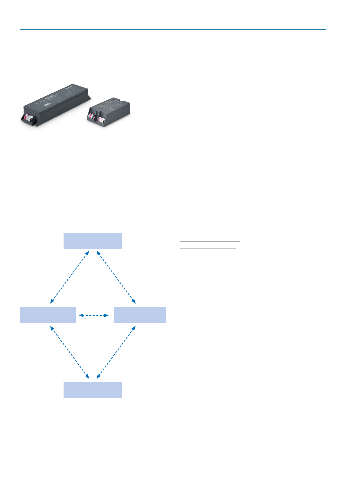
Xitanium LED Xtreme SR driver versions
The Xitanium LED Xtreme SR drivers described in this guide are
available in multiple power and current ratings which enable the most
popular light output levels for outdoor and industrial applications. It is
always highly recommended to check our latest Xitanium LED Xtreme
SR driver leaflet for the most up-to-date overview of our range. This
leaflet can be downloaded at www.philips.com/oem.
Detailed driver specifications can be found in the Xitanium
LED driver datasheets which can be downloaded at www.philips.com/
oem. Product specifications and datasheets can be accessed via the
Easy Design-in tool at www.easydesignintool.com.
Configurability Interface (tooling)
The Xitanium LED Xtreme SR drivers are configurable. A large
package of features and parameters in these drivers can be set via a
specific tool. This tool is the MultiOne Configurator. There are two
types of interfacing technology used to communicate with this tool:
•Wired: SR (DA+/DA-) interface (based on DALI 2 protocol)
•Wireless: SimpleSet
SimpleSet
Philips SimpleSet new wireless programming technology allows
luminaire manufacturers to quickly and easily program Xitanium
LED Xtreme SR drivers in any stage during of the manufacturing
process, without a connection to mains power, offering great
flexibility. As a result, orders can be met faster while reducing
cost and inventory.
For more information, please visit www.philips.com/multione or
contact your local Philips representative.
•
•
•
•
•
•
•
•
•
•
•
•
•
Design-in Guide - Philips Xitanium LED Xtreme SR driver
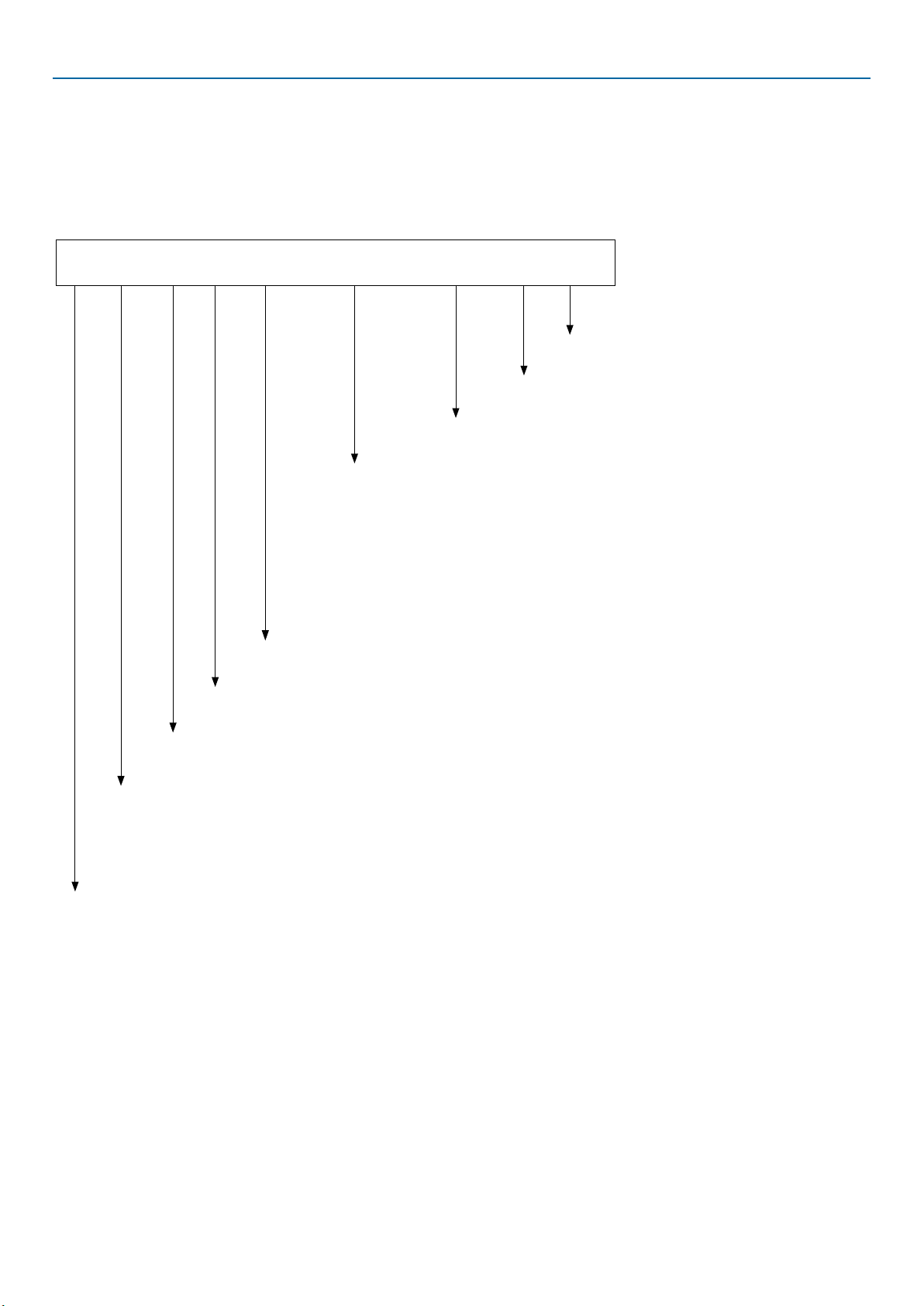
Xitanium LED Xtreme SR driver: general feature overview
Please refer to the applicable driver datasheet for an exact feature overview
•
DALI interface

Sensor Ready Interface (DA+/DA-)
Xitanium LED Xtreme SR drivers reduce complexity and cost of
luminaires used in (wireless) connected lighting systems. They
feature a digital SR interface to enable direct connection to any
suitable luminaire-based CMS (City Management System)
controller or sensor. Functionality integrated into the SR
driver eliminates the need for auxiliary luminaire components
such as power supplies and relay boxes used in many typical
outdoor lighting controllers (OLC) today. The result is a
simpler, less expensive luminaire that enables turning every luminaire
into a wireless node and a more reliable DC powered controller.
The simple two-wire SR (DA+/DA-) interface supports
these key functions:
• Switchable built-in SR bus power supply to provide power to the
connected control device (e.g. an RF module or an OLC)
• Two-way digital communication between the SR driver and
control device, based on DALI 2 protocol
- Standard DALI dimming, ON/OFF (excl. commissioning)
- Power and energy reporting utilizing the power monitoring
integrated in the driver
- Diagnostic information
These functions are described further in this document.
Warning: although communication via the SR (DA+/DA-) interface
is based on DALI 2 protocol, the interface itself is not a DALI
interface!
Compatibility with regular DALI 2 devices
SR Certified Products are designed to fully benefit from the SR driver
capability. DALI Edition 2 compliant devices can also be applied in
conjunction with SR drivers, yet with limited functionality.
Compatibility with outdoor CMS systems
In the outdoor segment, the preferred option is to apply the SR
driver in combination with the SR interface for both the CMS nodes
and potentially additional sensors. The Xitanium SR drivers can be
used in combination with a DALI Edition 2 compliant device.
However, a full system verification is advised to avoid high customer
dissatisfaction and significant costs to repair.
Auxiliary Power Supply
Next to the SR bus power supply, the Xitanium LED Xtreme
SR drivers are equipped with a permanently-enabled internal 24
VDC power supply which is short-circuit proof and intended to
power auxiliary luminaire devices that need more power than
the SR bus can deliver. This supply can deliver 3W
continuously and 10W peak with a duty cycle of 25% (t = 5.2
ms). This supply shares its common with the SR bus supply
common. In case of a short – circuit, the light will switch off.
Note: It is not allowed to connect the auxiliary power supply of
one driver in parallel to the auxiliary supply of another
driver. These supplies need to be kept separated from each other.
Design-in Guide - Philips Xitanium LED Xtreme SR driver 6

7
Adjustable Output Current (AOC)
Flexibility in luminaire design is ensured by the adjustable output
current (AOC). The adjustable output current enables operation of
various LED configurations from different LED manufacturers whilst
also ensuring the solution remains “future proof” for new LED
generations. The output current can configured with the Philips
MultiOne Software and the SimpleSet interface. More information
about AOC and how to set the output current can be found in the
section “Electrical design-in”. Information about configuring drivers
with SimpleSet can be found in the section “Configurability”.
LED Module Temperature Protection (MTP)
Adjustable limitation of thermal stress on the LED module is
made possible by the Module Temperature Protection (MTP)
feature combined with an NTC resistor integrated in the
LED module. More details about MTP and the NTC
resistor can be found in the Section “Thermal design-in”.
Driver Temperature Limit (DTL)
Adjustable limitation of thermal stress on the driver is
made possible by the DTL feature by means of an
NTC resistor integrated in the driver. Depending on luminaire
design, DTL can also be used as alternative for MTP. More details
about DTL can be found in the Section “Thermal design-in”.
Dimming interfaces
Interfacing with the Xitanium LED Xtreme SR drivers can be done
via the SR interface.
Amplitude Modulation (AM) dimming
Philips Xitanium LED Xtreme SR drivers dim the output to the
LEDs by means of continuous Amplitude Modulation (AM)
dimming of the DC output current. No Pulse Width Modulation
(PWM) is applied across any part of the entire output
current range. AM dimming guarantees the most smooth
and flicker-free operation over the entire dimming range.
Ripple and flicker
A small inherent ripple is superimposed on the DC output
current of Philips LED Xtreme SR drivers. This ripple
consists of a low-frequency LF component (double the
mains grid frequency) and a high-frequency HF component and
has such a low amplitude that optical interference (flicker)
with camera systems other than those for high-speed HD
recording is not be expected. The ripple value of both
components are specified in the driver datasheet.
Hot-wiring
Philips LED Xtreme SR drivers do not support hot-wiring. In
order to prevent damage to LED module and/or driver
no connection or disconnection should be made to the
driver output when mains voltage is present. Please ensure
that power is turned off before doing so.
DC mains operation
Xitanium LED Xtreme SR drivers support operation in a DC power
grid (e.g. central emergency system). The driver behavior once
switched to DC input voltage can be programmed via MultiOne
software. More details about DC input voltage suitability can be
found in the driver datasheet.
Design-in Guide - Philips Xitanium LED Xtreme SR driver

8
Constant Light Output (CLO)
Traditional light sources suffer from depreciation in light output
over time. This applies to LED light sources as well. The CLO
feature enables LED solutions to deliver a constant lumen output
throughout the life of the LED module. Based on the type of LEDs
used, heat sinking and driver output current, a correction of the
lumen depreciation can be entered into the driver. The driver then
counts the number of operating hours and will correct the output
current based on this input.
Since a CLO curve is not generic, the OEM needs to determine the
appropriate CLO curve. This can be used to differentiate on e.g.
lumen output or power consumption over lifetime.
The CLO feature can be programmed with the Philips MultiOne
configurator tool. More information can be found on
www.philips.com/multione.
OEM Write Protection (OWP)
OWP allows the OEM to protect their driver setting over
the lifetime of the driver by using a password. Drivers equipped with
OWP will show this in the feature list if read out by the tool
MultiOne. Specific features and also the OWP feature itself can
be enabled and protected with that password to prevent
unauthorized changes. The password management is under the
responsibility of the company which is setting it.
Driver diagnostics
Xitanium LED Xtreme SR drivers offer a Diagnostics feature. The
purpose of Diagnostics is to gather information and help diagnose
the history of the driver and connected LED module. The
Diagnostics feature consist mainly of counters which keep track of
specific variables like the number of startups of the driver, operating
hours, temperature of driver and LED modules, current and voltages
etc. When the driver is shutdown the diagnostics data is stored
automatically in non-volatile memory. Diagnostics can also be
accessed through the SR interface with a password provided to SR
Certified partners.
More information on the diagnostics see instruction manual of
MultiOne Engineering at: www.philips.com/multione
Energy Metering
The SR driver has built-in energy metering capability and
can report metered energy and actual power consumption. The
metering is compliant per EN50470-1 and EN50470-3.
Accuracy of the power measurement is the higher of
following two values across the entire driver operating window:
0.5W or +/-1% of measured input power. The energy metering
feature stores consumption parameters in the non-volatile
memory bank specified in the DALI 2 standard and the SR
Certified specification.
Design-in Guide - Philips Xitanium LED Xtreme SR driver

9
Driver naming
Xitanium LED Xtreme SR drivers are part of a specific naming
system. See the example below.
Protection suffix:
sXt = Xtreme technology; high robustness and lifetime
Housing
S###, C### (S=Stretched, C=Compact, ### = length in mm)
Rated AC input voltage
230VAC (= 220-240VAC)
HW Features
S = SimpleSet
N = NTC interface
L = LineSwitch
1 = 1-10V interface
D = DALI interface
A = AmpDim
E = DC Emergency
M = Energy Metering
P = Auxiliary Power supply
Output curr
ent:
Programmable min-max output current range (AOC) in A
Output power:
Rated Output Power (max)
LED driver family:
FP = FULL Prog
LP = LITE Prog
SR= Sensor Ready
BP = Basic Prog
Type of LED driver:
Xitanium (Xi)
Xi SR 150W 0.2-0.75A SNEMP 230V S240 sXt
Number of output channels:
Either one (no indication) or two (2)
Design-in Guide - Philips Xitanium LED Xtreme SR driver

10
Mechanical Design-in
Form factors
Xitanium LED Xtreme SR drivers are available in different
housing dimensions. The specific dimensions can be found in
the driver datasheet. 3D CAD files are available to verify fit and
can be found at www.philips.com/technology.
It is recommended to build in drivers such that the driver housing
and the driver input and output connectors are not affected by
potential water ingress in the luminaire (e.g. due to luminaire sealing
malfunction or condensation).
It is highly recommended to mount the driver by using all available
mounting feet in order to achieve maximum mechanical robustness
against shocks and vibration. The recommended mounting torque is
1.5Nm for drivers with plastic mounting feet. This value should not
be exceeded in order to prevent deformation of the mounting feet.
Note: The use of rivets is not recommended since mounting torque
cannot be controlled. Damage to the mounting feet and loose
mounting may result.
Mounting screw dimensions should be based on the specified fixing
hole diameter in the driver datasheet. Oversized and undersized
screws should not be used in order to prevent damage to the
mounting feet or loose mounting.
Allow for sufficient free space around the driver SimpleSet
antenna if the driver is to be configured after mounting in the
luminaire. The minimum recommended space is depending on the
type of SimpleSet configuration tool. Using the tool as shown here
(LCN9620), the minimum distance is 19 mm (+/-1mm).
Depending on the application and the use in development, factory or
field, another configuration tool can be selected. Please check the
website www.philips.com/multione to find the correct type.
Every published interface tool is officially approved for use with the
MultiOne software. The tool type number can be found by checking
the LCN label on the tool itself.
Note: the use of an unapproved tool may result in impaired driver-
tool communication and configuration malfunctioning.
LCN9620 SimpleSet interface tool
Design-in Guide - Philips Xitanium LED Xtreme SR driver

11
Thermal Design-In
Introduction
This section describes the following aspects of the thermal design-in
of the Xitanium LED Xtreme SR drivers:
1. The LED driver and the relationship between the Tc point
temperature and lifetime of the LED driver.
2. The LED driver and its non-adjustable response to driver
overheating (ThermalGuard).
3. The LED driver and configurable Driver Temperature Limit
(DTL) to maximize driver and possibly LED module lifetime in
the application.
4. Module Temperature Protection (MTP) function to safeguard
the specified LED module lumen maintenance and lifetime.
To facilitate design-in of LED drivers, the critical thermal
management points of the LED driver are set out in this section. In
Philips’ product design phase all possible precautions have been
taken to keep the component temperature as low as possible.
However, the design of the luminaire and the ability to guide the
heat out of the luminaire are of utmost importance. If these thermal
points are taken into account this will ensure the optimum
performance and lifetime of the system.
Driver case temperature point (tc point)
To achieve optimal lifetime and reliability, it is critical that the
temperature of the components in the driver remains within its
rating.
The driver case temperature (tc) is a reference for the
temperatures of the critical internal driver components. The
location of the tc point is identified on the product type plate and is
marked by a * or O symbol.
How to measure tc point temperature
Its temperature can be measured using a thermocouple that is
firmly glued to the driver housing. For a representative
measurement the temperature of the tc point must be stable before
any reliable data can be obtained (typically > 3 hours or when the
temperature difference is less than 1°C within one hour)
Note: Xitanium Xtreme SR drivers allow for a driver-
internal temperature readout through the MultiOne
Diagnostics feature. This readout is purely for diagnostic
purposes and does not represent the driver tc point
temperature. Therefore, this readout should not be used to
define thermal suitability of the driver in the application.
Design-in Guide - Philips Xitanium LED Xtreme SR driver

12
Relation between tc and ambient temperature
The tc increases, by approximation, linearly with the driver ambient
temperature (ta). The temperature offset between driver ta and tc
depends on the thermal design of the luminaire and the actual
delivered output power relative to the specified nominal
output power. A lower output power allows for a higher
driver ambient temperature as long as the maximum specified
driver tc is not exceeded. For the approved driver ambient
temperature range as well as specified tc point values please
check the specific driver datasheet.
Note:
The specified tc(max) and minimum ta temperature limit values are
not allowed to be exceeded in the application; otherwise driver
warranty will be void and driver failure rate will increase.
ThermalGuard
In a thermally well-designed lighting system the specified tc(max)
value will not be exceeded. However, under extreme hot
application conditions the driver may occasionally overheat. In
that case the driver will automatically start to reduce the
output current as an emergency measure in order to reduce
excess heat generation in the LED module and in the driver
itself. The result of the output current reduction will be a
mitigation of the excess decrease of driver lifetime as a result
of thermal overstress. Once the tc point temperature starts
dropping the driver will automatically increase the output current
up to the pre-set output current.
If the output current reduction is not sufficient to offset the tc point
temperature increase then the output current may either stabilize at
a lower value or –depending on driver type- even be reduced to
zero in extreme cases.
This thermal driver protection feature is called ThermalGuard and
its goal is to get the driver back in normal operating thermal
conditions in which the specified driver lifetime can be met. Each
driver type has its own specific overheating behavior and it can be
found as a ThermalGuard graph in the driver datasheet. The
ThermalGuard feature can neither be disabled nor reconfigured.
Note: the ThermalGuard feature is designed as a non-
configurable emergency measure to protect the driver. It is not
intended for structural activation to compensate for a poor
thermal design of a lighting system.
Design-in Guide - Philips Xitanium LED Xtreme SR driver

13
Shown on the left is an example graph of the ThermalGuard feature.
In this example, the output current is reduced from tc point
temperature = 86°C onwards down to 10% at 92°C. Between 92°C
and 96°C the output current will remain at 10%. If the output
current reduction is sufficient to decrease the tc point temperature
then the output current will be increased accordingly up to the pre-
set 100% level.
If the output current reduction is not sufficient to offset the tc point
temperature increase then the output current is eventually reduced
to zero at 96°C and the driver output will be switched off. Normal
operation will not resume until the tc point temperature has cooled
down to 92°C. A power cycle is not required to resume driver
operation. The 4°C hysteresis will prevent the luminaire from
blinking on and off as a measure to prevent nuisance.
Driver Temperature Limit (DTL)
Depending on commercial or application needs it may be required
to improve driver lifetime. This can be achieved by safeguarding
that the maximum driver case point temperature in the application
is not exceeding a predefined limit set below tc(max). The
configurable DTL feature enables this by offering an adjustable
tc point temperature threshold at which the output current is
reduced and switched off. DTL configuration can be done by
MultiOne software.
Shown on the left are a DTL and driver lifetime example graph. The
green line represents the output current as function of the tc point
temperature with DTL activated through a custom profile based on
the requirement that the driver lifetime be at least 75khrs. The red
line represent (non-configurable) ThermalGuard behavior. In
this example, the output current is reduced from tc point
temperature of 80°C onwards and the tc point will not exceed 86°C
whereas it would have been allowed to reach up to 96°C without
DTL enabled as defined by the ThermalGuard feature.
The DTL feature can also be applied as a substitute for Module
Temperature Protection (MTP) in order to protect the LED module
against overheating and to maintain a certain lumen maintenance.
The advantage of using DTL for this purpose is that the additional
NTC on the LED module plus required wiring can be omitted.
However, DTL can only be used as such if the thermal relation
between the driver tc point and LED module temperature is well-
defined. Therefore a meticulous thermal investigation of the driver -
LED module driver application is required to prevent DTL from
being activated at a too low or too high LED module temperature!
Warning: the DTL tc point threshold temperature at which the
output current should be reduced must not be set too
low. Otherwise, undesired light output reduction may result
during normal operating conditions. A meticulous thermal
investigation of the driver application is required to
ensure that the configured DTL threshold occurs neither at
too low nor at too high driver operating temperature conditions.
100
80
60
40
20
0
65 75 86 92 96
Tcase (°C)
lout (%)
100
75
50
0
-40 -20 0 20 40 60 80 86 100
Tcase (°C)
Lifetime (khr)
ThermalGuard
Design-in Guide - Philips Xitanium LED Xtreme SR driver

14
LED Module Temperature Protection (MTP)
This feature helps to protect the LED module when operated during
abnormal thermal application conditions. The thermal design of a
LED module should be designed in such a way that the temperature
of the LED module tc(life) ot tc(max) is not exceeded under normal
application conditions. The utilization of an NTC (Negative
Temperature Coefficient resistor) serves the purpose to help
achieve the useful lifetime of the LED module if external thermal
influences result in the temperature for lifetime tc(life) being
exceeded. If this occurs then the light output will be reduced to
keep the temperature of the LED module below a predefined critical
temperature.
Xitanium Xtreme SR drivers are by default configured for the
following three standard NTC types:
1. 10 kilo Ohm NTC - Murata, p/n NCP18XH103J03R or
NCU18XH103J60R
2. 15 kilo Ohm NTC - Vishay, p/n NTCS0805E3153GMT
(previous p/n: 2381 615 54153)
3. 15 kilo Ohm NTC - Murata, p/n NCP15XW153E03RC
(+ separate 390 ohms resistor in series with the NTC)
Other NTC types are supported as long as they fall within a 5,000 ...
25,000 Ohm resistance range. The applicable values for R(25°C) and
β however need to be specified separately during MTP configuration
in MultiOne for proper MTP behavior.
MTP behavior setting
It is possible to set the temperature at which the MTP feature is
activated, defined by “MTP warn” and the slope, defined by “MTP
max”. Using the MultiOne Configurator software these settings can
be changed.
•Warning: follow the instrictions below for reliable MTP
behavior and to prevent damage to the driver NTC interface.
•Do not combine the NTC ground connection with the LED -
connection. These two connections must be kept separate.
•The length of each wire between the NTC driver interface and
the NTC on the LED module is not allowed to exceed 60cm.
Donot use shielded wiring.
•It is neither allowed to connect multiple MTP inputs
from multiple drivers in parallel nor to have
multiple MTP interfaces share a common connection.
Always keep multiple MTP interfaces fully separated from
each other.
Design-in Guide - Philips Xitanium LED Xtreme SR driver

15
Electrical Design-In
Xitanium driver operating window
LED technology is rapidly evolving. The use of more efficient LEDs
in a next generation means the same light output can be achieved
with lower currents. At the same time, LEDs can be driven at
different currents levels based on the application requirement.
Typically, LED drivers are available in discrete current levels, e. g.
350 mA, 700 or 1050 mA. It is often necessary to replace a driver
when more efficient LEDs or different LED modules become
available.
One of the key features of the Xitanium LED Xtreme SR drivers is
the adjustable output current (AOC) feature, offering flexibility
and future-proof luminaire design. The Xitanium drivers can
operate in a certain “operating window”. This window is
defined by the maximum and minimum voltage and current
that the driver can deliver. An example of an operating
window is shown on the left. The area indicates the possible
current/voltage combinations. The current selected will depend
on the type and manufacturer of the LEDs or the
specific LED configuration of the PCB design. The voltage is
the sum of the LEDs used (total Vf string) and dependent
on LED drive current and temperature. The operating
window of every driver can be found in the driver datasheet.
The output current of these drivers can be set in two ways:
1. SimpleSet: output current can be set using the Philips MultiOne
software and SimpleSet interface.
2. SR interface: output current can be set using the DALI-2-USB
interface.
Warning: the forward voltage Vf of the connected LED
module must remain within the specified driver operating
window voltage boundaries under all application conditions!
Otherwise, reliable luminaire operation cannot be guaranteed.
250
Output voltage [V]
Output current [A]
200
150
100
50
0
00.1 0.2 0.3 0.4 0.5
5
1
3
4
2
Example Operating Window of a Xitanium driver
1. Required set point for the LED solution
2. Current can be set to needs within range (incl. dimming)
3. Driver adapts to required LED module voltage Vf, given it fits range
4. Driver minimum power limit
5. Driver maximum power limit
Design-in Guide - Philips Xitanium LED Xtreme SR driver

16
How to Select an appropriate driver
Depending on application requirements, several drivers may fit a
specific application. The following steps will help in selecting
the appropriate driver(s). For a complete overview of the
available drivers, please refer to www.philips.com/technology.
1. Determine the required driver current (Idrive) and voltage (Vf)
2. Calculate the required power (Pdrive) where Pdrive = Vf x Idrive
(W)
3. Select the datasheets from the website mentioned above based
on the driver having a higher power than required.
4. Does the required current fit the current range of the driver?
The current range of the driver can be seen in the name
itself. For example, for driver Xi SR 75W 0.2 – 0.7A SNEMP
S240 sXt, the minimum programmable driver current is 0.2 A
and maximum is 0.7 A.
5. Does the required voltage fit the voltage range of the driver?
The exact value can be found in in the datasheet.
6. Does the required power fit the power range of the driver? In
the naming of the driver, you can see the maximum possible
output power. For example, for driver Xi SR 150W SNEMP
S240 sXt, the maximum output power is 150W.
7. Choose the preferred dimming method. Please refer to the
section Driver naming to verify dimming options.
Programming the output current
The Xitanium LED Xtreme SR drivers offer an extensive range
of controls, enabling customizable luminaire design and performance.
It is possible to control light output levels, preset dimming
protocols and set system specifications in the factory and even in the
complete installations.
This can be done with the Philips MultiOne configurator. The
MultiOne configurator is an intuitive tool that unlocks the full
potential of all programmable drivers from Philips, ensuring that the
driver performance matches the needs of the lighting solution. It
offers unprecedented flexibility, before, during and after the product
installation.
Programming of new Xitanium LED Xtreme SR drivers can be done
either by using the SimpleSet or the SR interface.
For more information on MultiOne please refer to the section
Driver Configuration or visit: www.philips.com/multione. This site
contains detailed information on how to install the software and
how to program the driver.
Design-in Guide - Philips Xitanium LED Xtreme SR driver

17
Connectors
Philips Xitanium LED Xtreme SR drivers are equipped with
Wago or equivalent type push-in connectors. The mains, and
Equipotential connectors are -depending on driver type - Wago type
804 or 250 while the LED output and control connectors are
Wago type 250. All connectors accept stranded, solid core and
crimped wires. More info about connectivity (wiring diagram,
wire diameters, strip length) can be found in the driver datasheet.
Notes: although the driver connectors allow for quite small wire
cross section areas (down to 0.2mm2) it is recommended for optimal
connectivity to use mains and LED output wires having at least
0.5mm2 cross section area.
For currents between 1.0 and 1.5A (rms/DC) per connector, a
minimum cross section of 0.75mm2 is advised.
In some scenarios two wires need to be connected to one
connector terminal. In this case, the pairing has to be done outside
the driver, resulting in only one wire going into the
connector terminal. Two wires into one connector terminal are not
supported.
The reliability of twin-wire ferrules (or wire end stop), accepting the
wires intended to use, should be checked with the supplier of these
ferrules.
Mains operating conditions
Xitanium LED Xtreme SR drivers are designed for operation
and performance by power sources or grids providing a clean
and symmetric sinusoidal voltage wave form and do not
support operation on power sources including but not limited to
having e.g. a square-wave voltage form or a "modified sinewave".
Xitanium LED Xtreme SR drivers are able to withstand high and
low mains voltages for a limited period of time.
This includes under- and overvoltage due to malfunction such as a
loose neutral wire in the grid.
Low and high mains voltage
Xitanium LED Xtreme SR drivers are designed to be operated at
mains under- and overvoltage per IEC requirements for performance
and operational safety with respect to specified rated input voltage
range.
The applicable lower limit for driver performance is lowest rated
voltage - 8% while -10% applies for driver operational safety. For
drivers equipped with MainsGuard a lower limit applies for
operational safety.
The applicable upper limit for driver performance is highest rated
voltage +6 % while +10 % applies to driver operational safety.
The actual limit values can be found in the driver datasheet.
For optimal luminaire performance it is always recommended to
operate drivers within the specified voltage performance range.
Design-in Guide - Philips Xitanium LED Xtreme SR driver

18
Excessive low mains voltage (MainsGuard)
Previously, LED Xtreme drivers would turn off the output in case of
excessive low mains voltage. Depending on the exact driver type a
shutdown would occur between 150 ... 180VAC.
This shutdown functionality was intended to prevent overcurrent
conditions in the mains grid. Without shutdown the driver input
current would increase proportionally with decreasing mains
voltage since the driver is designed to maintain full light output of
the luminaire and thus output power. This would exacerbate
the undervoltage condition further. Consequently, mains cables
and relays may be overloaded and melting fuses and/or MCBs may
trip.
In order to prevent overcurrent conditions, a shutdown mechanism
had been implemented in the driver. However, the main
disadvantage of this shutdown is total loss of lighting.
Xitanium LED Xtreme SR drivers have a feature incorporated to
protect luminaire and mains grid against overcurrent conditions
without loss of lighting. This smart feature is called MainsGuard. Its
function is to proportionally decrease input current as function of
decreasing mains voltage and to keep doing so all the way down to a
much lower mains voltage before the driver output is ultimately shut
down. A small hysteresis of 5 ... 10V against on/off nuisance cycling is
implemented before the driver output becomes automatically active
again once the mains voltage starts to recover (no mains power
cycle required).
A general graphical representation of MainsGuard can be seen in the
illustration on the left. Exact values can be found in the MainsGuard
graph in the driver datasheet.
Main benefits of MainsGuard are:
•Light will remain on, even at excessive low mains voltage
• Luminaire and grid are protected against undervoltage and
overcurrent
• No current overloading of MCBs, fuses and relays
Note: the voltage levels at which output power is reduced and the
output is eventually shut down and re-activated are fixed and
cannot be modified.
100 120 140 160 180 200 220 240 260
0
20
40
60
80
100
120
140
160
Current (%)
0
30
20
10
40
50
60
70
80
90
100
Power (%)
Voltage
Input current and power vs. input voltage
PowerCurrent
Illustrative graph of the MainsGuard feature. Shown values are example values.
Please refer to the driver datasheet for exact values.
Design-in Guide - Philips Xitanium LED Xtreme SR driver
80

19
result
Excessive high mains voltage
An excessive high mains voltage will stress the driver and have an
adverse effect on the lifetime. Xitanium LED Xtreme SR drivers
will survive an input overvoltage of 264 ... 320VAC for a period of
max. 48 hours and 320 ... 350VAC for a period of max. 2 hours.
A loose neutral condition has to be avoided as this may reduce the
lifetime dramatically. Immediate driver failure may occur if the driver
is connected to 400VAC as a result of a connection error in a 3-
phase 230/400VAC grid.
Power grids
Xitanium Xtreme LED SR drivers are suitable for direct
connection to TN, TT and IT grids. Depending on driver type, a
luminaire-based fuse in the driver neutral connection may be
required in case both feeding phases are “hot”.
Note: certain restrictions apply for use in IT grids. Direct
connection of Xitanium LED Xtreme SR drivers is only permitted in
delta connection with a phase-to-phase voltage of 230VAC. In case
the drivers are connected in star connection in a 230V/400VAC IT
grid, the use of a separate 1:1 insulation transformer with sufficient
power rating is required to power the drivers. The secondary
output of the transformer must be connected to earth.
Power Factor (PF)
Xitanium Xtreme LED SR drivers have a high power factor
which is inherently capacitive. Its capacative nature cannot be
compensated for. The output power dependent PF graph can be
found in the driver datasheet.
DC emergency operation (DCemDim) and fusing
Depending on driver type, the driver may be certified acc.
IEC 61347-2-13 Part J for operation on a DC input voltage. As a
result, the driver enables application in emergency
luminaires in compliance with IEC 60598-2-22 excluding high-risk
task areas. These drivers support operation both a flat DC
input voltage as well as operation on rectified sinewave "joker"
input voltage.
On Xitanium LED Xtreme SR drivers, the DC Emergency Dim
feature named DCemDim is available. This feature allows a pre-
defined dim level of the driver output to which the driver will switch
over automatically once connected to a DC input voltage.
The mains input of DC-rated drivers is not polarity-sensitive for DC
input voltage and the driver is fully CISPR15 EMC-compliant when
operated on a DC grid. Specific DC input voltage values can
be found in the driver datasheet.
Depending on driver type, EL marking may apply. For those drivers
the corresponding Emergency Output Factor EOFx range can be
found in the driver datasheet.
Design-in Guide - Philips Xitanium LED Xtreme SR driver

20
Ipeak
T (@50%
of Ipeak)
Graphical representation of inrush current
Xitanium Xtreme LED SR drivers are equipped with an internal fuse
rated for AC & DC voltage operation. Thus, an external DC voltage
rated fuse is not required in case of DC operation.
More on setting parameters of DCemDim can be found in the
section for Controllability. Specific DC input requirements can
be found in the driver datasheet.
Note: The allowed DC input voltage range accepted by the
driver is stated in the driver datasheet. Values outside that range
will have an adverse effect on the driver performance and
reliability.
Inrush current
The term ‘Inrush current’ refers to the briefly occurring high
input current which flows into the driver during the moment of
connection to mains; see the illustration on the left. Typically, the
amplitude is much greater than the steady-state input current.
The cumulative inrush current of a given combined number of
drivers may cause a Miniature Circuit Breaker (MCB) to trip. In
such a case, either one or a combination of the following
measures need to be taken to prevent nuisance tripping:
•Replace existing MCB for a less sensitive type (e.g. exchange B
type for C type).
•Distribute the group of drivers over multiple MCB groups or
phases.
•Power up drivers sequentially instead of simultaneously.
Inrush parameters are driver-specific and can be found in
the driver datasheet.
Notes:
•The amplitude and pulse width time of the inrush current are
not in any way affected by the driver feature
Adjustable Startup Time (AST, see section Control
Features on p. 32 ).
•The use of an external inrush limiting device (e.g. EBN-OS or
Camtec ESB) or a zero-voltage switching relay (e.g Finder
77 series) may enable a larger amount of drivers to be
connected to a MCB. Philips has not tested the
effectiveness of such devices in the application. It is the
responsibility of both luminaire manufacturer and installer to
ensure compliance with national electrical codes when either
device is used in the application.
Design-in Guide - Philips Xitanium LED Xtreme SR driver
Table of contents
Other Philips DC Drive manuals
Popular DC Drive manuals by other brands

krispol
krispol STARCUS K06 Istallation Manual

Uniblitz
Uniblitz VincentAssociates VED24 instructions

Schimpf
Schimpf 00-10/30 STEP operating instructions

lumishore
lumishore SUPRA SY225 Installation and operating instructions

Danfoss
Danfoss VLT HVAC FC 100 Service manual

Pro-dig
Pro-dig T9K5 Operating Instruction, Maintenance Instruction

Magnetek
Magnetek HPV1000 Start guide

Danfoss
Danfoss VLT AutomationDrive FC 300 instruction manual

Franklin Electric
Franklin Electric SUBDRIVE UTILITY owner's manual

Binks
Binks 31-396 manual

Lenze
Lenze L-force ERBPR Series Mounting instructions

BONFIGLIOLI
BONFIGLIOLI TQ Series Installation use and service manual