5
Antriebe Typ 63 - 200L Schmalenberger GmbH + Co
Version: 27217 / A D-72013 Tübingen - Germany
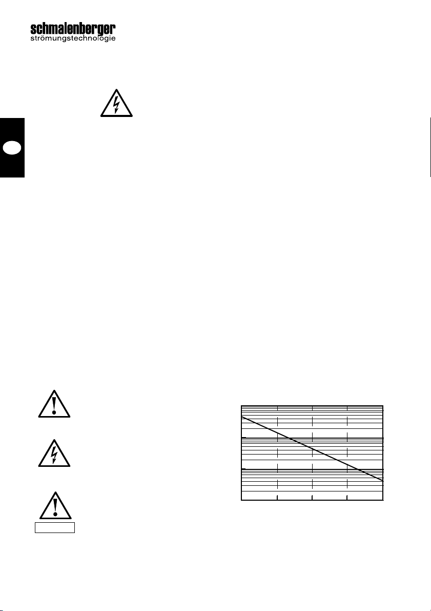
Hinweis
Der Isolationswiderstand ist stark temperaturab-
hängig! Ist der Isolationswiderstand zu gering,
mußder Motor getrocknet werden.
Dazu den Motor mit Warmluft erwärmen (max.
80 °C). Sie können den Trocknungsvorgang be-
enden, wenn der minimale Isolationswiderstand
(siehe Abb.1) überschritten wird.
Überprüfen Sie den Klemmenkasten ob:
•Innenraum trocken und sauber
•Anschluss- u. Befestigungsteile korrosions-
frei
•Deckeldichtung in Ordnung
•Kabelverschraubungen dicht sind.
Ist das nicht der Fall, dann: trocknen, reinigen
bzw. auswechseln der beschädigten Teile.
3 Montage des Antriebs
3.1 Vorbereitungen
Der Motor wird im Normalfall komplett mit dem
vorderen Lager („A“Seite) geliefert.
Reinigen Sie die Welle und Wellenenden gründ-
lich vom Korrosionsschutzmittel. Beachten Sie
dabei, dass das Lösungsmittel nicht in die Lager
gerät.
Reinigen Sie die Flanschflächen am Pumpenge-
häuse bzw. der Lagerlaterne.
Überprüfen Sie, dass Flanschanschluss von
Pumpe/Lagerlaterne und Antriebsmotor maßlich
übereinstimmen.
Überprüfen Sie, ob die Schutzart des Motors mit
den Anforderungen vor Ort bzw. der Anlage
übereinstimmen.
Demontieren Sie die wiederzuverwendenden
Teile vom alten Antrieb, z.B. Laufrad, Gleitring-
dichtung, Wellenschutzhülse usw..
Prüfen Sie alle demontierten Teile, die Sie wie-
derverwenden wollen auf Verschleißund sicht-
bare Schäden. Ersetzen Sie schadhafte Teile
durch neue.
3.2 Montage
Setzen Sie den Motor auf den Anschlussflansch
des Pumpengehäuses bzw. des Gegenflan-
sches der Lagerlaterne. Achten Sie dabei auf ei-
nen korrekten Sitz der Passung.
Zentrierrandtoleranz der Flansche nach
DIN 42948
- ISO j6 bei Ø≤ 230 mm
- ISO h6 bei Ø> 230 mm
Ziehen Sie die Befestigungsschrauben gleich-
mäßig über Kreuz fest an. Das Anzugsmoment
richtet sich nach dem Schraubendurchmesser
und sollte keinesfalls überschritten werden.
Anzugsmomente für Regelgewinde DIN 13
Schraubenklasse: 5.6 6.9 8.8
Schraube ØM8 10,8 21,6 25,5 NM
Schraube ØM10 21,6 42,0 50,0 NM
Schraube ØM12 38,2 73,5 87,2 NM
Schraube ØM16 93,2 178 211 NM
Die Angaben gelten für neue Schrauben, unge-
schmiert. Ausnutzung der Schrauben-Streck-
grenze von 90%.
Montieren Sie die vom alten Antrieb demontier-
ten Teile auf die Motorwelle. Beachten Sie dabei
die Montagehinweise in der Betriebsanleitung
zur Pumpe = Kapitel 4.2 und 4.3.
Kontrollieren Sie nach Abschluss der Montage
den freien Motorlauf von Hand, indem Sie durch
die Ansaugöffnung das Laufrad der Pumpe dre-
hen.
Sind diese Arbeiten ohne Beanstandung, kann
die Pumpe wieder in das Rohrleitungssystem
eingebaut werden.
4 Elektrischer Anschluss
4.1 Allgemein
Die folgenden Punkte sind unbedingt zu beach-
ten:
•Klemmenkasten möglichst so anordnen,
dass die Kabeleinführungen nach unten
weisen.
•Nur passende Kabelverschraubungen ver-
wenden und diese gut abdichten.
•Dichtflächen von Klemmenkasten u. Deckel
reinigen. Defekte Dichtungen austau-
schen. Dichtungen einseitig ankleben.
•Bei Motoren mit integriertem thermischen
Motorschutz, müssen die Kaltleiter immer
angeschlossen werden. Bei Nichtbeachten
erlischt die Garantie.
D