Product description
104273_en_01 PHOENIX CONTACT 9
1.1.1 Technical Data
Ethernet extender Type Order No. Pcs. / Pkt.
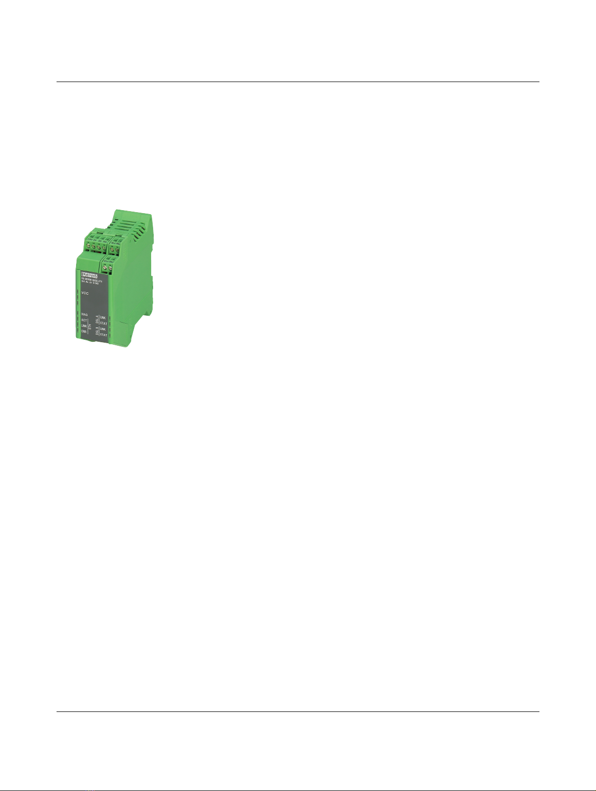
Industrial Ethernet extender, for point-to-point connections, line and ring
structures. Data rates of up to 30 Mbps on the in-house copper cables, inte-
grated diagnostic function, two configurable alarm outputs
PSI-MODEM-SHDSL/ETH 2313643 1
Accessories Type Order No. Pcs. / Pkt.
System power supply unit,
Primary-switched
Input voltage range
Nominal output voltage
Nominal output current
45 Hz ... 65 Hz
85 V AC ... 264 V AC
24 V DC ±1 %,
1.5 A
MINI-SYS-PS-100-240AC/24DC/1.5 2866983 1
DIN rail connector (2x required) ME 17.5 TBUS 1.5/ 5-ST-3.81 GN 2709561 1
Attachment plug with surge protection for two SHDSL telecommunica-
tions interfaces (ports). Connection: RJ45 (RJ12/RJ11) and plug-in screw ter-
minal block (COMBICON) Alternatively, can be snapped onto a DIN rail
DT-TELE-SHDSL 2801593 1
USB cable, USB connector type A to USB connector type mini-B, length: 3 m CABLE-USB/MINI-USB-3.0M 2986135 1
USB 2.0 cable, USB connector type A to USB connector type mini-B,
length: 1 m
PSI-CA-USB A/MINI B/1METER 2313575 1
19" Ethernet communication unit for networking systems and stations via
SHDSL technology. Data rates of up to 30 Mbps, distances of up to 20 km on
in-house copper cables via line, star, and ring structures. Diagnostics via
LEDs or software
TC ETH EXTENDER S19 2702077 1
Supply
Supply voltage 18 V DC ... 30 V DC
via plug-in COMBICON screw terminal block
24 V DC ±5 % (alternative or redundant, via DIN rail connector and system
power supply)
5 V DC (configuration only, via mini-USB type B)
Nominal current consumption < 180 mA at 24 V
LED indicator VCC (green LED)
Steady light: operation
Flashing at 1 Hz: supply via USB (for configuration)
Switching outputs 2 x VNom/ 150 mA (the digital outputs cannot be used for power supply via the
DIN rail connector), short-circuit-proof
The digital switching outputs can be connected to a load between 100 kilohm
and 0.2 kilohm.
SHDSL interface
Connection method 2 x 2-pos. COMBICON plug-in screw terminal block
Type SHDSL interface according to ITU-T G.991.2.bis
Serial transmission speed
4-wire operation
2-wire operation
64 kbps ... 30 Mbps (manual selection of the data rate)
384 kbps ... 11.39 Mbps (automatic detection of the data rate)
32 kbps ... 15.3 Mbps (manual selection of the data rate)
192 kbps ... 5.696 Mbps (automatic detection of data rate)
Transmission length Over 20 km possible at lower data rates and with good cable quality
Connection data (conductor cross section) 0.2 mm² ... 2.5 mm² (24 - 14 AWG)
Status and diagnostic indicators 2 x LINK, 2 x STAT (DSL data traffic port A and port B)
DIAG (yellow LED), diagnostic messages
ERR (red LED), errors