Phoenix Contact ED20KEXT User manual

User manual
UM EN TC EXTENDER...
Ethernet extender

2022-09-12
PHOENIX CONTACT GmbH & Co. KG • Flachsmarktstraße 8 • 32825 Blomberg • Germany
phoenixcontact.com
108102_en_01
Ethernet extender
Designation Firmware version Item No.
TC EXTENDER 2001 ETH-2S 5.xx 2702409
TC EXTENDER 4001 ETH-1S 5.xx 2702253
TC EXTENDER 6004 ETH-2S 5.xx 2702255
User manual
This user manual is valid for:
UM EN TC EXTENDER..., Revision 01

Table of contents
108102_en_01 PHOENIX CONTACT 3 / 110
Table of contents
1 For your safety ...........................................................................................................................5
1.1 Identification of warning notes ............................................................................... 5
1.2 Qualification of users ............................................................................................. 5
1.3 Field of application of the product.......................................................................... 6
1.4 Safety notes .......................................................................................................... 7
1.5 Installation in zone 2 .............................................................................................. 8
1.6 UL notes ..............................................................................................................10
1.7 Security in the network ........................................................................................ 11
2 Transport, storage, and unpacking ..........................................................................................12
2.1 Transport............................................................................................................. 12
2.2 Storage................................................................................................................ 12
2.3 Checking the delivery .......................................................................................... 13
3 Product description ..................................................................................................................14
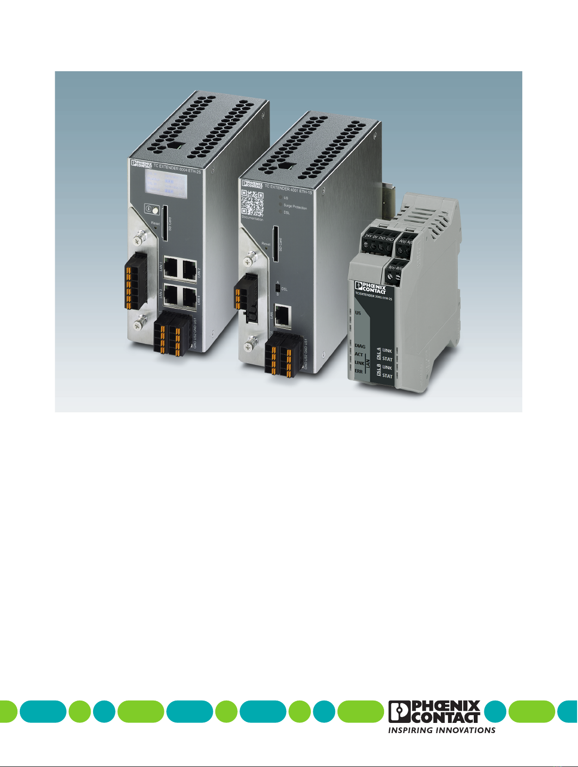
3.1 Unmanaged Ethernet extender............................................................................ 14
3.2 Managed Ethernet extender................................................................................ 15
3.3 Functions in firmware version 5.xx....................................................................... 15
3.4 Application examples .......................................................................................... 17
3.5 Open-source software ......................................................................................... 20
3.6 DSL technology................................................................................................... 21
3.7 Function elements TC EXTENDER 2001 ETH-2S............................................... 22
3.8 Function elements TC EXTENDER 4001 ETH-1S............................................... 25
3.9 Function elements TC EXTENDER 6004 ETH-2S............................................... 28
4 Installing ...................................................................................................................................30
4.1 Mounting and dismounting .................................................................................. 30
4.2 Connecting DSL .................................................................................................. 33
4.3 Connecting Unmanaged Ethernet extenders....................................................... 40
4.4 Connecting Managed Ethernet extenders ........................................................... 43
5 Surge protection ......................................................................................................................47
5.1 Managed Ethernet extenders with integrated surge protection............................ 48
6 Configuration ...........................................................................................................................50
6.1 Immediate commissioning and factory settings ...................................................50

TC EXTENDER...
4 / 110 PHOENIX CONTACT 108102_en_01
6.2 Mixed operation of Managed and Unmanaged Ethernet extenders..................... 52
6.3 System operation of Unmanaged Ethernet extenders ......................................... 52
6.4 System operation of Managed Ethernet extenders.............................................. 58
6.5 Diagnostics via IP ................................................................................................ 79
6.6 Display................................................................................................................. 84
7 Planning SHDSL networks .......................................................................................................87
7.1 Data rate and range............................................................................................. 87
7.2 Topologies........................................................................................................... 88
7.3 Slip ring communication ...................................................................................... 91
8 Device replacement, device defects, and repairs ....................................................................93
8.1 Device replacement............................................................................................. 93
8.2 Device defects and repairs.................................................................................. 93
9 Maintenance and disposal .......................................................................................................94
9.1 Maintenance........................................................................................................ 94
9.2 Disposal .............................................................................................................. 94
10 Technical data .........................................................................................................................95
10.1 Ordering data ...................................................................................................... 95
10.2 Accessories......................................................................................................... 95
10.3 Technical data..................................................................................................... 97
10.4 Compliance ....................................................................................................... 102
A Appendixes.............................................................................................................................104
A 1 List of figures ..................................................................................................... 104
A 2 List of tables ...................................................................................................... 107

For your safety
108102_en_01 PHOENIX CONTACT 5 / 110
1 For your safety
Read this user manual carefully and keep it for future reference.
1.1 Identification of warning notes
1.2 Qualification of users
The use of products described in this user manual is oriented exclusively to electrically
skilled persons or persons instructed by them.
– The users must be familiar with the relevant safety concepts of automation technology
as well as applicable standards and other regulations.
– The user must be familiar with the use of Ethernet network components.
When using Ethernet network components, there is a danger of data conflicts due to fault
conditions and a hazard to the data and network integrity due to unauthorized data access.
If in doubt, consult an Ethernet network specialist to assess the use of the devices and the
set configuration.
This symbol indicates hazards that could lead to personal injury.
There are three signal words indicating the severity of a potential injury.
DANGER
Indicates a hazard with a high risk level. If this hazardous situation is not avoided,
it will result in death or serious injury.
WARNING
Indicates a hazard with a medium risk level. If this hazardous situation is not
avoided, it could result in death or serious injury.
CAUTION
Indicates a hazard with a low risk level. If this hazardous situation is not avoided,
it could result in minor or moderate injury.
This symbol together with the NOTE signal word warns the reader of actions that
might cause property damage or a malfunction.
Here you will find additional information or detailed sources of information.

TC EXTENDER...
6 / 110 PHOENIX CONTACT 108102_en_01
1.3 Field of application of the product
1.3.1 Intended use
The TC EXTENDER... makes broadband Ethernet applications on existing cables possible.
You can use the Ethernet extenders for in-house 2 and 4 wire cables, but not in the public
telephone network. You can establish point-to-point, line, or ring structures with ranges of
up to 20 km.
You can use the Ethernet extender in a network with predecessor-generation devices (PSI-
MODEM-SHDSL/ETH from firmware version 4.xx, Item No. 2313643). This allows central
diagnostics to be performed for all users and lines via IP.
1.3.2 Product changes
Modifications to the device hardware or firmware are not permitted.
Incorrect operation or modifications to the device can endanger your safety or damage the
device. Do not repair the device yourself. If the device is defective, please contact
Phoenix Contact.
Updating the firmware is permitted. You will find the respective latest firmware version on
the product page at phoenixcontact.net/products.

For your safety
108102_en_01 PHOENIX CONTACT 7 / 110
1.4 Safety notes
WARNING:
Observe the following safety notes when using the device.
• The category 3 product is designed for installation in zone2 potentially explosive areas.
It satisfies the requirements of the following standards:
– EN/IEC 60079-0, EN/IEC 60079-7
– You will find detailed information in the declarations of conformity, which are en-
closed and are also available on our website in the latest version.
• Installation, operation, and maintenance may only be carried out by qualified electri-
cians. Follow the installation instructions as described.
• When installing and operating the device, the applicable regulations and safety direc-
tives (including national safety directives), as well as general technical regulations,
must be observed. The safety-relevant data is listed in this document.
• Observe the specified conditions for use in potentially explosive areas.
• Also observe the requirements of EN 60079-14.
• Opening or modifying the product is prohibited. Do not repair the product yourself; re-
place it with an equivalent product instead. Repairs may only be carried out by the man-
ufacturer. The manufacturer is not liable for damage resulting from non-compliance.
• Do not subject the product to mechanical and/or thermal stress that exceeds the spec-
ified limits.
• The product must be stopped and immediately removed from the Ex area if it is dam-
aged, has been subjected to an impermissible load, stored incorrectly, or if it malfunc-
tions.
• The product is not designed for use in potentially dust-explosive atmospheres.
• The device is designed exclusively for operation with SELV/PELV from a Class ES1
“electrical energy source” in accordance with EN/IEC 62368-1 and VDE 0868-1. The
device may only be connected to devices that meet the requirements of class ES1 in
accordance with EN/IEC 62368-1.

TC EXTENDER...
8 / 110 PHOENIX CONTACT 108102_en_01
1.5 Installation in zone 2
1.5.1 TC EXTENDER 2001 ETH-2S
WARNING: Explosion hazard when used in potentially explosive areas!
Make sure that the following notes and instructions are observed and complied with.
• Use in potentially explosive areas is not permitted in China.
• The device should be installed so that at least IP54 degree of protection is achieved in
accordance with EN 60529. To this end, a suitable, approved housing that meets the re-
quirements of EN 60079-7 should be used.
• Only devices which are designed for operation in Ex zone 2 and are suitable for the con-
ditions at the installation location may be connected to the circuits in the Ex zone.
• In potentially explosive areas, terminals may only be snapped onto or off the DIN rail
connector and wires may only be connected or disconnected when the power is
switched off.
• The configuration interface may only be used if it has been ensured that there is no po-
tentially explosive atmosphere present.
• For safe operation, lockable plug connections must have a functional interlock (e. g.
locking clip, screw connection etc.). Insert the interlock. Repair any damaged connec-
tors immediately.
• Only operate the device in Ex zone 2 when all plugs are fully inserted.
• Only connect one cable per terminal point.
• Use the device in an environment that does not exceed pollution degree 2 in accor-
dance with EN/IEC 60664-1.
• Use transient protection so that short-term surge voltages do not exceed 119 V.

For your safety
108102_en_01 PHOENIX CONTACT 9 / 110
1.5.2 TC EXTENDER 4001 ETH-1S and
TC EXTENDER 6004 ETH-2S
WARNING: Explosion hazard when used in potentially explosive areas!
Make sure that the following notes and instructions are observed and complied with.
• Use in potentially explosive areas is not permitted in China.
• The device should be installed so that at least IP54 degree of protection is achieved in
accordance with EN 60529. To this end, a suitable, approved housing that meets the
requirements of EN 60079-7 should be used.
• Only devices which are designed for operation in Ex zone 2 and are suitable for the con-
ditions at the installation location may be connected to the circuits in the Ex zone.
• In potentially explosive areas, only snap the device onto or off the DIN rail or connect
and disconnect the cables when the power is disconnected.
• For safe operation, lockable plug connections must have a functional interlock (e. g.
locking clip, screw connection etc.). Insert the interlock. Repair any damaged connec-
tors immediately.
• Only connect one cable per terminal point.
• Replace the SD card only when the power is disconnected or when an explosive atmo-
sphere is not present.
• Between the DSL connection, UB, and FE, surge protective devices discharge interfer-
ence < 500 Vrms.
• Only operate the device in Ex zone2 when all plugs are fully inserted.
• Use the device in an environment that does not exceed pollution degree 2 in accor-
dance with EN/IEC 60664-1.
• Use transient protection so that short-term surge voltages do not exceed 119 V.
• The device must be installed upright in Zone 2.
• A distance of 40mm must be maintained from external sources of heat.
• Before measuring the insulation, disconnect the plugs for the DSL cables and power
supply. Otherwise, inaccurate measurements may occur. Reinsert the plugs once the
insulation measurement has been completed.

For your safety
108102_en_01 PHOENIX CONTACT 11 / 110
1.7 Security in the network
NOTE: Risk of unauthorized network access
Connecting devices to a network via Ethernet entails the risk of unauthorized access
to the network.
Observe the following safety notes!
• If possible, deactivate unused communication channels.
• Assign passwords so that third-parties cannot access the device and make unautho-
rized changes.
• Due to its communication interfaces, the device should not be used in safety-critical ap-
plications unless additional security appliances are used. Please take additional pro-
tective measures in accordance with the IT security requirements and the standards
applicable to your application (e.g., virtual networks (VPNs) for remote maintenance
access, firewalls, etc.) for protection against unauthorized network access.
• On first request, you shall release Phoenix Contact and the companies associated with
PHOENIX CONTACT GmbH & Co. KG, Flachsmarktstrasse 8, 32825 Blomberg, Ger-
many in accordance with §§15ff. AktG (German Stock Corporation Act), hereinafter
collectively referred to as “Phoenix Contact”, from all third-party claims made due to im-
proper use.
• For the protection of networks for remote maintenance via VPN, Phoenix Contact offers
the mGuard product series of security appliances, which you can find described in the
latest Phoenix Contact catalog (phoenixcontact.net/products).
• Additional measures for protection against unauthorized network access can be found
in the AH EN INDUSTRIAL SECURITY application note. The application note can be
downloaded from the item page at phoenixcontact.net/product/2702409.
1.7.1 Brief Ethernet network information
The Unmanaged extenders do not have their own IP address. They are transparent for the
network.
The Managed extenders have their own IP address.
– Delivery state: Alternating BootP/DHCP client
– State after reset using the 2-2-5 method (see page 60):
– IP address: 192.168.0.254
– Subnet mask: 255.255.255.0
• If you use SNMP, RSTP, or VLAN, you will need special knowledge of the secure oper-
ation of Ethernet networks.
• Ensure that you avoid data conflicts and that the data integrity is safeguarded.

TC EXTENDER...
12 / 110 PHOENIX CONTACT 108102_en_01
2 Transport, storage, and unpacking
2.1 Transport
The device is delivered in cardboard packaging.
• Only transport the device to the intended location in its original packaging.
• Please observe the notes on handling on the packaging.
• Observe the humidity specifications and the temperature range specified for transport
(see “Ambient conditions” on page 100).
• Protect the surfaces as necessary to prevent damage.
• When transporting the equipment or storing it temporarily, make sure that the surfaces
are protected from the elements and any external influences, and that they are kept dry
and clean.
2.2 Storage
The storage location must meet the following requirements:
– Dry
– Protected from unauthorized access
– Protected from harmful environmental influences such as UV light
• For storage, observe the humidity and air pressure specifications, and the temperature
range.
– See “Ambient conditions” on page 100.

Transport, storage, and unpacking
108102_en_01 PHOENIX CONTACT 13 / 110
2.3 Checking the delivery
The device is supplied in the packaging together with a packing slip and installation instruc-
tions.
• Read the complete packing slip carefully before unpacking the device.
• Retain the packing slip.
NOTE: Electrostatic discharge
Electrostatic discharge can damage or destroy components.
–When handling the device, observe the necessary safety precautions against elec-
trostatic discharge (ESD) in accordance with EN 61340-5-1 and IEC 61340-5-1.
Checking the delivery • Check the delivery for transport damage.
Damaged packaging is an indication that transit damage may have occurred. This could re-
sult in a malfunction.
• Immediately upon delivery, check the delivery note to ensure that the delivery is com-
plete.
• Submit claims for any transport damage immediately, and inform Phoenix Contact or
your supplier as well as the shipping company without delay.
• Enclose photos clearly documenting the damage to the packaging and/or delivery to-
gether with your claim.
• Keep the box and packaging material in case you need to return the product.
• We strongly recommend using the original packaging to return the product.
• If the original packaging is no longer available, observe the following points:
– Observe the humidity specifications and the temperature range specified for trans-
port (see “Ambient conditions” on page 100).
– Use dehumidifying agents if necessary.
– Use suitable ESD packaging to protect components that are sensitive to electro-
static discharge.
– Make sure that the packaging you select is large enough and sufficiently thick.
– Only use plastic bubble wrap sheets as wadding.
– Attach warnings to the transport packaging so that they are clearly visible.
– Please ensure that the delivery note is placed inside the package if the package is
to be shipped domestically. However, if the package is being shipped internation-
ally, the delivery note must be placed inside a delivery note pocket and attached to
the outside so that it is clearly visible.

TC EXTENDER...
14 / 110 PHOENIX CONTACT 108102_en_01
3 Product description
With Ethernet extenders, you can connect Ethernet networks over distances up to
20 kilometers via simple 2-wire cables. You can combine Managed and Unmanaged Ether-
net extenders in the same network. This combination and easy startup using Plug and Play
enable cost-effective networking and diagnostics of all devices and paths via IP.
Features
– Automatic topology and data rate detection saves time and money
– Redundancy by means of RSTP (Rapid Spanning Tree Protocol)
– VLAN (Virtual Local Area Network) for logically separated IP networks
– Flexible use
– Point-to-point with double the bandwidth in 4-wire operation
– Line and ring topology with up to 50 devices
– Protocol-transparent transmission of all standard protocols:
– EtherNet/IP™
– Modbus/TCP
– PROFINET
– PROFIsafe
– EtherCAT®
– KNX
– BACnet/IP
– and more
3.1 Unmanaged Ethernet extender
The Unmanaged Ethernet extender allows easy startup via Plug and Play. The system can
be extended during operation without causing any adverse impact. Unlike the Managed ex-
tender, the Unmanaged extender is transparent for the Ethernet network.
The device does not have its own IP address. It is not necessary to configure the network or
the IP addresses.
Table 3-1 Product variants
Designation Item No.,
link
Description Topologies
TC EXTENDER 2001 ETH-2S 2702409 Unmanaged Point-to-point, line, ring
TC EXTENDER 4001 ETH-1S 2702253
Managed
1-port Ethernet Switch,
1 DSL port, LEDs Point-to-point
TC EXTENDER 6004 ETH-2S 2702255 4-port Ethernet Switch,
2 DSL ports, display Point-to-point, line, ring

Product description
108102_en_01 PHOENIX CONTACT 15 / 110
3.2 Managed Ethernet extender
Remote diagnostics via IP
With the Managed Ethernet extenders, you can diagnose all devices and paths centrally via
IP. There are two options available for remote diagnostics:
– Web-based, via the web server on the device
– Via SNMP using separate software, e.g., an MIB browser (not supplied as standard)
SNMP
In the web-based management, activate the SNMP traps. You can send the following event
messages:
– Device start
– Ethernet connection status changed
– DSL connection status changed
– Surge protection status changed
– DSL ring error
– User access data (admin) changed
– SD card has been inserted or removed
High-quality surge protection
PLUGTRAB PT-IQ is the forward-looking surge protection system from Phoenix Contact.
Your advantage: multi-stage monitoring of protective devices. This means that failures can
be foreseen.
– Integrated, replaceable SHDSL surge protection
– Automatic notification when replacement threshold reached or in the event of overload
3.3 Functions in firmware version 5.xx
Virtually separate critical IP networks with VLAN
All Ethernet extenders in the TC EXTENDER... product family support VLAN (Virtual Local
Area Network).
VLAN enables you to separate physical networks into logical subnetworks. Communication
is then only possible within the corresponding VLAN. Critical IP networks are isolated in this
way and communication is more secure.
Configure the VLAN manually as you usually would or with the support of a software assis-
tant.
If a device fails, you can replace it by means of Plug and Play. However, to do this, the
newly inserted device must be in the delivery state. The newly inserted device then
automatically adopts the entire configuration of the device it replaces.

TC EXTENDER...
16 / 110 PHOENIX CONTACT 108102_en_01
Possible VLAN system operation:
– Managed extenders only, configuration via web-based management
– Mixed operation of Unmanaged and Managed extenders, configuration via web-based
management
– Unmanaged extenders only, configuration via PSI-CONF software
Following configuration with PSI-CONF, you can use the VLAN functions in the Ether-
net network. However, the Unmanaged extenders are not visible with an IP address.
High availability thanks to RSTP redundancy
The Managed extenders support RSTP (Rapid Spanning Tree Protocol).
RSTP enables you to set up redundant ring or point-to-point topologies. The protocol auto-
matically disables duplicate or failed paths, thereby increasing network availability.
If a device fails, you can replace it by means of Plug and Play. However, to do this, the
newly inserted device must be in the delivery state. The newly inserted device then
automatically adopts the entire configuration of the device it replaces.
RSTP telegrams can also be transmitted in a network that only consists of Unmanaged ex-
tenders. However, you must operate the devices in hub mode.
• If the network only consists of Unmanaged extenders: deactivate switch mode in the
PSI-CONF software (IP Address Learning = active).
In mixed operation with Managed extenders, switch mode is automatically deactivated as
soon as you activate RSTP. However, to do this, all devices in the extender network must
already be connected to each other.
Greater transparency during diagnostics
The Managed extenders support SNMP (Simple Network Management Protocol).
For mixed operation of Unmanaged and Managed extenders, you can also read the status
of the Unmanaged extenders via SNMP (see 6.5.5 “Diagnostics via SNMP”).
Even more system events can be detected with the help of this function extension. You can
send alarm messages and diagnose system events via SNMP. This makes the communi-
cation network more transparent. In the event of malfunctions or tampering attempts, you
can initiate countermeasures quickly.
In conjunction with an MIB browser, the states of all Unmanaged extenders are also dis-
played via the IP address of the Managed extender. However, the Unmanaged extenders
do not have their own IP address in the network.
Along with the firmware update, it may be necessary under certain circumstances to also
update the MIB file in the MIB browser.
You will find the FW5.xx update package with the file EXTENDER_Private.MIB on our
website at phoenixontact.net/product/2702255.

TC EXTENDER...
20 / 110 PHOENIX CONTACT 108102_en_01
3.5 Open-source software
The notes below only apply to Managed Ethernet extenders.
3.5.1 Notes on LGPL software libraries
All open-source software used in the product is subject to the respective license terms that
are not affected by the end user license agreement (EULA) for the product.
In particular, the license holder can change the respective open-source software in accor-
dance with the applicable license terms. If the license holder wishes to change an LGPL
software library contained in this product, reverse engineering is permitted for debugging
such modifications.
3.5.2 Notes for OpenSSL
This product includes software developed by the OpenSSL Project for use in the OpenSSL
Toolkit. (http://www.openssl.org/)
3.5.3 Requesting source code
The devices contain software components which are licensed by the rights holder as free
software or open-source software under the GNU General Public License.
You can request the source code of these software components in the form of a CD or DVD-
ROM for a processing fee of 50 euros within three years after delivery of the device.
Contact the After Sales Service of Phoenix Contact in writing about this at the address:
PHOENIX CONTACT GmbH & Co. KG
After Sales Service
Flachsmarktstrasse 8
32825 Blomberg
GERMANY
Subject:
Source Code TC EXTENDER...
Table of contents
Other Phoenix Contact Extender manuals
Popular Extender manuals by other brands

Enable-IT
Enable-IT 865W PRO quick start guide

Sercomm
Sercomm CAP1800-AX quick start guide

TradExpertisse
TradExpertisse PODRP27 user manual

surveillance 112
surveillance 112 ACA1574X user manual

TP-Link
TP-Link RE450 Quick installation guide

Alcatel-Lucent
Alcatel-Lucent Data Multiplexer Explore 1665 installation manual