AMBR-THL
30A
•
•
1. Install all system fuses.
4. Turn the headunit on with the volume set to minimum.
2. Set the amplifier’s input
sensitivity control and bass
equalization control to minimum
(full counterclockwise).
3. Set all amplifier signal routing switches according to your
system’s design.
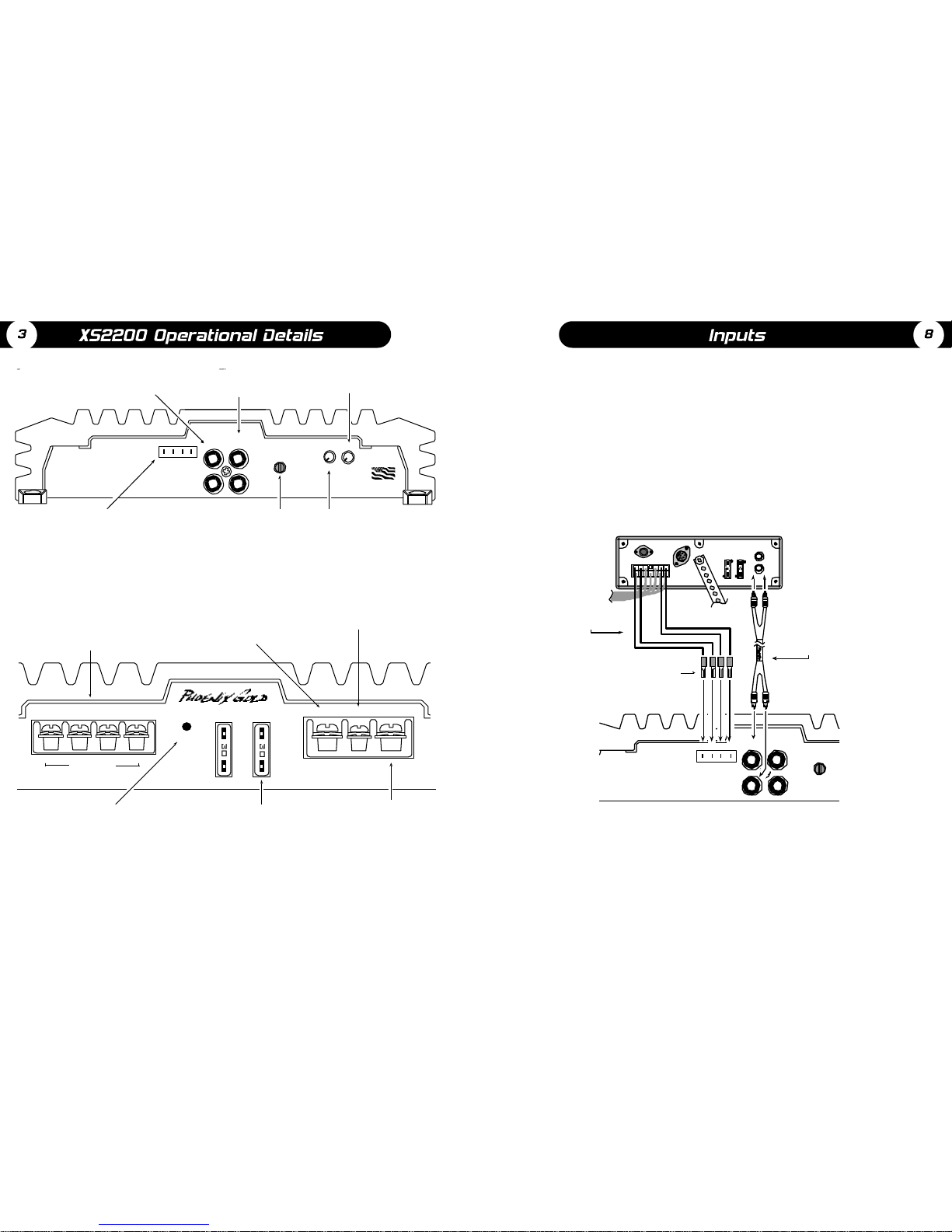
INPUT SENSITIVITY AND BASS ADJUSTMENT
5. Visually check the amplifier’s
condition. The green power LED
should be on.
7. Set the headunit’s tone controls, balance, and fader to the
center (flat) position. Turn off any loudness or other signal
processing features.
6. Check the condition of all other components to make sure
they are powered up and working.
8. Set the volume control of the headunit for maximum
undistorted output (on most headunits this will be
approximately 7/8 of maximum volume). Use a very clear
and dynamic recording.
13. With all levels set correctly, the system will reach overall
maximum undistorted output at the volume level set in
step 9.
11. Listen to various musical selections to check overall
system balance. Compare front to rear, midbass to
midrange, etc. If an amplifier is too loud compared to
the others, then its level must be lowered to blend
correctly with the weakest amp. The idea is to reference
all amplifiers to the capability of the weakest amp.
10. Reduce the headunit's volume to a comfortable level.
12. Adjust the Bass Equalization
Controls according to taste.
Note: Use these controls
sparingly. Every 3dB of boost
requires double the power at
45Hz. If your subwoofer
system requires 18dB of boost
to sound good, there may be
a problem. Look for out-of-
phase woofers, a leaking
subwoofer box, or incorrect
box size.
9. Use the amplifier’s sensitivity
control to reach maximum
undistorted speaker output.
Repeat this for all other
amplifiers. The idea is to find
maximum undistorted output
for each amplifier
independently.
•••
SENS BASS
3.1 0 18
•••
SENS BASS
3 .1 0 18
•••
SENS BASS
3 .1 0 18
•
Continuous Output Power at 1% THD (WRMS):
Into 4 ohms @ 12.5 (IASCA)/14.4 VDC 25/50 watts x 2
Into 2 ohms @ 14.4 VDC 100 watts x 2
Bridged into 4 ohms @ 14.4 VDC 200 watts x 1
Frequency Response ±1dB 20Hz to 20kHz
Signal to Noise Ratio (20Hz to 20kHz) >100dB
Input Sensitivity, Line Inputs 100 mVRMS to 3 VRMS
Input Sensitivity, Speaker Inputs 1.75 WRMS to 35 WRMS
Low Pass Crossover Frequency Fixed 90 Hz
High Pass Crossover Frequency Fixed 125 Hz
Crossover Slope 18dB per octave
Bass Boost @ 45Hz 0 to +18dB
DC Input Voltage Range 10 volts to 15.5 volts
Typical Current Draw at Idle 2 amps
Peak Current Draw @ Full Power 35 amps
Recommended Fuse Size 30 amp ATO style
Dimensions, Chassis 7.75”L x 9.25”W x 2.0”H
Dimensions, Overall 9.1”L x 9.25”W x 2.1”H
Due to continuous product development, features, specifications, and availability are subject to change without notice.
Features Cover
Introduction 1
Specifications 2
Operational Details 3
System Configurations 4-5
Powerflow™Systems 6
Installation-Mounting 7
Adjustments- Input Sensitivity and Bass Adjustment 8
Inputs 9
Troubleshooting 10
Limited Warranty 11