www.phoenixgold.com
Amplier Owner’s Manual
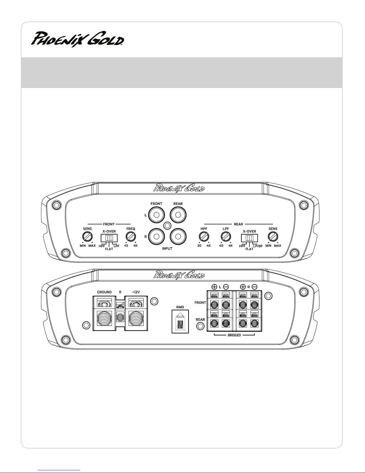
RMS Power Output 150w x 4 @ 4 ohms Stereo
250w x 4 @ 2 ohms Stereo
500w x 2 @ 4 ohms Bridged
Power/Ground Wire Size: 4 Gauge
Recommend Power Wire Fuse: 80a
Dimensions: 11.7” L x 7.1”W x 2.0” H
296mm L x 180mm W x 52mm H
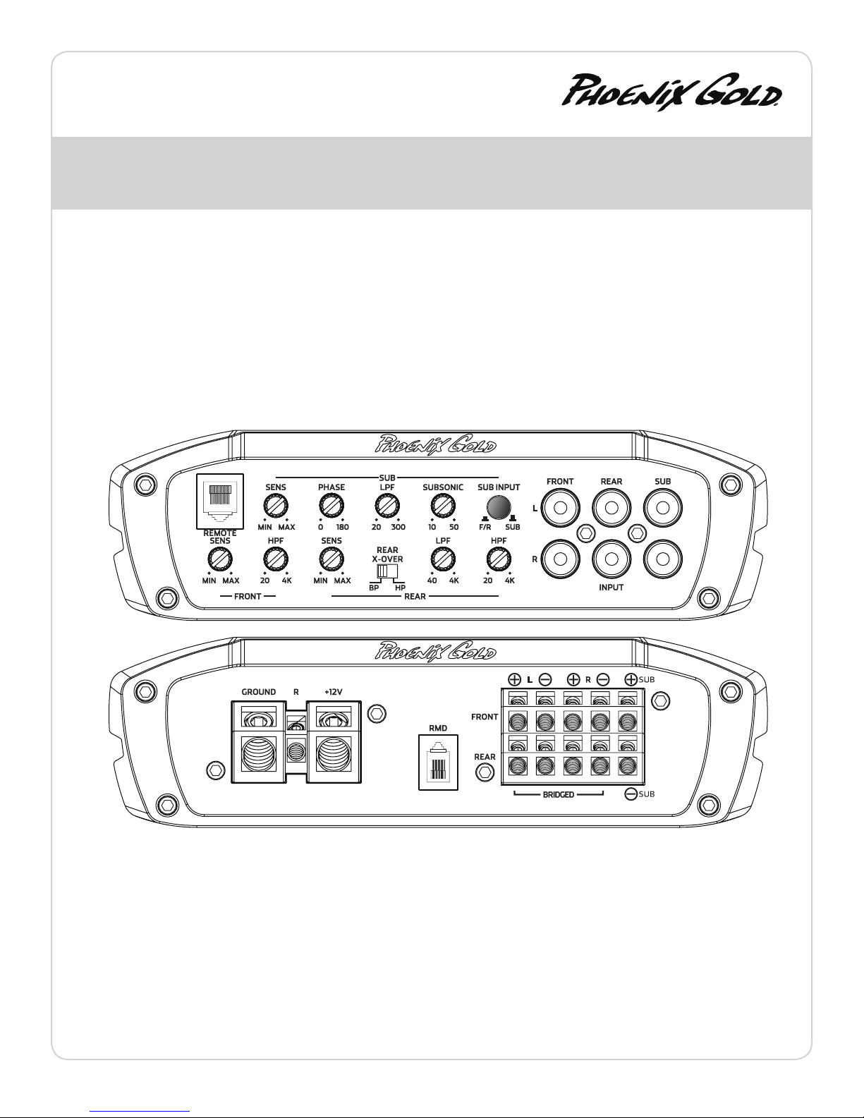
RMS Power Output 500w x 1 @ 4 ohms
800w x 1 @ 2 ohms
Recommend Power Wire Fuse: 100a
Power/Ground Wire Size: 4 Gauge
Dimensions: 14.4” L x 7.1”W x 2.0” H
366mm L x 180mm W x 52mm H
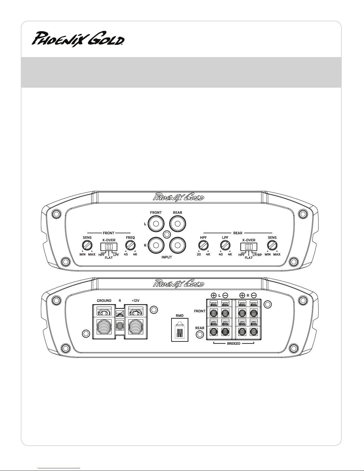
RMS Power Output 125w x 4 @ 4 ohms Stereo
200w x 4 @ 2 ohms Stereo
400w x 2 @ 4 ohms Bridged
Key Features
ADAPT POWER MANAGEMENT SYSTEM
Full power output from 11 to 15 volts: ADAPT delivers the same output
power regardless of the vehicle’s electrical system voltage. Instantaneous or
long term voltage drops have no eect on the amplier’s power output. This
means more dynamic and less distorted audio output.
Dual power modes provide maximum efficiency: ADAPT seamlessly
optimizes the power supply and Class D operating circuitry by adapting to
the end user’s listening habits. When the ADAPT circuit senses lower signal
levels, it will automatically optimize the amplier’s power supply and Class
D circuitry to a low power mode that maximizes eciency and minimizes
heat to almost zero. As a signal increase is detected the amplier instantly
shifts into a high power mode, where the power supply and Class D sections
are now optimized to deliver massive power and headroom for those
demanding listening sessions. The amplier is constantly monitoring and
adapting between these modes which results in higher overall eciency,
much lower operating temperatures and rock solid reliability.
BALANCED DIFFERENTIAL INPUTS
Provides maximum rejection of unwanted noise from upstream
components.
AUDIOPHILE NJM2068M OP-AMPS
Most mobile ampliers today use the standard NJM4558 op-amp which
has a bandwidth of 3MHz, slew rate of 1V/uSec and noise level of 1.4uV.
The NJM2068M is simply a better performer with a bandwidth of 19MHz,
slew rate of 6V/uSec and noise level of .44uV.
The result is quieter, faster and wider bandwidth performance that
ensures the original music material is reproduced as accurately as
possible.
ULTRA HIGH SPEED IR CLASS D CHIPSET
State of the art IR20957 chipset switches at more than 300kHz
for blistering audio performance. All four or ve chipsets are
sync’d together in unison to eliminate unwanted harmonics or
distortion.
POST FILTER FEEDBACK
Feedback is when part of the output signal is“fed back” into the
original signal to ensure stability and accurate sound. Class D
ampliers use output lters (see the 4 vertical coils below), but
most DO NOT INCLUDE these lters in the feedback loop. Ti2
ampliers INCLUDE or take feedback after its passed through
these lters. The result is more accurate sound that rivals some
of the best class A/B ampliers.
THERMAL ROLLBACK CIRCUIT
Under most conditions, Ti2 ampliers generate moderate
to low heat. However, if extreme conditions exist, as
temperatures rise the amplier will automatically adjust the
power output, so your music continues to play. These changes
are inaudible and vastly reduce the chance for any thermal
shutdown events.
LOW EMI CIRCUIT BOARD DESIGN
Most class D ampliers can emit EMI noise that can cause
problems with AM/FM reception or other devices in the
vehicle. Ti2 ampliers have undergone intense real world
engineering and testing to vastly reduce or eliminate these
issues. Careful PCB layout using four layers (most ampliers
feature just two) along with many key lters ensures a very
low possibility of any interference issues.
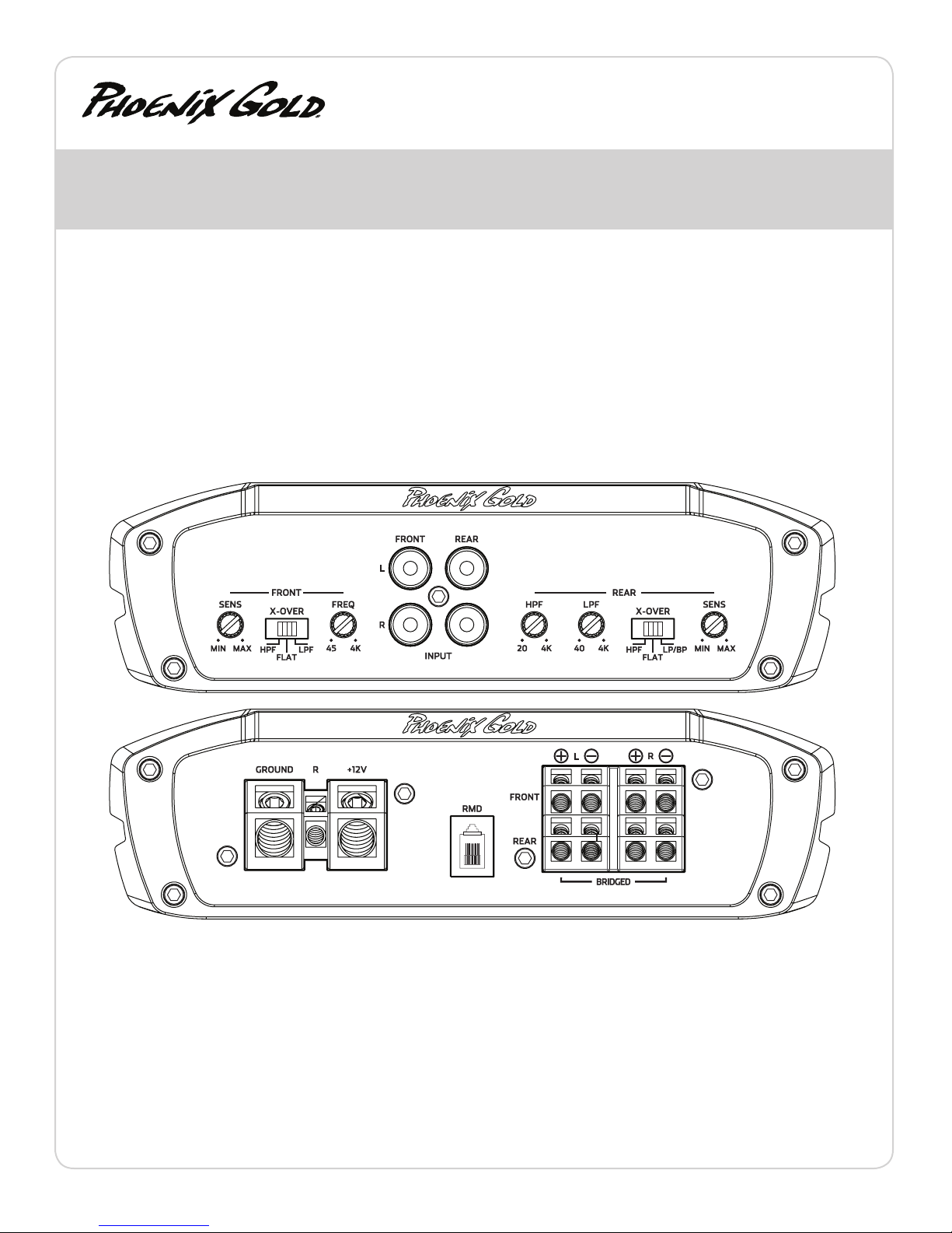
A
B
C
D
E
F
A
G
B
C
D
E F
G