5SUMMIT
AUX – Auxiliary – an auxiliary is anything that is supplementary
or additional to the main mix.
AFL – After Fader Listen – exactly as the name suggests, this is
a monitor signal that is taken after the signal has passed through
the fader/level control.
Balanced Connections – balanced connections offer three
conductors, carrying a ground, an in-phase signal, and an out-
of-phase signal. Once the two signals are sent from one device
to another, the out-of-phase signal has its phase inverted and
the two signals are combined. Any interference picked up along
the way is removed through to phase cancellation. This allows
cables to be run over long distances without collecting excessive
noise on the way.
Compressor – a Compressor reduces signals over a user-dened
threshold by a user-dened amount/ratio.
Dynamic Processor – is any kind of processor that dynamically
– or in real time – adjusts signal properties.
EQ – Equalizer – is a device or process that allows users to boost
or attenuate audio signals at specic frequencies.
Expander – an expander is a type of dynamic processor that
helps to make background noise (such as humming) inaudible
by reducing low-amplitude signals.
GUI – Graphical User Interface – this is the software that is featured
on the SUMMIT’s LCD display. Throughout this manual, this will
be referred to as the GUI.
HPF – High Pass Filter – a high pass lter will cut or signicantly
reduce all audio signals below a particular user-dened frequency,
allowing – as the name suggests – high frequency sounds to
pass through.
High Shelf Filter – the high shelf lter will reduce or increase all
audio signals below a particular frequency. The level at which the
signal is boosted/attenuated is determined by the user.
Layers – when we refer to layers, we refer to the function of the
faders on the hardware section of this mixer. Imagine your mixer
had 32 faders in total, the 16 you see and another 16 sitting
right on top of them (on a different layer). This is basically the
case. However, instead of two or three actual physical layers of
faders, users are able to change the functionality of the 16 faders
available.
Limiter – work just as compressors do; however with an input to
output signal ratio permanently set to innity-to-1.
LPF – Low Pass Filter – a low pass lter will cut all audio signals
above a particular user-dened frequency, allowing low frequency
sounds to pass through. This is signicantly useful when using
subwoofer speakers on particular outputs.
Low Shelf Filter – the low shelf reduces or increases the level of
audio signals below a particular frequency selected by the user.
The level at which the signal is altered is also set by the user.
Noise Gate – a noise gate is a dynamic process that turns off or
signicantly attenuates the audio signal passing through it when
the signal level falls below a user adjustable threshold.
PFL – Pre-Fader Listen – this is a form of signal monitoring where
the signal is taken prior to the level control/fader.
TRS – Tip-Ring-Sleeve – this is the name given to the type of audio
jack/plug that can accept signals through its tip, ring and sleeve.
Unbalanced Connections – unlike balanced connections,
unbalanced connections only have 2 conductors: one for the signal
and one for the grounding. This, unfortunately, makes them more
susceptible to noise and interference.
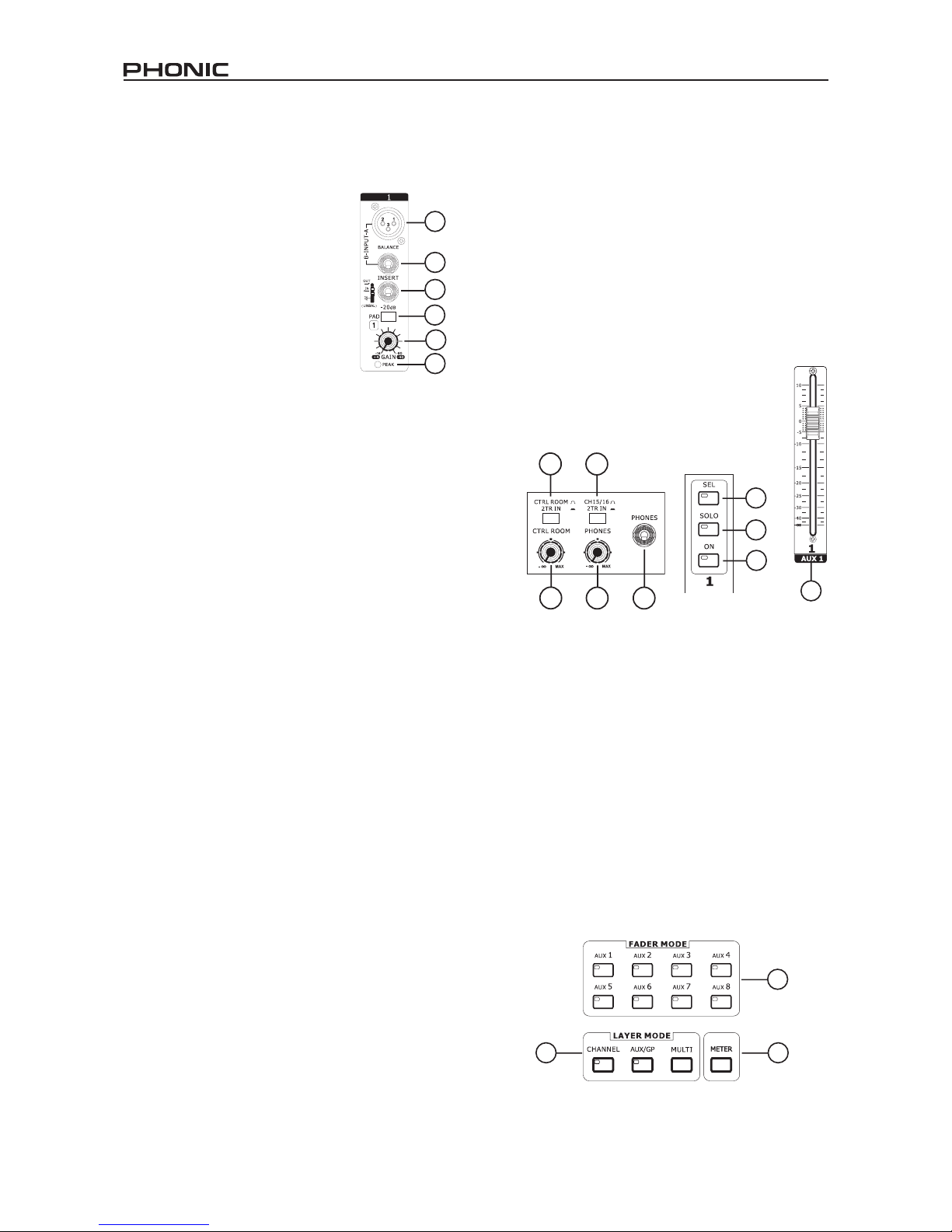
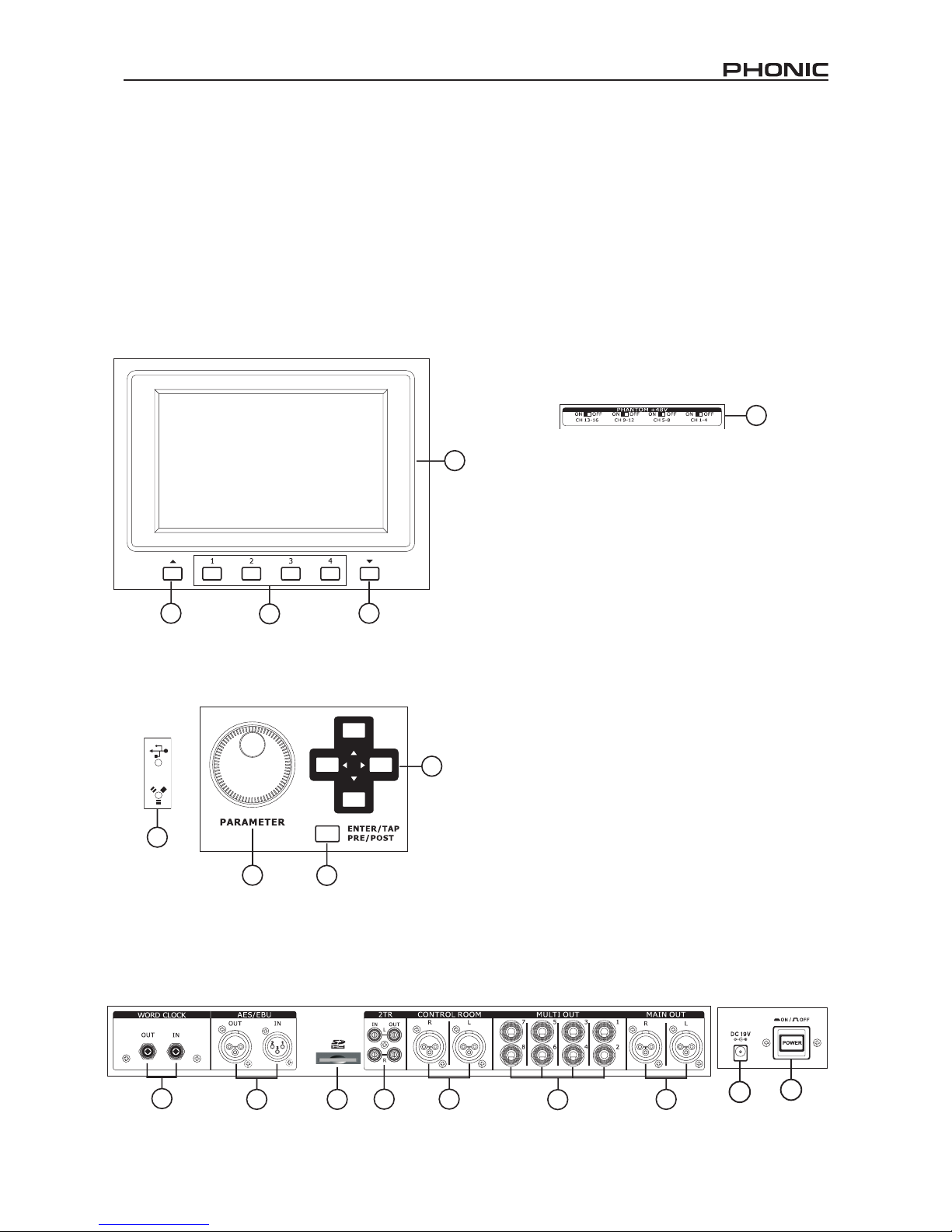
PART TWO: CONTROLS AND CONNECTIONS
Basic Setup
1. Make sure the SUMMIT’s power is off. To fully ensure this,
disconnect the power supply from the unit.
2. Connect your various input and output devices to the
SUMMIT. This may include microphones, guitars,
keyboards, synthesizers, and so forth.
3. Be sure to turn all your equipment on in the following order:
input devices/audio sources, multitrack recorders, SUMMIT
digital mixer, followed by amplifiers, monitors and active
speakers. This will help avoid loud pops, clicks, thumps and
such from damaging your equipment.
4. Connect the power supply, using the cable retaining clip to
hold it in place, and push the power button.
5. The SUMMIT’s routing is all accomplished through the
control software, therefore it’s necessary to enter the VIEW
menu to adjust input and output levels.
6. If using a digital device through the AES/EBU connectors,
enter the “Setup” menu and define the clock source
(whether internal, digital or through the word clock inputs).
If Digital or Word Clock is selected, the sampling rate will be
determined by the external source. Digital equipment can
be activated by pushing the DIGI IN and DIGI OUT buttons
in the main stereo mix’s setup page in the VIEW menu.
7. Users can check instrument input levels in the VIEW or
FADER menus, as both of these offers a level meter for
each of the individual input channels. Adjust the virtual
faders (or the physical faders, on the SUMMIT) to set levels
correct. Turn channels on and off as required.